


 Loading...
JVC GR-FXM404EX, GR-FXM404EY, GR-FXM404EZ, GR-FXM40EK, GR-FXM40EX Service Manual
...SERVICE MANUAL
COMPACT VHS CAMCORDER
GR-FXM40EK,GR-FXM40EX,GR-FXM40EY, GR-FXM40EZ,GR-FXM404EX,GR-FXM404EY, GR-FXM404EZ,GR-SXM30EF,GR-SXM50EX, GR-SXM50EY,GR-SXM50EZ
VHS
625 PAL
GR-FXM40EK/EX/EY/EZ [M4A622], GR-FXM404EX/EY/EZ [M4A623]
GR-SXM30EF [M4C622], GR-SXM50EX/EY/EZ [M4C723]
For disassembling and assembling of MECHANISM ASSEMBLY, refer to the SERVICE MANUAL No.86700 (MECHANISM ASSEMBLY).
TABLE OF CONTENTS
1 PRECAUTION. . . . . . . . . . . . . . . . . . . . . . . . . . . . . . . . . . . . . . . . . . . . . . . . . . . . . . . . . . . . . . . . . . . . . . . . . 1-3 2 SPECIFIC SERVICE INSTRUCTIONS . . . . . . . . . . . . . . . . . . . . . . . . . . . . . . . . . . . . . . . . . . . . . . . . . . . . . . 1-5 3 DISASSEMBLY . . . . . . . . . . . . . . . . . . . . . . . . . . . . . . . . . . . . . . . . . . . . . . . . . . . . . . . . . . . . . . . . . . . . . . . 1-6 4 ADJUSTMENT . . . . . . . . . . . . . . . . . . . . . . . . . . . . . . . . . . . . . . . . . . . . . . . . . . . . . . . . . . . . . . . . . . . . . . . 1-15 5 TROUBLESHOOTING . . . . . . . . . . . . . . . . . . . . . . . . . . . . . . . . . . . . . . . . . . . . . . . . . . . . . . . . . . . . . . . . . 1-21
COPYRIGHT © 2004 VICTOR COMPANY OF JAPAN, LIMITED
No.YF006
2004/1

SPECIFICATION
1-2 (No.YF006)
SECTION 1 PRECAUTION
1.1SAFTY PRECAUTIONS
Prior to shipment from the factory, JVC products are strictly inspected to conform with the recognized product safety and electrical codes of the countries in which they are to be sold.However,in order to maintain such compliance, it is equally important to implement the following precautions when a set is being serviced.
1.1.1 Precautions during Servicing
(1)Locations requiring special caution are denoted by labels and inscriptions on the cabinet, chassis and certain parts of the product.When performing service, be sure to read and comply with these and other cautionary notices appearing in the operation and service manuals.
(2)Parts identified by the  symbol and shaded (
  ) parts are critical for safety.
Replace only with specified part numbers.
NOTE :
Parts in this category also include those specified to comply with X-ray emission standards for products using cathode ray tubes and those specified for compliance with various regulations regarding spurious radiation emission.
(3)Fuse replacement caution notice.
Caution for continued protection against fire hazard. Replace only with same type and rated fuse(s) as specified.
(4)Use specified internal wiring. Note especially:
•Wires covered with PVC tubing
•Double insulated wires
•High voltage leads
(5)Use specified insulating materials for hazardous live parts. Note especially:
•Insulation Tape
•PVC tubing
•Spacers
•Insulation sheets for transistors
•Barrier
(6)When replacing AC primary side components (transformers, power cords, noise blocking capacitors, etc.) wrap ends of wires securely about the terminals before soldering.
Fig.1-1-1
(7)Observe that wires do not contact heat producing parts (heatsinks, oxide metal film resistors, fusible resistors, etc.)
(8)Check that replaced wires do not contact sharp edged or pointed parts.
(9)When a power cord has been replaced, check that 10-15 kg of force in any direction will not loosen it.
Power cord
Fig.1-1-2
(10)Also check areas surrounding repaired locations.
(11)Products using cathode ray tubes (CRTs)In regard to such products, the cathode ray tubes themselves, the high voltage circuits, and related circuits are specified for compliance with recognized codes pertaining to X-ray
emission. Consequently, when servicing these products, replace the cathode ray tubes and other parts with only the specified parts. Under no circumstances attempt to modify these circuits.Unauthorized modification can increase the high voltage value and cause X-ray emission from the cathode ray tube.
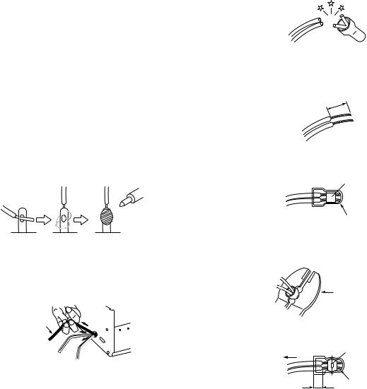
(12)Crimp type wire connectorIn such cases as when replacing the power transformer in sets where the connections between the power cord and power trans former primary lead wires are performed using crimp type connectors, if replacing the connectors is unavoidable, in order to prevent safety hazards, perform carefully and precisely according to the following steps.
•Connector part number :E03830-001
•Required tool : Connector crimping tool of the proper type which will not damage insulated parts.
•Replacement procedure
a)Remove the old connector by cutting the wires at a point close to the connector.Important : Do not reuse a connector (discard it).
cut close to connector
Fig.1-1-3
b)Strip about 15 mm of the insulation from the ends of the wires. If the wires are stranded, twist the strands to avoid frayed conductors.
15 mm
Fig.1-1-4
c)Align the lengths of the wires to be connected. Insert the wires fully into the connector.
Metal sleeve
Connector
Fig.1-1-5
d)As shown in Fig.1-1-6, use the crimping tool to crimp the metal sleeve at the center position. Be sure to crimp fully to the complete closure of the tool.
25 |
Crimping tool |
1. |
|
2. |
|
0 |
|
5. |
|
5 |
|
Fig.1-1-6
e) Check the four points noted in Fig.1-1-7.
Not easily pulled free |
Crimped at approx. center |
|
of metal sleeve |
||
|
||
|
Conductors extended |
Wire insulation recessed more than 4 mm
Fig.1-1-7
(No.YF006)1-3
1.1.2 Safety Check after Servicing
Examine the area surrounding the repaired location for damage or deterioration. Observe that screws, parts and wires have been returned to original positions, Afterwards, perform the following tests and confirm the specified values in order to verify compliance with safety standards.
(1)Insulation resistance test
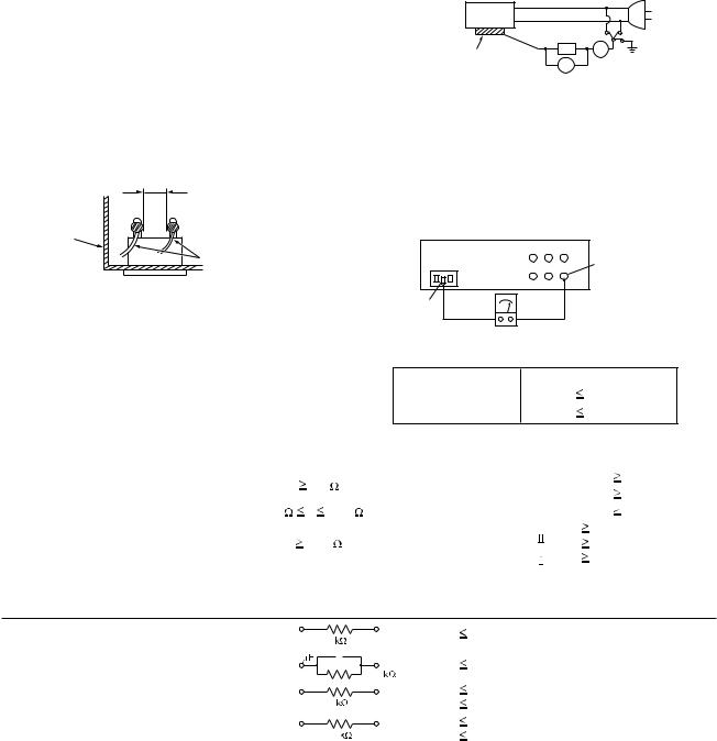
Confirm the specified insulation resistance or greater between power cord plug prongs and externally exposed parts of the set (RF terminals, antenna terminals, video and audio input and output terminals, microphone jacks, earphone jacks, etc.).See table 1 below.
(2)Dielectric strength test
Confirm specified dielectric strength or greater between power cord plug prongs and exposed accessible parts of the set (RF terminals, antenna terminals, video and audio input and output terminals, microphone jacks, earphone jacks, etc.). See Fig.1-1-11 below.
(3)Clearance distance
When replacing primary circuit components, confirm specified clearance distance (d), (d') between soldered terminals, and between terminals and surrounding metallic parts. See Fig.1-1-11 below.
d
d' Chassis 

Power cord primary wire
Fig.1-1-8
(4)Leakage current test
Confirm specified or lower leakage current between earth ground/power cord plug prongs and externally exposed accessible parts (RF terminals, antenna terminals, video and audio input and output terminals, microphone jacks, earphone jacks, etc.).
Measuring Method : (Power ON)Insert load Z between earth ground/power cord plug prongs and externally exposed accessible parts. Use an AC voltmeter to measure across both terminals of load Z. See Fig.1-1-9 and following Fig.1-1-12.
|
|
a |
b |
Externally |
Z |
A |
c |
|
|
|
|
exposed |
V |
|
|
accessible part |
|
|
|
Fig.1-1-9
(5)Grounding (Class 1 model only)
Confirm specified or lower grounding impedance between earth pin in AC inlet and externally exposed accessible parts (Video in, Video out, Audio in, Audio out or Fixing screw etc.).Measuring Method:
Connect milli ohm meter between earth pin in AC inlet and exposed accessible parts. See Fig.1-1-10 and grounding specifications.
AC inlet |
Exposed accessible part |
Earth pin |
MIlli ohm meter
Grounding Specifications
|
|
|
|
|
|
|
|
|
|
|
|
|
Region |
Grounding Impedance (Z) |
|
||||||||||
|
|
|
|
|
|
|
|
|
|
|
|
USA & Canada |
|
|
Z |
|
|
|
0.1 ohm |
||||||
|
|
|
|
|
|
|
|
|
|
|
|
|
|
|
|
|
|
|
|
|
|
|
|
|
|
|
|
|
|
|
|
|
|
|
|
|
|
Europe & Australia |
|
|
Z |
|
|
|
0.5 ohm |
||||||
|
|
|
|
|
|
|
|
|
|
|
|
|
|
|
|
Fig.1-1-10 |
|
|
|
||||||
|
|
|
|
|
|
|
|
|
|
|
|
|
|
|
|
|
|
|
|
|
|
|
|
|
|
AC Line Voltage |
Region |
|
|
|
|
|
( ) |
Dielectric Strength |
|
Clearance Distance (d), (d') |
|||||||||||||||
Insulation Resistance R |
|
||||||||||||||||||||||||
100 V |
Japan |
R |
|
|
1 M /500 V DC |
AC 1 kV 1 minute |
|
|
|
d, d' |
|
3 mm |
|||||||||||||
|
|
|
|
|
|
|
|
|
|
|
|
|
|
|
|
||||||||||
100 to 240 V |
|
|
AC 1.5 kV 1 minute |
|
|
|
d, d' |
|
4 mm |
||||||||||||||||
|
|
|
|
|
|
|
|
|
|
|
|
|
|
|
|
||||||||||
|
|
|
|
|
|
|
|
|
|
|
|
|
|
|
|
|
|
|
|||||||
110 to 130 V |
USA & Canada |
1 M |
|
|
|
R |
|
12 M /500 V DC |
AC 1 kV 1 minute |
|
|
|
d, d' |
|
3.2 mm |
||||||||||
|
|
|
|
|
|
|
|
|
|
|
|
|
|
|
|
|
|
|
|
|
|||||
110 to 130 V |
|
|
|
|
|
|
|
|
|
|
|
|
AC 3 kV 1 minute |
|
d |
|
|
|
4 mm |
||||||
Europe & Australia |
R |
10 M /500 V DC |
|
|
(Class |
) |
d' |
|
|
|
8 mm (Power cord) |
||||||||||||||
|
|
|
|
|
|
||||||||||||||||||||
200 to 240 V |
|
|
|
|
|
|
|
|
|
|
|
|
AC 1.5 kV 1 minute |
|
d' |
|
|
|
6 mm (Primary wire) |
||||||
|
|
|
|
|
|
|
|
|
|
|
|
|
|
|
(Class |
) |
|
|
|
||||||
|
|
|
|
|
|
|
|
|
|
|
|
|
|
|
|
|
|||||||||
|
|
|
|
|
|
|
|
|
Fig.1-1-11 |
|
|
|
|
|
|
|
|
|
|
|
|
|
|||
|
|
|
|
|
|
|
|
|
|
|
|
|
|
|
|
|
|
|
|
||||||
AC Line Voltage |
Region |
|
|
|
|
|
|
Load Z |
Leakage Current (i) |
|
|
|
|
|
|
a, b, c |
|||||||||
100 V |
Japan |
|
|
|
|
|
1 |
|
|
|
i |
|
1 mA rms |
|
|
Exposed accessible parts |
|||||||||
|
|
|
|
|
|
|
|
|
|
|
|
|
|
|
|
|
|
|
|
|
|
|
|||
|
|
|
|
|
|
|
|
|
|
|
|
|
|
|
|
|
|
|
|
|
|
|
|||
110 to 130 V |
USA & Canada |
0.15 |
|
|
|
|
|
|
|
i |
|
0.5 mA rms |
|
Exposed accessible parts |
|||||||||||
|
|
|
|
|
1.5 |
|
|
|
|||||||||||||||||
|
|
|
|
|
|
|
|
|
|
|
|
|
|
|
|
|
|
|
|
|
|||||
110 to 130 V |
|
|
|
|
|
|
|
|
|
|
|
|
i |
|
0.7 mA peak |
|
Antenna earth terminals |
||||||||
Europe & Australia |
|
|
|
|
|
2 |
|
|
|
i |
|
2 mA dc |
|
|
|||||||||||
|
|
|
|
|
|
|
|
|
|
|
|
|
|
|
|
|
|
|
|||||||
220 to 240 V |
|
|
|
|
|
|
|
|
|
|
|
|
|
|
|
|
|
|
|
|
|
|
|
|
|
|
|
|
|
|
|
|
|
|
|
|
i |
|
0.7 mA peak |
|
Other terminals |
||||||||||
|
|
|
|
|
|
|
|
|
|
|
|
|
|
||||||||||||
|
|
|
|
|
|
|
50 |
|
|
i |
|
2 mA dc |
|
|
|||||||||||
|
|
|
|
|
|
|
|
|
|
|
|
|
|
|
|
|
|
|
|
||||||
|
|
|
|
|
|
|
|
|
|
|
|
|
|
|
|
|
|
|
|
|
|
|
|
|
|
Fig.1-1-12
NOTE :
These tables are unofficial and for reference only. Be sure to confirm the precise values for your particular country and locality.
1-4 (No.YF006)
SECTION 2
SPECIFIC SERVICE INSTRUCTIONS
2.1DIFFERENCE LIST
The following table indicate main different points between models GR-FXM40EK, GR-FXM40EX, GR-FXM40EY, GR-FXM40EZ, GR-FXM404EX, GR-FXM404EY, GR-FXM404EZ, GR-SXM30EF, GR-SXM50EX, GR-SXM50EY and GR-SXM50EZ.
MODEL |
GR-FXM40EK |
GR-FXM40EX |
GR-FXM40EY |
GR-FXM40EZ |
GR-FXM404EX |
GR-FXM404EY |
GR-FXM404EZ |
GR-SXM30EF |
GR-SXM50EX |
GR-SXM50EY |
GR-SXM50EZ |
|
|
|
|
|
|
|
|
|
|
|
|
TAPE FORMAT |
VHS-C |
VHS-C |
VHS-C |
VHS-C |
VHS-C |
VHS-C |
VHS-C |
S-VHS-C |
S-VHS-C |
S-VHS-C |
S-VHS-C |
|
|
|
|
|
|
|
|
|
|
|
|
BODY COLOR |
SILVER |
SILVER |
SILVER |
SILVER |
MOLD |
MOLD |
MOLD |
MOLD |
SILVER |
SILVER |
SILVER |
|
|
|
|
|
BLACK |
BLACK |
BLACK |
BLACK |
|
|
|
|
|
|
|
|
|
|
|
|
|
|
|
DC LIGHT |
NO |
NO |
NO |
NO |
YES |
YES |
YES |
NO |
YES |
YES |
YES |
|
|
|
|
|
|
|
|
|
|
|
|
OSD LANGUAGE |
ENGLISH |
ENGLISH/ |
ENGLISH/ |
ENGLISH/ |
ENGLISH/ |
ENGLISH/ |
ENGLISH/ |
ENGLISH |
ENGLISH/ |
ENGLISH/ |
ENGLISH/ |
|
|
RUSSIAN |
RUSSIAN |
RUSSIAN |
RUSSIAN |
RUSSIAN |
RUSSIAN |
|
RUSSIAN |
RUSSIAN |
RUSSIAN |
AC CORD |
BS PLUG |
CEE PLUG |
CEE PLUG |
CEE PLUG |
CEE PLUG |
CEE PLUG |
CEE PLUG |
CEE PLUG |
CEE PLUG |
CEE PLUG |
CEE PLUG |
|
|
|
|
|
|
|
|
|
|
|
|
(No.YF006)1-5
SECTION 3
DISASSEMBLY
3.1BEFORE ASSEMBLY AND DISASSEMBLY
3.1.1 Precautions
•Be sure to disconnect the power supply unit prior to mounting and soldering of parts.
•Prior to removing a component part that needs to disconnect its connector(s) and its screw(s), first disconnect the wire(s) from the connector(s), and then remove the screw(s).
•When connecting/disconnecting wires, pay enough attention not to damage the connectors.
•When inserting the flat wire to the connector, pay attention to the direction of the flat wire.
•Be careful in removing the parts to which some spacer or shield is attached for reinforcement or insulation.
•When replacing chip parts (especially IC parts), first remove the solder completely to prevent peeling of the pattern.
•Tighten screws properly during the procedures. Unless specified otherwise, tighten screws at a torque of 0.196N·m (2.0kgf·cm). However, 0.196N·m (2.0kgf·cm) is a value at the
time of production. At the time of service, perform the procedure at a torque 10% less than 0.196N·m (2.0kgf·cm). (See "SERVICE NOTE" as for tightening torque.)
3.1.2 Destination of connectors
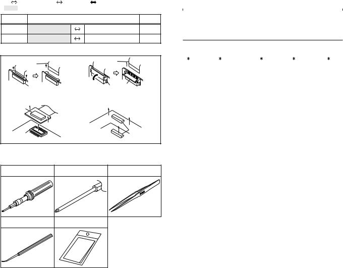
Two kinds of double-arrows in connection tables respectively show kinds of connector/wires.
: Flat wire |
: Wire |
: Board to board (B-B) |
||||
: The connector of the side to remove |
|
|||||
CONN. No. |
|
CONNECTOR |
|
PIN No. |
||
CN2a |
MAIN |
CN101 |
MONI/BW |
CN761 |
40 |
|
CN2b |
MAIN |
CN103 |
MIC |
CN762 |
2 |
|
3.1.3 Disconnection of connectors (Wires) |
|
|||||
|
Wire |
|
Wire |
|
|
|
|
|
|
|
|
||
|
FPC Connector |
|
Lock |
|
||
|
FPC Connector |
|
||||
|
|
|
|
|||
· Pull both ends of the connector in the arrow |
· Extend the locks in the direction of the arrow for |
|||||
direction, remove the lock and disconnect the flat |
||||||
unlocking and then pull out the wire. After |
||||||
wire. |
|
|
||||
|
|
removing the wire, immediately restore the locks |
||||
|
|
|
||||
|
|
|
to their original positions because the locks are |
|||
B-B Connector |
|
|
apt to come off the connector. |
|
||
|
|
|
|
|
||
|
|
|
|
B-B Connector |
||
B-B Connector |
|
|
|
|
||
· Pull the both ends of the board in the direction of the arrow, and remove the B-B Connector.
Fig.3-1-1
3.1.4 Tools required for disassembly and assembly
Torque driver |
Bit |
Tweezers |
YTU94088 |
YTU94088-003 |
P-895 |
Chip IC replacement jig |
Cleaning cloth |
|
PTS40844-2 |
KSMM-01 |
|
|
Fig.3-1-2 |
|
1-6 (No.YF006) |
|
|
•Torque driver
Be sure to use to fastening the mechanism and exterior parts because those parts must strictly be controlled for tightening torque.
•Bit
This bit is slightly longer than those set in conventional torque drivers.
•Tweezers
To be used for removing and installing parts and wires.
•Chip IC replacement jig
To be used for replacement of IC.
•Cleaning cloth
Recommended cleaning cloth to wipe down the video heads, mechanism (tape transport system), optical lens surface.
3.2ASSEMBLY AND DISASSEMBLY OF MAIN PARTS
3.2.1 Assembly and disassembly
When reassembling, perform the step(s) in reverse order.
STEP |
PART |
Fig. |
POINT |
NOTE |
|
No. |
No. |
||||
|
|
|
|||
|
|
|
|
|
|
|
|
|
|
|
|
[1] |
TOP COVER ASSY |
Fig.C1 |
S1,2(L1) |
- |
|
[2] |
UPPER ASSY |
Fig.C2-1 |
S2a,2(S2b),3(S2c) |
- |
|
|
(Inc. VF ASSY, |
|
2(S2d),S2e,S2c |
|
|
|
SPEAKER/MONITOR) |
|
L2,CN2a,b |
|
|
[8] |
VF ASSY |
Fig.C2-2 |
2(S8),L8,CN8a |
NOTE 8a |
|
|
|
|
|
NOTE 8b |
|
( 1) |
( 2) |
( 3) |
( 4) |
( 5) |
( 1) Order of steps in Procedure
When reassembling, preform the step(s) in the reverseorder. These numbers are also used as the identification (location) No. of parts Figures.
( 2) Part to be removed or installed.
( 3) Fig. No. showing Procedure or Part Location. C = CABINET
( 4) Identification of part to be removed, unhooked, unlocked, released, unplugged, unclamped or unsoldered.
S = Screw
L = Lock, Release, Hook SD = Solder
CN = Connector
[Example]
•4 (S1a) = Remove 4 S1a screws.
•3 (L1a) = Disengage 3 L1a hooks.
•2 (SD1a) = Unsolder 2 SD1a points.
•CN1a = Remove a CN1a connector.
( 5) Adjustment information for installation.

3.2.2 ASSEMBLY/DISASSEMBLY OF CABINET PARTS AND ELECTRICAL PARTS
zDisassembly procedure
STEP |
PART NAME |
Fig. |
POINT |
NOTE |
|
No. |
No. |
||||
|
|
|
|||
|
|
|
|
|
|
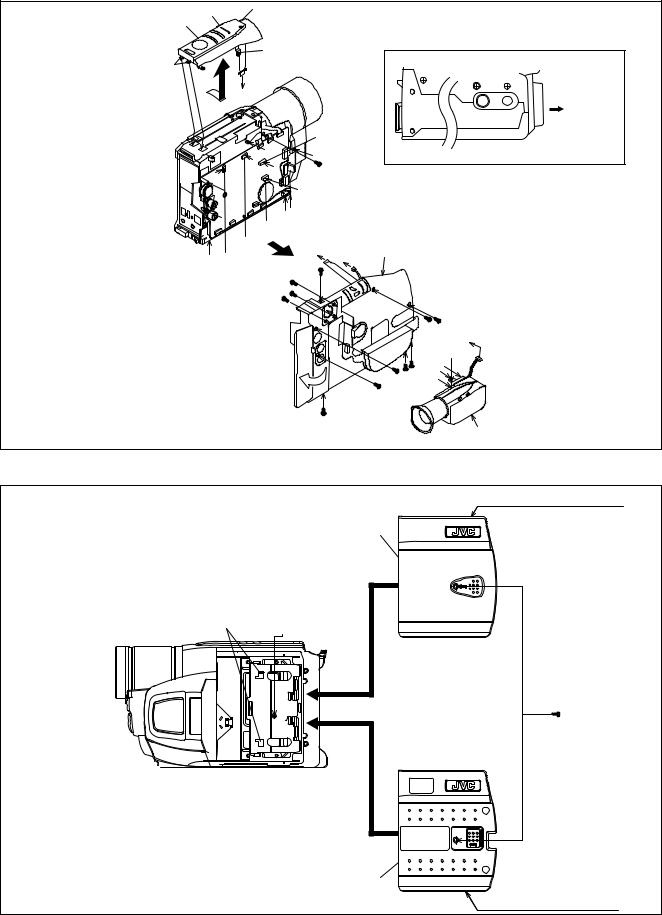
[1] |
LOWER CASE ASSEMBLY |
Fig.C1 |
8(S1),CN1a,b,c |
- |
|
[2] |
B/W VF ASSEMBLY |
|
3(S2) |
- |
|
[3] |
TOP OPE UNIT(S) |
|
CN3,(S3),(L3a),(L3b),2(L3d) |
- |
|
|
TOP OPE UNIT(M) |
|
CN3,(S3),(L3a),(L3b),(L3c),2(L3d) |
|
|
[4] |
CASE COVER(S) ASSEMBLY |
Fig.C2 |
(S4),2(L4) |
- |
|
|
CASE COVER(M) ASSEMBLY |
|
|
|
|
[5] |
UPPER CASE(S) ASSEMBLY |
Fig.C3 |
6(S5a),(S5b),(L5) |
NOTE 5 |
|
|
UPPER CASE(M) ASSEMBLY |
|
CN5,6(S5a),(S5b) |
|
|
|
Inc. MONITOR ASSEMBLY |
|
|
|
|
[6] |
COVER (UPPER/M) ASSEMBLY |
Fig.C4 |
3(S6) |
- |
|
[7] |
MONITOR ASSEMBLY |
|
S7a,L7,SHEET(FPC),2(S7b) |
NOTE 7a,b,c,d |
|
[8] |
FRONT COVER ASSEMBLY |
Fig.C5 |
CN8a,CN8b,(S8),L8a,L8b |
NOTE 8a,b |
|
|
Inc. DC LIGHT,MIC |
|
|
|
|
[9] |
DC LIGHT ASSEMBLY |
|
2(L9) |
- |
|
[10] |
MIC |
|
S10 |
- |
|
[11] |
FRONT FRAME SA |
|
2(S11) |
- |
|
|
|
|
|
|
NOTE 5 :
Take care not to break or damage the FRAME.
NOTE 7a :
Take care not to cut the FPC wire.
NOTE 7b :
Insert and attach the SHEET(FPC) between the MONITOR FPC and the UPPER CASE(M)ASSEMBLY.
NOTE 7c :
Attachment of the FPC
NOTE 7d :
For disassembly of the MONITOR ASSEMBLY, refer to 2.4 ASSEMBLY AND DISASSEMBLY OF [7]MONITOR ASSEMBLY (CABINET PARTS).
NOTE 8a :
Take care not to damage the OP BLOCK ASSEMBLY when and after the FRONT CASE ASSEMBLY is removed.
NOTE 8b :
Attachment of the WIRE
zDestination of connectors
CN.NO. |
|
CONNECTOR |
|
PIN |
||
|
|
NO. |
||||
|
|
|
|
|
|
|
|
|
|
|
|
|
|
CN1a |
MAIN |
CN27 |
|
SPEAKER |
- |
2 |
CN1b |
MAIN |
CN13 |
|
ZOOM UNIT |
- |
14 |
CN1c |
MAIN |
CN12 |
|
B/W VF ASSEMBLY |
- |
3 |
CN3 |
MAIN |
CN18 |
|
TOP OPE UNIT |
- |
13 |
CN5 |
MAIN |
CN16 |
|
MONITOR ASSEMBLY CN7601 |
25 |
|
CN8a |
MAIN |
CN6 |
|
DC LIGHT |
- |
2 |
CN8b |
MAIN |
CN8 |
|
MIC |
- |
2 |
(No.YF006)1-7
[3] |
L3c |
|
|
|
L3b |
|
|
|
|
|
|
|
|
|
|
|
|
|
|
|
|
|
|
|
L3a |
|
|
|
|
|
<BOTTOM SIDE> |
|
|||||
|
|
|
|
|
|
|
|
|
|
|
|
|
|
|
|
|
|
|
L3d |
|
|
|
|
|
|
|
|
|
|
|
|
|
6 |
|
7 |
8 |
OP BLOCK |
|
|
|
|
|
D |
|
|
|
|
|
|
|
|
|
|
|
||
|
|
|
|
|
|
|
|
|
|
|
|
|
|
|
|
ASSEMBLY |
||
|
|
|
|
|
|
v |
|
|
CN3 |
|
|
|
|
|
|
|
|
|
|
|
|
|
|
|
|
|
w 12 |
|
|
|
|
|
|
|
|
||
|
|
|
|
|
|
F |
|
|
|
|
|
|
|
|
|
|
||
|
E |
|
|
|
D |
|
|
|
(S3) |
|
|
|
|
|
|
|
|
|
|
|
u |
|
|
|
G |
|
|
|
|
|
|
|
|
|
|
||
|
|
|
|
|
|
|
|
|
|
|
|
|
|
|
|
|
||
|
|
t |
|
|
|
yz |
|
|
|
|
|
|
|
|
|
|
|
|
|
|
|
|
CN1a |
|
|
|
|
|
|
|
|
|
|
|
|
||
|
|
|
|
|
|
|
|
|
|
|
[1] |
|
|
|
|
|
|
|
|
x |
|
|
CN1b |
|
3 F |
G |
|
|
|
|
|
|
|
||||
|
CN1c |
|
|
|
|
|
|
|
|
|
|
|||||||
|
|
9 (S2) |
(S1) |
|
|
|
|
|
|
|
|
|
||||||
|
|
|
|
|
|
|
|
|
|
|
|
|
|
|
||||
|
|
|
|
|
|
10 (S2) |
q |
r |
s1 |
v |
|
w |
|
|
|
|
||
|
|
|
|
|
|
11 (S2) |
p |
|
|
|
|
|
|
|
|
|||
|
|
|
|
|
|
|
|
|
|
|
|
|
|
|
||||
|
|
|
|
|
|
|
|
E |
|
|
|
|
|
1 |
|
|
||
|
|
|
|
|
|
|
|
|
|
|
|
|
|
|
|
|
||
|
|
|
|
|
|
|
|
|
u |
|
|
|
|
2 |
(S1) |
|
|
|
|
|
|
|
|
|
|
|
|
|
|
|
|
|
z (S1) |
E |
|
|
|
|
|
|
|
|
|
|
|
|
t |
|
|
|
y |
8 |
|
s1 |
|
|
|
|
|
|
|
|
|
|
|
|
|
|
4 |
7 |
(S1)qr |
|
|
|
|
|
|
|
|
|
|
|
|
|
|
|
|
p |
|
|
|
|
||
|
|
|
|
|
|
|
|
|
|
x |
5 |
(S1)(S1) |
|
|
|
|
||
|
|
|
|
|
|
|
|
|
6 |
|
(S1) |
|
|
|
|
|
|
|
|
|
|
|
|
|
|
|
|
|
|
|
|
|
|
|
|
|
|
|
|
|
|
|
|
|
|
(S1) |
|
|
|
|
|
[2] |
|
|||
|
|
|
|
|
|
|
|
|
|
|
|
|
|
|
|
|
||
|
|
|
|
|
|
|
|
|
Fig.C1 |
|
|
|
|
|
|
|
|
|
|
|
|
|
|
|
|
|
|
|
|
|
|
|
|
|
|
<S : SHOOTING MODEL> |
|
|
|
|
|
|
|
|
|
|
|
|
[4] |
|
|
|
|
|
|
|
|
|
|
|
|
|
|
|
|
|
|
|
|
|
|
|
aa |
|
|
|
|
|
L4 |
|
aa |
|
|
|
|
|
|
|
|
|
|
|
||
|
|
|
|
|
|
|
|
|
|
|
|
|
|
|
|
|
||
|
|
|
|
|
|
|
|
|
|
|
|
|
|
|
|
|
|
12 |
|
|
|
|
|
|
|
|
|
|
|
|
|
|
|
|
|
|
(S4) |
|
|
|
|
|
|
|
|
|
|
|
|
|
|
|
|
aa |
|
|
|
|
|
|
|
|
|
|
|
|
|
[4] |
|
|
|
|
|
|
|
|
|
|
|
|
|
|
|
|
|
|
|
|
|
|
|
|
<M : MONITOR MODEL> |
|
|
|
|
|
|
|
|
|
|
Fig.C2 |
|
|
|
|
|
|
|
|
|
1-8 (No.YF006) |
|
|
|
|
|
|
|
|
|
|
|
|
|
|
|
|
|
|
Loading...