


GR-DVL510KR
Table of contents
 Loading...
DIGITAL VIDEO CAMERA
GR-DVL915
GR-DVL815
GR-DVL510
GR-DVL310
ENGLISH
CONTENTS
AUTOMATIC
DEMONSTRATION
GETTING STARTED
VIDEO RECORDING &
PLAYBACK
VIDEO RECORDING ............ 16 – 20
VIDEO PLAYBACK.............. 21 – 24
DIGITAL STILL CAMERA (D.S.C.)
RECORDING &
PLAYBACK
D.S.C. RECORDING ............ 26 – 27
D.S.C. PLAYBACK .............. 28 – 36
ADVANCED
FEATURES
7 – 14
15 – 24
25 – 36
37 – 69
6
Please visit our Homepage on the World Wide Web and
answer our Consumer Survey (in English only):
http://www.jvc-victor.co.jp/english/index-e.html
The camcorder illustrations
appearing in this instruction
manual are of the GR-DVL915.
INSTRUCTIONS
For Customer Use:
Enter below the Model No. and Serial No. which is located on the
bottom of cabinet. Retain this information for future reference.
Model No.
Serial No.
FOR RECORDING ................ 38 – 45
USING THE MENU FOR
DETAILED ADJUSTMENT ...... 46 – 51
DUBBING ......................... 52 – 55
USING THE REMOTE
CONTROL UNIT ................ 56 – 67
SYSTEM CONNECTIONS ........ 68 – 69
REFERENCES
DETAILS ................................... 71
TROUBLESHOOTING ............ 72 – 76
USER MAINTENANCE ................... 77
INDEX ............................. 78 – 84
CAUTIONS ........................ 85 – 87
TERMS ............................ 88 – 89
SPECIFICATIONS ................. 90 – 91
The D.S.C. (Digital Still Camera) features
are available on GR-DVL915, GR-DVL815
and GR-DVL510.
LYT0722-001A
70 – 91
EN
2 EN
Dear Customer,
Thank you for purchasing this digital video camera. Before use, please read the safety information and
precautions contained in the following pages to ensure safe use of this product.
Using This Instruction Manual
•All major sections and subsections are listed in the Table Of Contents on the cover page.
•Notes appear after most subsections. Be sure to read these as well.
•Basic and advanced features/operation are separated for easier reference.
It is recommended that you . . .
.... refer to the Index ( pgs. 78 – 84) and familiarize yourself with button locations, etc. before use.
.... read thoroughly the Safety Precautions and Safety Instructions that follow. They contain extremely
important information regarding the safe use of this product.
You are recommended to carefully read the cautions on pages 85 through 87 before use.
SAFETY PRECAUTIONS
CAUTION
RISK OF ELECTRIC SHOCK
DO NOT OPEN
CAUTION: TO REDUCE THE RISK OF ELECTRIC SHOCK,
DO NOT REMOVE COVER (OR BACK).
NO USER-SERVICEABLE PARTS INSIDE.
REFER SERVICING TO QUALIFIED SERVICE PERSONNEL.
The lightning flash with arrowhead symbol, within an
equilateral triangle, is intended to alert the user to the
presence of uninsulated "dangerous voltage" within the
product's enclosure that may be of sufficient magnitude
to constitute a risk of electric shock to persons.
The exclamation point within an equilateral triangle is
intended to alert the user to the presence of important
operating and maintenance (servicing) instructions in
the literature accompanying the appliance.
CAUTIONS:
● This camcorder is designed to be used with NTSC-type color television signals. It cannot be used for
playback with a television of a different standard. However, live recording and LCD monitor/viewfinder
playback are possible anywhere.
● Use the JVC BN-V408U/V416U/V428U battery packs and, to recharge them or to supply power to the
camcorder from an AC outlet, use the provided multi-voltage AC Adapter. (An appropriate conversion
adapter may be necessary to accommodate different designs of AC outlets in different countries.)
WARNING:
TO REDUCE THE RISK OF FIRE
OR ELECTRIC SHOCK, DO
NOT EXPOSE THIS APPARATUS
TO RAIN OR MOISTURE.
NOTES:
●
The rating plate (serial number plate) and safety
caution are on the bottom and/or the back of
the main unit.
●
The rating information and safety caution of the
AC Adapter are on its upper and lower sides.
EN3
When the equipment is installed in a cabinet or on a shelf, make sure that it has sufficient space on all
sides to allow for ventilation (10 cm (3-15/16") or more on both sides, on top and at the rear).
Do not block the ventilation holes.
(If the ventilation holes are blocked by a newspaper, or cloth etc. the heat may not be able to get out.)
No naked flame sources, such as lighted candles, should be placed on the apparatus.
When discarding batteries, environmental problems must be considered and the local rules or laws
governing the disposal of these batteries must be followed strictly.
The apparatus shall not be exposed to dripping or splashing.
Do not use this equipment in a bathroom or places with water.
Also do not place any containers filled with water or liquids (such as cosmetics or medicines, flower vases,
potted plants, cups etc.) on top of this unit.
(If water or liquid is allowed to enter this equipment, fire or electric shock may be caused.)
IMPORTANT SAFETY INSTRUCTIONS
(1) Read these instructions.
(2) Keep these instructions.
(3) Heed all warnings.
(4) Follow all instructions.
(5) Do not use this apparatus near water.
(6) Clean only with dry cloth.
(7) Do not block any ventilation openings.
Install in accordance with the
manufacturer’s instructions.
(8) Do not install near any heat sources such
as radiators, heat registers, stoves, or other
apparatus (including amplifiers) that
produce heat.
(9) Only use attachments/accessories specified
by the manufacturer.
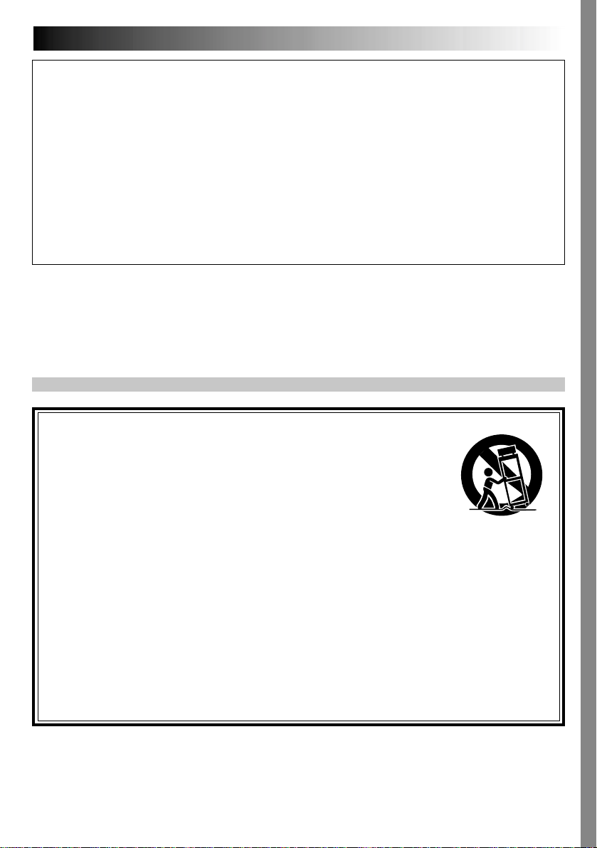
(10) Use only with the cart,
stand, tripod, bracket,
or table specified by
the manufacturer, or
sold with the
apparatus. When a
cart is used, use
caution when moving
the cart/apparatus combination to avoid
injury from tip-over.
(11) Unplug this apparatus during lightning
storms or when unused for long periods of
time.
(12) Refer all servicing to qualified service
personnel. Servicing is required when the
apparatus has been damaged in any way,
such as power-supply cord or plug is
damaged, liquid has been spilled or objects
have fallen into the apparatus, the apparatus
has been exposed to rain or moisture, does
not operate normally, or has been dropped.

4 EN
SAFETY PRECAUTIONS
Do not point the lens or the viewfinder directly into the sun. This can cause eye injuries, as well as
lead to the malfunctioning of internal circuitry. There is also a risk of fire or electric shock.
CAUTION!
The following notes concern possible physical damage to the camcorder and to the user.
When carrying, be sure to always securely attach and use the provided shoulder strap. Carrying
or holding the camcorder by the viewfinder and/or the LCD monitor can result in dropping the
unit, or in a malfunction.
Take care not to get your finger caught in the cassette holder cover. Do not let children operate the
camcorder, as they are particularly susceptible to this type of injury.
Do not use a tripod on unsteady or unlevel surfaces. It could tip over, causing serious damage to
the camcorder.
CAUTION!
Connecting cables (Audio/Video, S-Video, etc.) to the camcorder and leaving the unit on top of the
TV is not recommended, as tripping on the cables will cause the camcorder to fall, resulting in
damage.
This camcorder is designed exclusively for the digital video cassette, SD Memory Card and
MultiMediaCard. Only cassettes marked “
“
” can be used with this unit.
” and memory cards* marked “ ” or
Before recording an important scene . . .
.... make sure you only use cassettes with the Mini DV mark .
.... make sure you only use memory cards* with the mark
.... remember that this camcorder is not compatible with other digital video formats.
.... remember that this camcorder is intended for private consumer use only. Any commercial use
without proper permission is prohibited. (Even if you record an event such as a show,
performance or exhibition for personal enjoyment, it is strongly recommended that you obtain
permission beforehand.)
*Memory cards can be used with GR-DVL915/DVL815/DVL510 only.
or .
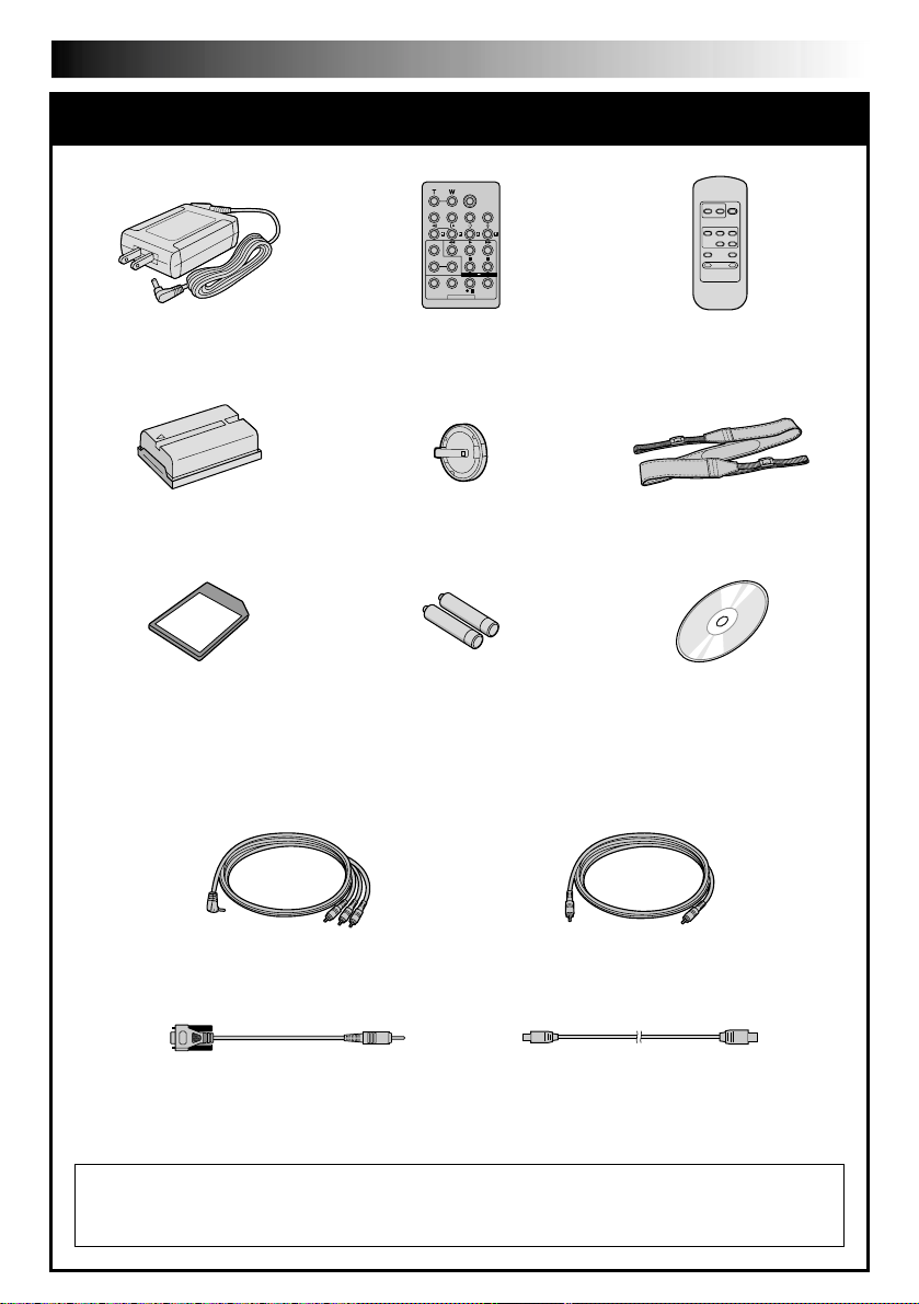
PROVIDED ACCESSORIES
EN5
•AC Adapter
AP-V10U
•Battery Pack
BN-V408U
•MultiMediaCard
16 MB (GR-DVL915/
DVL815 only) or
8 MB (GR-DVL510 only)
(Already inserted in the
camcorder)
•Audio/Video Cable
(ø3.5 mini-plug to RCA plug)
•Remote Control Unit
RM-V716U (GR-DVL915/
DVL815 only)
•Lens Cap ( pg. 6 for
attachment)
(for remote control unit)
•Remote Control Unit
RM-V715U (GR-DVL510/
DVL310 only)
•Shoulder Strap
•CD-ROM•AAA (R03) Battery x 2
•Editing Cable
(GR-DVL915/DVL815 only)
•PC Connection Cable
(GR-DVL310 only)
NOTE:
In order to maintain optimum performance of the camcorder, provided cables may be equipped
with one or more core filter.
•USB Cable (GR-DVL915/
DVL815/DVL510 only)
6 EN
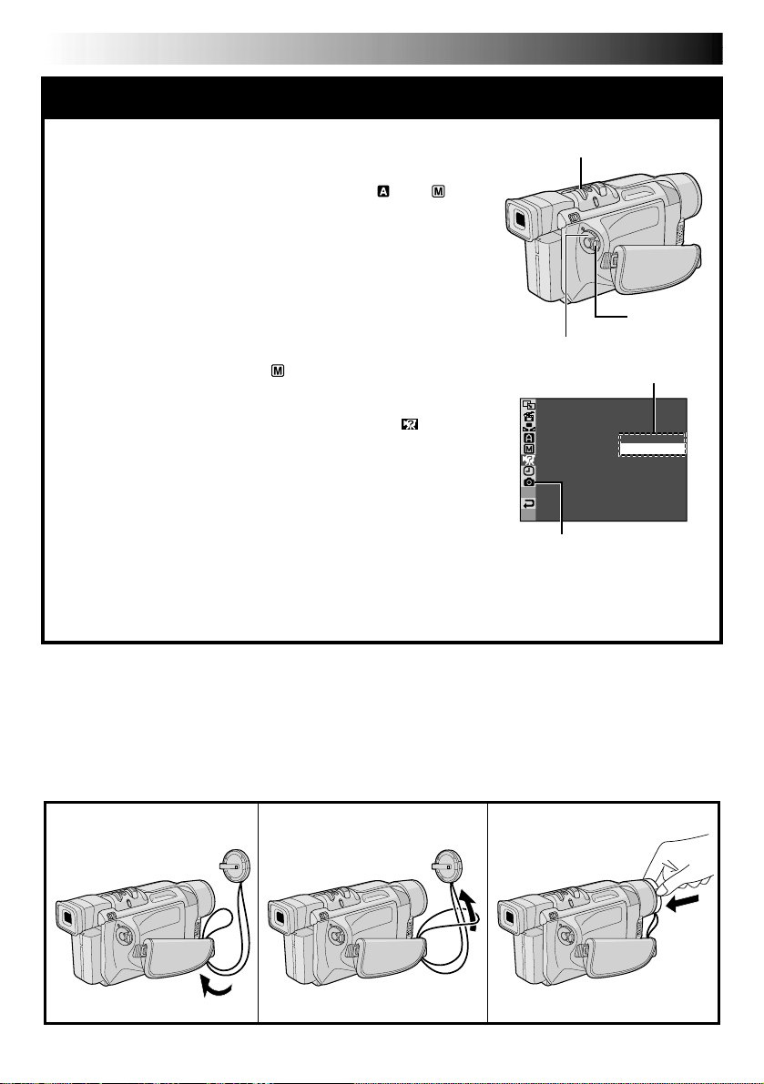
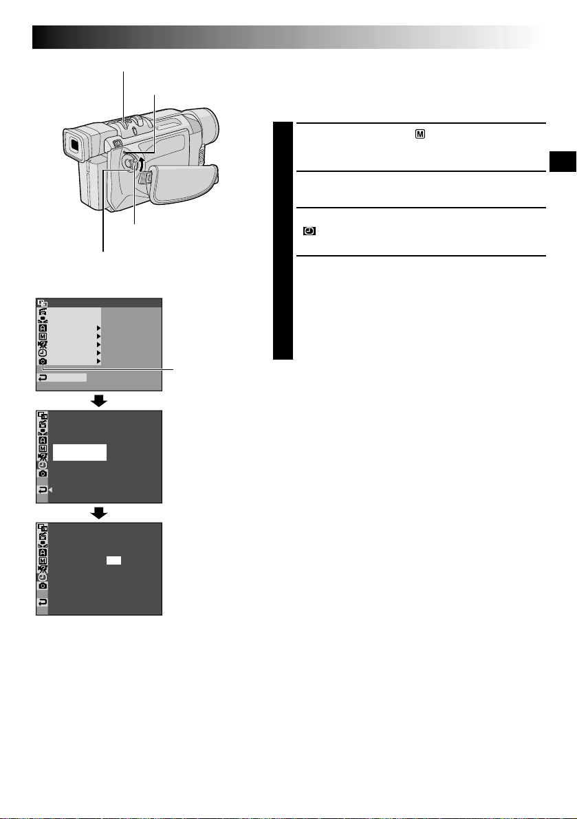
MOD EDEMO –ONOFF
AUTOMATIC DEMONSTRATION
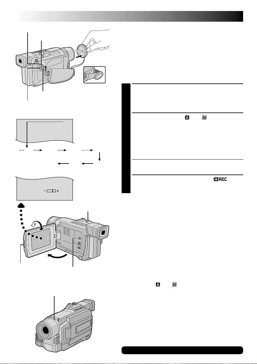
Automatic Demonstration takes place when “DEMO MODE”
is set to “ON” (factory-preset).
Available when the Power Switch is set to “
no cassette is in the camcorder.
Performing any operation during the demonstration stops
the demonstration temporarily. If no operation is performed
for more than 1 minute after that, the demonstration will
resume.
“DEMO MODE” remains “ON” even if the camcorder
power is turned off.
To cancel Automatic Demonstration:
1. Set the Power Switch to “
Lock Button located on the switch and press the MENU/
BRIGHT wheel in. The Menu Screen appears.
2. Rotate the MENU/BRIGHT wheel to select “
and press it. The SYSTEM Menu appears.
3. Rotate the MENU/BRIGHT wheel to select “DEMO
MODE” and press it. The Sub Menu appears.
4. Rotate the MENU/BRIGHT wheel to select “OFF” and
press it.
5. Rotate the MENU/BRIGHT wheel to select “
and press it twice.
NOTE:
If you do not detach the Lens Cap, you cannot see the actual changes of the Automatic Demonstration
activated on the LCD monitor or viewfinder.
The normal screen appears.
” while pressing down the
” or “ ” and
SYSTEM”
1
RETURN”,
MENU/BRIGHT Wheel
Lock Button
Power Switch
Sub Menu
GR-DVL915/DVL815/DVL510
only
How To Attach The Lens Cap
To protect the lens, attach the provided lens cap to the camcorder as shown in the illustration.
NOTE:
To confirm the lens cap is on correctly make sure the cap is flush to the camera.
132

GETTING STARTED
EN7
GETTING STARTED
CONTENTS
Power.................................................. 8 – 9
Grip Adjustment ......................................... 10
Viewfinder Adjustment.................................. 10
Shoulder Strap Attachment ............................. 10
Tripod Mounting.......................................... 10
Date/Time Settings...................................... 11
Loading/Unloading A Cassette ......................... 12
Recording Mode Setting ................................. 13
Loading A Memory Card
(GR-DVL915/DVL815/DVL510 only) ........................ 14
Picture Quality Mode Setting
(GR-DVL915/DVL815/DVL510 only) ........................ 14
8 EN
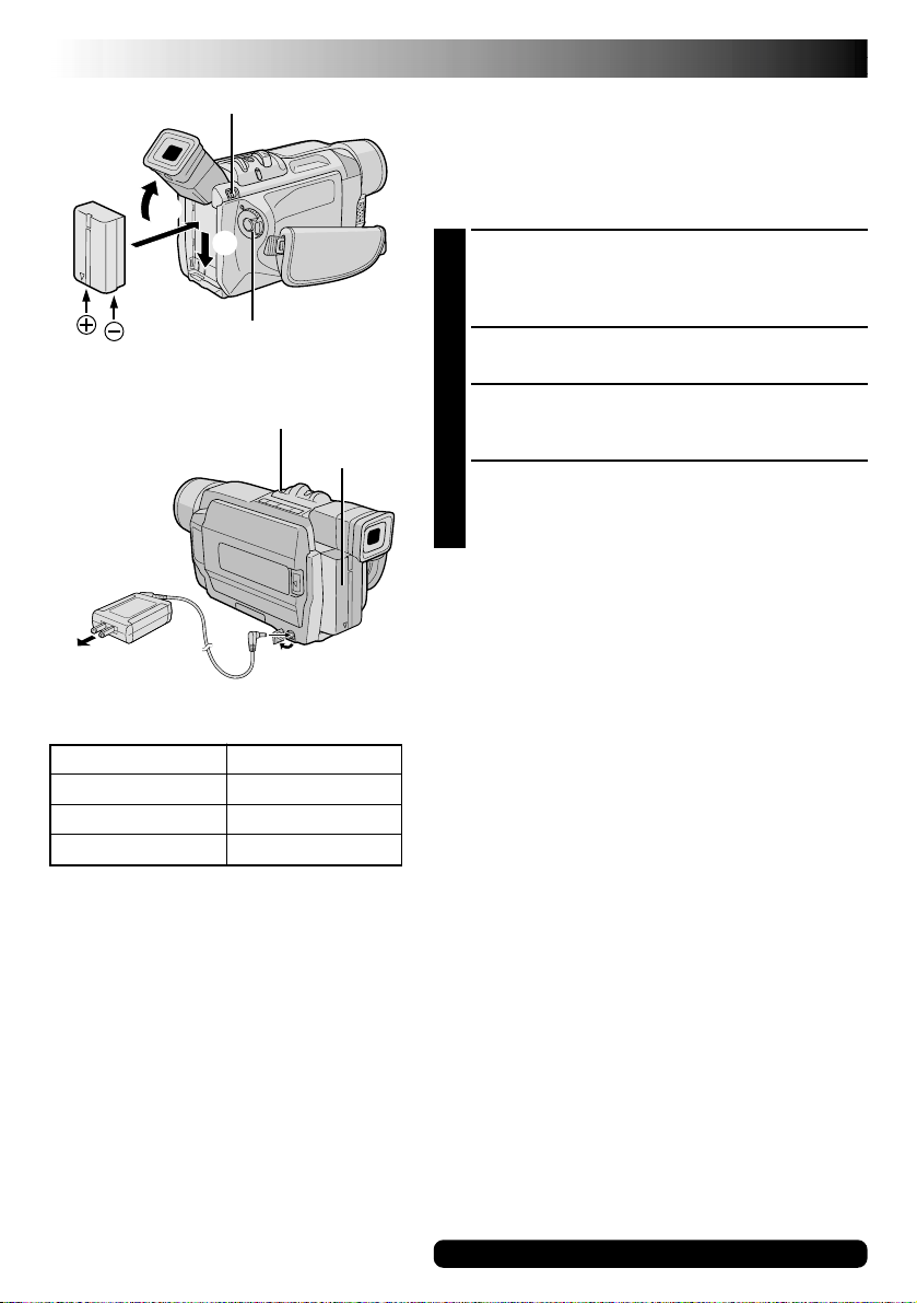
BAT. RELEASE Switch
1
3
2
Power Switch
GETTING STARTED
(cont.)
Power
This camcorder’s 2-way power supply system lets you
choose the most appropriate source of power. Do not use
provided power supply units with other equipment.
CHARGING THE BATTERY PACK
Tilt the viewfinder upward 1. With the arrow on the
1
battery pack pointing downward, push the battery
pack slightly against the battery pack mount 2, then
slide down the battery pack until it locks in place 3.
Set the Power Switch to “OFF”. Connect the AC
2
Adapter to the camcorder 4.
AC Adapter
5
To AC outlet
Battery pack
BN-V408U
BN-V416U (optional)
BN-V428U (optional)
CHARGE Lamp
Battery pack
To D C
4
connector
Charging time
approx. 1 hr. 30 min.
approx. 2 hrs.
approx. 3 hrs. 20 min.
Plug the AC Adapter into an AC outlet 5.
3
The CHARGE lamp on the camcorder blinks to
indicate charging has started.
When the CHARGE lamp stops blinking but stays lit,
4
charging is finished. Unplug the AC Adapter from the
AC outlet. Disconnect the AC Adapter from the
camcorder.
To Detach The Battery Pack . . .
.... slide BAT. RELEASE and pull out the battery pack.
NOTES:
●
If the protective cap is attached to the battery pack,
remove it first.
●
During charging, the camcorder cannot be operated.
●
Charging is not possible if the wrong type of battery is
used.
●
When charging the battery pack for the first time or after
a long storage period, the CHARGE lamp may not light.
In this case, remove the battery pack from the
camcorder, then try charging again.
●
If the battery operation time remains extremely short
even after having been fully charged, the battery is worn
out and needs to be replaced. Please purchase a new
one.
●
Using the optional AA-V40U AC Power Adapter/
Charger, you can charge the BN-V408U/V416U/V428U
battery pack without the camcorder. However, it cannot
be used as an AC adapter.
For other notes, pg. 71
EN9
ATTENTION:
Before detaching the power source, make
sure that the camcorder’s power is turned
off. Failure to do so can result in a
camcorder malfunction.
NOTES:
●
Recording time is reduced significantly under
the following conditions:
•
Zoom or Record-Standby mode is engaged
repeatedly.
•
The LCD monitor is used repeatedly.
•
The playback mode is engaged repeatedly.
●
Before extended use, it is recommended that
you prepare enough battery packs to cover 3
times the planned shooting time.
INFORMATION:
The extended-use battery pack kit is a set composed of a battery pack and AC Power Adapter/Charger:
VU-V840 KIT : BN-V840U battery pack & AA-V15U AC Power Adapter/Charger
VU-V856 KIT : BN-V856U battery pack & AA-V80U AC Power Adapter/Charger
Read the kit's instruction manual before using.
Neither BN-V840U nor BN-V856U can be charged by using the AC Adapter provided with this camcorder. Use only
the AA-V15U AC Power Adapter/Charger for BN-V840U battery pack and only AA-V80U AC Power Adapter/Charger
for BN-V856U battery pack. Also, by using the optional JVC VC-VBN856U DC Cord, it will be possible to connect
BN-V840U or BN-V856U battery packs to the camcorder and supply power directly to the camcorder.
USING THE BATTERY PACK
Perform step 1 of “CHARGING THE BATTERY PACK”
( pg. 8).
Approximate recording time (unit: min.)
Battery pack
BN-V408U
BN-V416U
(optional)
BN-V428U
(optional)
BN-V840U
(optional)
BN-V856U
(optional)
( ) : when the video light is on
LCD monitor on
1 hr.
(35 min.)
2 hrs.
(1 hr. 10 min.)
3 hrs. 30 min.
(2 hrs.)
5 hrs.
(2 hrs. 55 min.)
7 hrs.
(4 hrs.)
Viewfinder on
1 hr. 15 min.
(40 min.)
2 hrs. 30 min.
(1 hr. 20 min.)
4 hrs. 20 min.
(2 hrs. 20 min.)
6 hrs. 15 min.
(3 hrs. 20 min.)
8 hrs. 40 min.
(4 hrs. 40 min.)
USING AC POWER
Use the AC Adapter (connect as shown in the illustration).
AC Adapter
To AC outlet
To DC connector
NOTES:
●
The provided AC Adapter features automatic voltage
selection in the AC range from 110 V to 240 V.
●
For other notes, pg. 71.
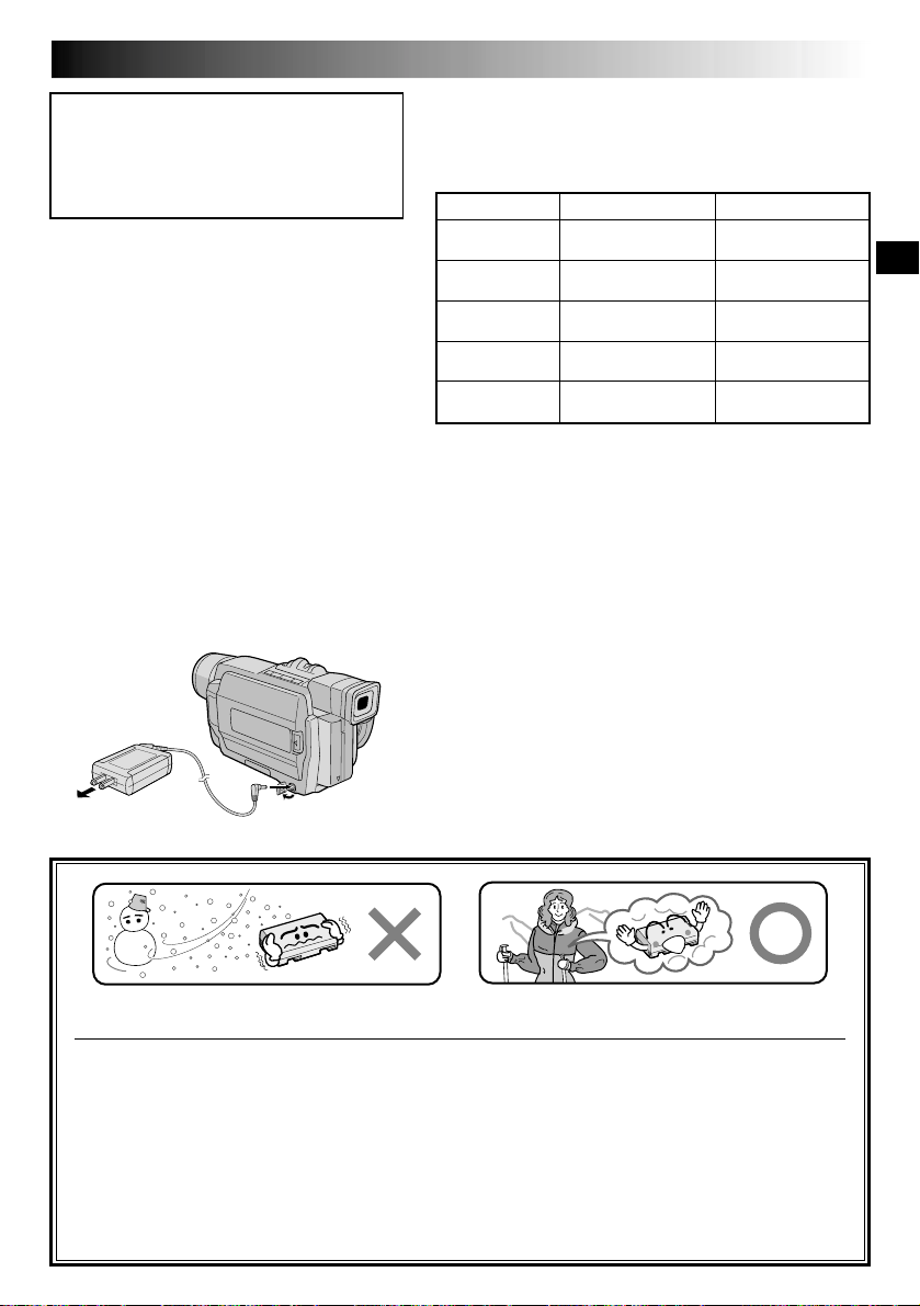
Lithium-ion is vulnerable in colder temperatures.
About Batteries
DANGER! Do not attempt to take the batteries apart, or expose them to flame or excessive heat, as it may
cause a fire or explosion.
WARNING! Do not allow the battery or its terminals to come in contact with metals, as this can result in a
short circuit and possibly start a fire.
The Benefits Of Lithium-Ion Batteries
Lithium-ion battery packs are small but have a large power capacity. However, when one is exposed to cold
temperatures (below 10°C/50°F), its usage time becomes shorter and it may cease to function. If this happens,
place the battery pack in your pocket or other warm, protected place for a short time, then re-attach it to the
camcorder. As long as the battery pack itself is not cold, it should not affect performance.
(If you’re using a heating pad, make sure the battery pack does not come in direct contact with it.)
10 EN
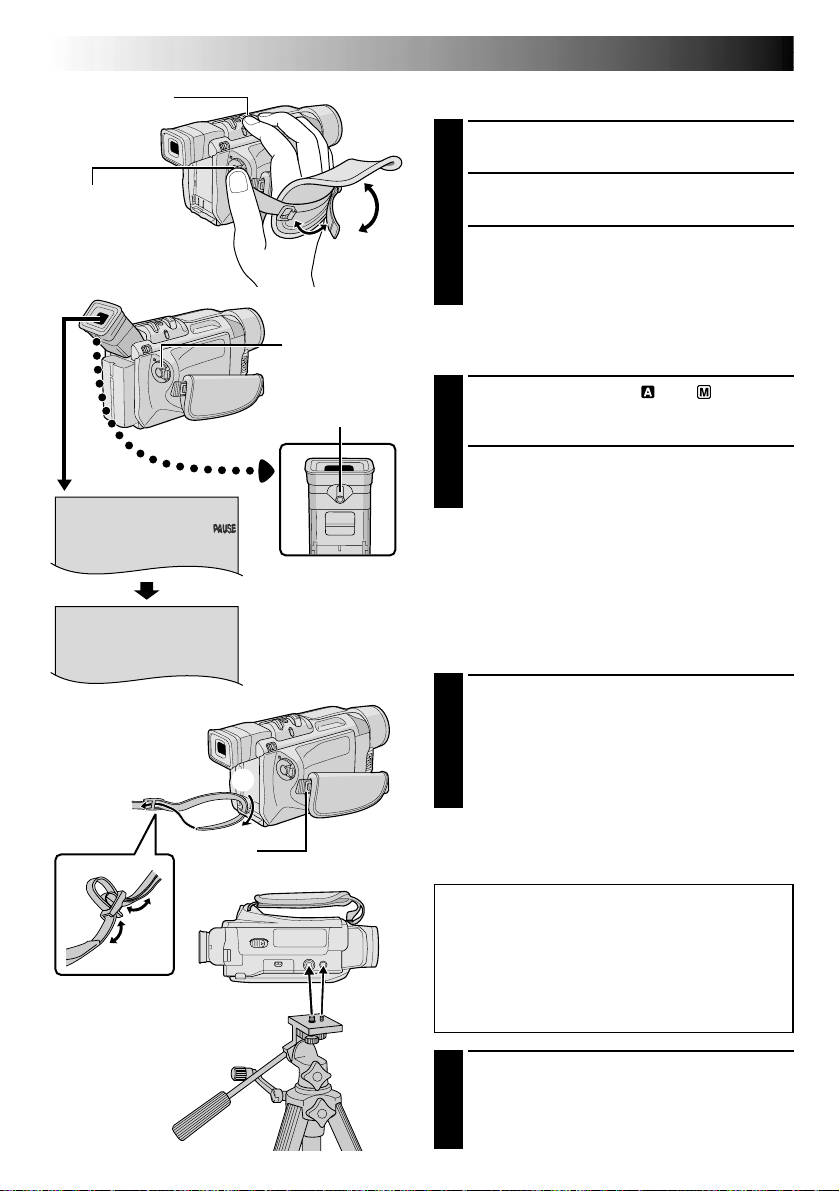
PAUSE
Power Zoom Lever
GETTING STARTED
Grip Adjustment
Separate the Velcro strip.
1
(cont.)
Recording Start/
Stop button
2
Power Switch
Diopter
Adjustment Control
1
Pass your right hand through the loop and grasp
2
the grip.
Adjust your thumb and fingers through the grip,
3
to easily operate the Recording Start/Stop button
and Power Switch and Power Zoom Lever. Be
sure to fasten the Velcro strip to your preference.
Viewfinder Adjustment
Set the Power Switch to “ ” or “ ” while
1
pressing down the Lock Button located on the
switch.
Turn the Diopter Adjustment Control until the
2
indications in the viewfinder are clearly
focused.
Shoulder Strap Attachment
Make sure the battery pack is removed.
1
Following the illustration, thread the strap
through the eyelet 1, then fold it back and
thread it through the buckle 2. Repeat the
procedure to attach the other end of the strap to
the other eyelet 3 located under the Grip Strap .
Confirm the strap is not twisted.
3
Tripod Mounting
CAUTION:
When attaching the camera to a tripod,
extend its legs to stabilize the camcorder. It
is not advised to use small sized tripods.
This may cause damage to the unit by
falling over.
To attach the camera to a tripod, align the
1
direction stud and screw to the mounting socket
and stud hole on the camera. Then tighten the
screw clockwise. Some tripods are not
equipped with studs.
MENU/BRIGHT Wheel
Power Lamp
EN11
Date/Time Settings
The date/time is recorded onto the tape at all times, but its
display can be turned on or off during playback
( pg. 50, 51).
Set the Power Switch to “ ” while pressing down
1
the Lock Button located on the switch. The power
lamp lights and the camcorder is turned on.
Press the MENU/BRIGHT wheel in to access the
2
Menu Screen.
FADER
/ W I P E
AM A EPROGR
AN E
W. BAL
ACAMER
LMANUA
MSYSTE
AYDISPL
DSC
END
T I ME COD E
CLOCK
ADJ .
CLOCK
ADJ .
Power Switch
Display
OF
C
RE NEON SC
–
–
IMETDA TE /
– FFO
NRETUR
Lock Button
F
LCD/ TV
UAOT
25 ’01
CED
30PM:5
25 ’01
CED
30PM:5
GR-DVL915/
DVL815/DVL510
only
DISPLAY Menu
Rotate the MENU/BRIGHT wheel to select
3
“ DISPLAY”. Press it and the DISPLAY Menu
appears.
Rotate the MENU/BRIGHT wheel to select “CLOCK
4
ADJ.”. Press it and “month” is highlighted.
Rotate the MENU/BRIGHT wheel to input the month.
Press it. Repeat to input the day, year, hour and
minute.
Rotate the MENU/BRIGHT wheel to select
“1RETURN”, and press it twice. The Menu Screen
closes.
NOTE:
Even if you select “CLOCK ADJ.”, if the parameter is not
highlighted the camcorder’s internal clock continues to
operate. Once you move the highlight bar to the first date/
time parameter (month), the clock stops. When you finish
setting the minute and press the MENU/BRIGHT wheel in,
the date and time begin operation from the date and time
you just set.
12 EN
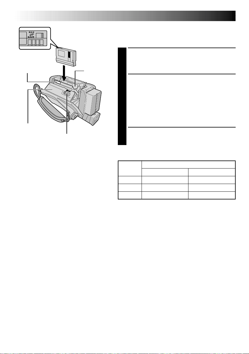
PUSH HERE
Cassette holder
cover
Erase protection tab*
Make sure the
window side is
facing out.
OPEN/EJECT Switch
Cassette
holder
GETTING STARTED
(cont.)
Loading/Unloading A Cassette
The camcorder needs to be powered up to load or eject a
cassette.
Slide and hold OPEN/EJECT in the direction of the
1
arrow then pull the cassette holder cover open until it
locks. The cassette holder opens automatically.
•Do not touch internal components.
Insert or remove a tape and press “PUSH HERE” to
2
close the cassette holder.
•Once the cassette holder is closed, it recedes
automatically. Wait until it recedes completely
before closing the cassette holder cover.
•When the battery’s charge is low, you may not be
able to close the cassette holder cover. Do not
apply force. Replace the battery with a fully charged
one before continuing.
Close the cassette holder cover firmly until it locks
3
into place.
*
To Protect Valuable Recordings . . .
.... slide the erase protection tab on the back of
the tape in the direction of “SAVE”. This
prevents the tape from being recorded over.
To record on this tape, slide the tab back to
“REC” before loading it.
Be sure to press only the section labeled “PUSH
HERE” to close the cassette holder; touching
other parts may cause your finger to get caught
in the cassette holder, resulting in injury or
product damage.
NOTES:
●
It takes a few seconds for the cassette holder to open. Do not apply force.
●
If you wait a few seconds and the cassette holder does not open, close the cassette holder cover and try
again. If the cassette holder still does not open, turn the camcorder off then on again.
●
If the tape does not load properly, open the cassette holder cover fully and remove the cassette. A few
minutes later, insert it again.
●
When the camcorder is suddenly moved from a cold place to a warm environment, wait a short time before
opening the cassette holder cover.
●
Closing the cassette holder cover before the cassette holder comes out may cause damage to the camcorder.
●
Even when the camcorder is switched off, a cassette can be loaded or unloaded. After the cassette holder is
closed with the camcorder switched off, however, it may not recede. It is recommended to turn the power on
before loading or unloading.
●
When resuming recording, once you open the cassette holder cover a blank portion will be recorded on the
tape or a previously recorded scene will be erased (recorded over) regardless of whether the cassette holder
came out or not. See page 20 for information about recording from the middle of a tape.
Approximate recording time
Tape
30 min. 30 min. 45 min.
60 min. 60 min. 90 min.
80 min. 80 min. 120 min.
Recording mode
SP LP
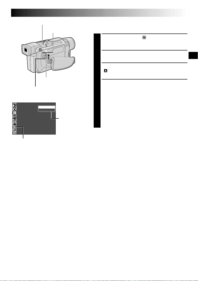
MENU/BRIGHT Wheel
Lock Button
Power Switch
Display
REC MODE – SP
GR-DVL915/DVL815/
DVL510 only
LP
Power Lamp
Menu Screen
Sub Menu
EN13
Recording Mode Setting
Set the tape recording mode depending on your preference.
Set the Power Switch to “ ” while pressing down
1
the Lock Button located on the switch. The power
lamp lights and the camcorder is turned on.
Press the MENU/BRIGHT wheel in. The Menu
2
Screen appears.
Rotate the MENU/BRIGHT wheel to select
3
“ CAMERA” and press it. The CAMERA Menu
appears.
Rotate the MENU/BRIGHT wheel to select “REC
4
MODE” and press it. The Sub Menu appears. Select
“SP” or “LP” by rotating the MENU/BRIGHT wheel
and press it. Rotate the MENU/BRIGHT wheel to
select “1RETURN”, and press it twice. The Menu
Screen closes.
•Audio Dubbing ( pg. 66) and Insert Editing
( pg. 67) are impossible on a tape recorded in the
LP mode.
•“LP” (Long Play) is more economical, providing
1.5 times the recording time.
NOTES:
●
If the recording mode is switched during recording, the
playback picture will be blurred at the switching point.
●
It is recommended that tapes recorded in the LP mode
on this camcorder be played back on this camcorder.
●
During playback of a tape recorded on another
camcorder, blocks of noise may appear or there may be
momentary pauses in the sound.
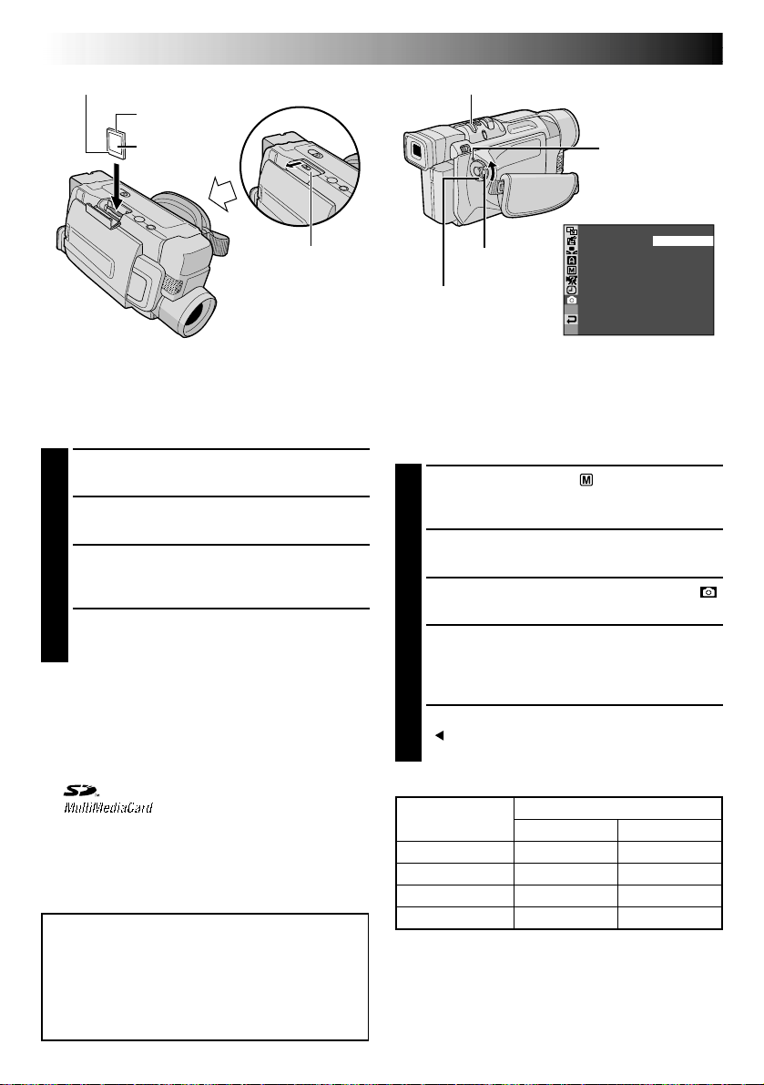
14 EN
Clipped edge
Memory card
GETTING STARTED
MENU/BRIGHT Wheel
(cont.)
Label
Card Cover
Loading A Memory Card
(GR-DVL915/DVL815/DVL510 only)
The provided MultiMediaCard is already inserted in
the camcorder when you receive the camcorder.
Make sure the camcorder’s power is off.
1
Open the card cover (MEMORY CARD).
2
Insert the memory card clipped edge first.
3
•Do not touch the terminal on the reverse side
of the label.
To close the card cover, push it until you hear a
4
click.
To Unload A Memory Card . . .
.... in step 3 push the memory card, which then
comes out of the camcorder automatically. Pull it
out and close the card cover.
NOTES:
●
Be sure to use only SD Memory Cards marked
“ ” or MultiMediaCards marked
“ ”.
●
Some brands of memory cards are not compatible
with this camcorder. Before purchasing a memory
card , consult its manufacturer or dealer.
●
Before using a new memory card, it is necessary to
FORMAT the card. pg. 36.
ATTENTION:
Do not insert/remove the memory card while the
camcorder is turned on, as this may cause the
memory card to be corrupted or cause the
camcorder to become unable to recognize
whether or not the card is installed.
Power Lamp
Display
– FINE
TYQUAL I
Lock Button
Power Switch
SIZE
UXGA
ST ANDARD–
GAV
–
AUTO
–
NRETUR
Picture Quality Mode Setting
(GR-DVL915/DVL815/DVL510 only)
The Picture Quality mode can be selected to best
match your needs. Two Picture Quality modes are
available: FINE and STANDARD (in order of quality).
Set the Power Switch to “ ” while pressing
1
down the Lock Button located on the switch. The
power lamp lights and the camcorder turns on.
Press the MENU/BRIGHT wheel in. The Menu
2
Screen appears.
Rotate the MENU/BRIGHT wheel to select “
3
DSC” and press it. The DSC Menu appears.
Rotate the MENU/BRIGHT wheel to select
4
“QUALITY” and press it. The Sub Menu
appears. Rotate the MENU/BRIGHT wheel to
select the desired mode and press it.
Rotate the MENU/BRIGHT wheel to select
5
“ RETURN”, and press it twice. The Menu
Screen closes.
Approximate Number of Storable Images
Memory Card
8 MB**
16 MB*
32 MB (optional)
64 MB (optional)
* Provided with GR-DVL915/DVL815 only.
** Provided with GR-DVL510 only.
NOTE:
The number of storable images depends on the
selected picture quality as well as the composition of
the subjects in the images and the type of memory
card being used.
Picture Quality Mode
FINE
100
200
400
800
STANDARD
200
400
800
1600

VIDEO RECORDING & PLAYBACK
VIDEO RECORDING
VIDEO RECORDING ....................... 16 – 20
Basic Recording ...................................... 16
Journalistic Shooting ................................ 17
Self-Recording ....................................... 17
Operation Mode ..................................... 17
Zooming ............................................. 18
Video Light .......................................... 19
Time Code ............................................ 20
VIDEO PLAYBACK ......................... 21 – 24
Normal Playback .................................... 21
Still Playback ........................................ 21
Shuttle Search ....................................... 21
Frame-By-Frame Playback ......................... 21
Connections ................................... 22 – 23
Blank Search ......................................... 24
EN15
&
PLAYBACK
CONTENTS
16 EN
25
min
BR I GHT
Power lamp
Power Switch
Lock Button
Recording Start/Stop Button
Display
min
(Now calculating)
90 min
(Blinking) (Blinking) (Blinking)
Tape remaining
time indicator
(Approximate)
89 min
1 min0 min
During
shooting
3 min
2 min
VIDEO RECORDING
Basic Recording
NOTE:
You should already have performed the procedures listed
below. If not, do so before continuing.
●
Power ( pg. 8)
●
Grip Adjustment ( pg. 10)
●
Viewfinder Adjustment ( pg. 10)
●
Load A Cassette ( pg. 12)
●
Recording Mode Setting ( pg. 13)
Press in the tabs on the lens cap to remove it.
1
GR-DVL915/DVL815/DVL510 only:
OPEN, open the LCD monitor and set the VIDEO/
DSC Switch to “VIDEO”.
Set the Power Switch to “ ” or “ ” while pressing
2
down the Lock Button located on the switch.
Shooting while using the LCD monitor:
the LCD monitor is fully open. Tilt it upward/
downward for best viewability.
Shooting while using the viewfinder:
monitor.
•The power lamp lights and the camcorder enters the
Record-Standby mode. “PAUSE” is displayed.
Press the Recording Start/Stop Button. “ ”
3
appears while recording is in progress.
Press PUSH
Make sure
Close the LCD
180°
PUSH-OPEN
Button
MENU/BRIGHT Wheel
90°
VIDEO/DSC Switch
(GR-DVL915/DVL815/
DVL510 only)
Tally lamp (lights while
recording is in progress)
To Stop Recording . . .
.... press the Recording Start/Stop Button. The camcorder
re-enters the Record-Standby mode.
To Adjust The Brightness Of The Display
.... rotate the MENU/BRIGHT wheel until the bright level
indicator on the display moves and the appropriate
brightness is reached.
•If you are using the GR-DVL915/DVL815, it is also
possible to adjust the brightness of the viewfinder by
closing the LCD monitor and adjusting as described
above.
NOTES:
●
If the Record-Standby mode continues for 5 minutes, the
camcorder’s power shuts off automatically. To turn the
camcorder on again, set the Power Switch to “OFF”,
then back to “ ” or “ ”.
●
The image will not appear simultaneously on the LCD
monitor and the viewfinder. It will appear in the
viewfinder when the LCD monitor is in the lock
position, and it will appear on the LCD monitor when
fully extended.
●
When a blank portion is left between recorded scenes
on the tape, the time code is interrupted and errors may
occur when editing the tape. To avoid this, refer to
“Recording from the middle of a tape” ( pg. 20).
●
To turn the tally lamp or beep sounds off, pg. 46, 48.
For other notes, pg. 71
Self-Recording
EN17
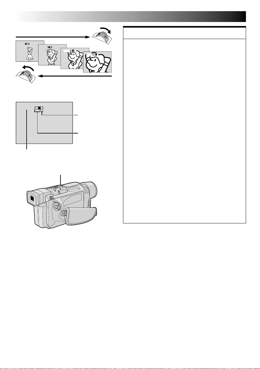
JOURNALISTIC SHOOTING
In some situations, different shooting angles may
provide more dramatic results. Hold the camcorder in
the desired position and tilt the LCD monitor in the most
convenient direction. It can rotate 270° (90° downward,
180° upward).
SELF-RECORDING
You can shoot yourself while viewing your own image
in the LCD monitor. Open the LCD monitor and tilt it
upward 180° so that it faces forward, then point the lens
toward yourself and start recording.
To turn on the camcorder, set the Power Switch
to any operation mode except “OFF”while
pressing down the Lock Button located on the
switch.
Power Switch
Power lamp
VIDEO/DSC Switch (GR-DVL915/
DVL815/DVL510 only; open the
LCD monitor to access this switch.)
When the Power Switch is set to “ ”, “ ”
appears. When set to “
indication.
(GR-DVL915/DVL815/DVL510 only)
When the Power Switch is set to “ ” or “ ” and
the VIDEO/DSC Switch is set to “
appears. When set to “VIDEO”, there is no
indication.
” or “ ”, there is no
F
F
O
Y
A
L
P
Lock Button
”, “ ”
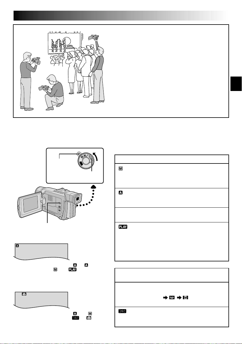
Operation Mode
Choose the appropriate operation mode according to your
preference using the Power Switch and VIDEO/DSC
Switch (GR-DVL915/DVL815/DVL510 only).
Power Switch Position
(Manual):
Allows you to set various recording functions using the
Menus. If you want more creative capabilities than Full
Auto recording, try this mode.
(Full Auto):
Allows you to record using NO special effects or manual
adjustments. Suitable for standard recording.
OFF:
Allows you to switch off the camcorder.
:
• Allows you to play back a recording on the tape.
• Allows you to transfer a still image recorded on the tape
to a computer (GR-DVL310 only).
• Allows you to display a still image stored in the memory
card or to transfer a still image stored in the memory card
to a computer (GR-DVL915/DVL815/DVL510 only).
VIDEO/DSC Switch Position
(GR-DVL915/DVL815/DVL510 only)
VIDEO:
Allows you to record on a tape or play back a tape. If
“REC SELECT” is set to
Screen, still images are also recorded in the memory card.
:
Allows you to record a still image or display a still image
stored in the memory card.
“ / ”
in the DSC Menu
18 EN
1xW
T
10xW
T
20xW
T
40xW
T
VIDEO RECORDING
(cont.)
Zoom in (T: Telephoto)
Zoom display
10xW
Approximate zoom ratio
T
Power Zoom Lever
Zoom out (W: Wide angle)
Digital zoom zone
10X (optical)
zoom zone
FEATURE:
Zooming
PURPOSE:
To produce the zoom in/out effect, or an instantaneous
change in image magnification.
OPERATION:
Zoom In
Slide the Power Zoom Lever towards “T”.
Zoom Out
Slide the Power Zoom Lever towards “W”.
The further you slide the Power Zoom Lever, the
quicker the zoom action.
NOTES:
●
Focusing may become unstable during Zooming. In
this case, set the zoom while in Record-Standby,
lock the focus by using the manual focus
( pg. 43), then zoom in or out in Record mode.
●
Zooming is possible to a maximum of 400X, or it
can be switched to 10X magnification using the
optical zoom ( pg. 47).
●
Zoom magnification of over 10X is done through
Digital image processing, and is therefore called
Digital Zoom.
●
During Digital zoom, the quality of image may
suffer.
●
Digital zoom cannot be used when digital image
processing, such as Picture Wipe/Dissolve
( pg. 40, 41) or Video Echo ( pg. 39), is
activated.
●
Macro shooting (as close as approx. 5 cm (2") to the
subject) is possible when the Power Zoom Lever is
set all the way to “W”. Also see “TELE MACRO” in
the Menu Screen on page 48.
EN19
LIGHT OFF/AUTO/ON Switch
(Open the LCD monitor to
access this switch.)
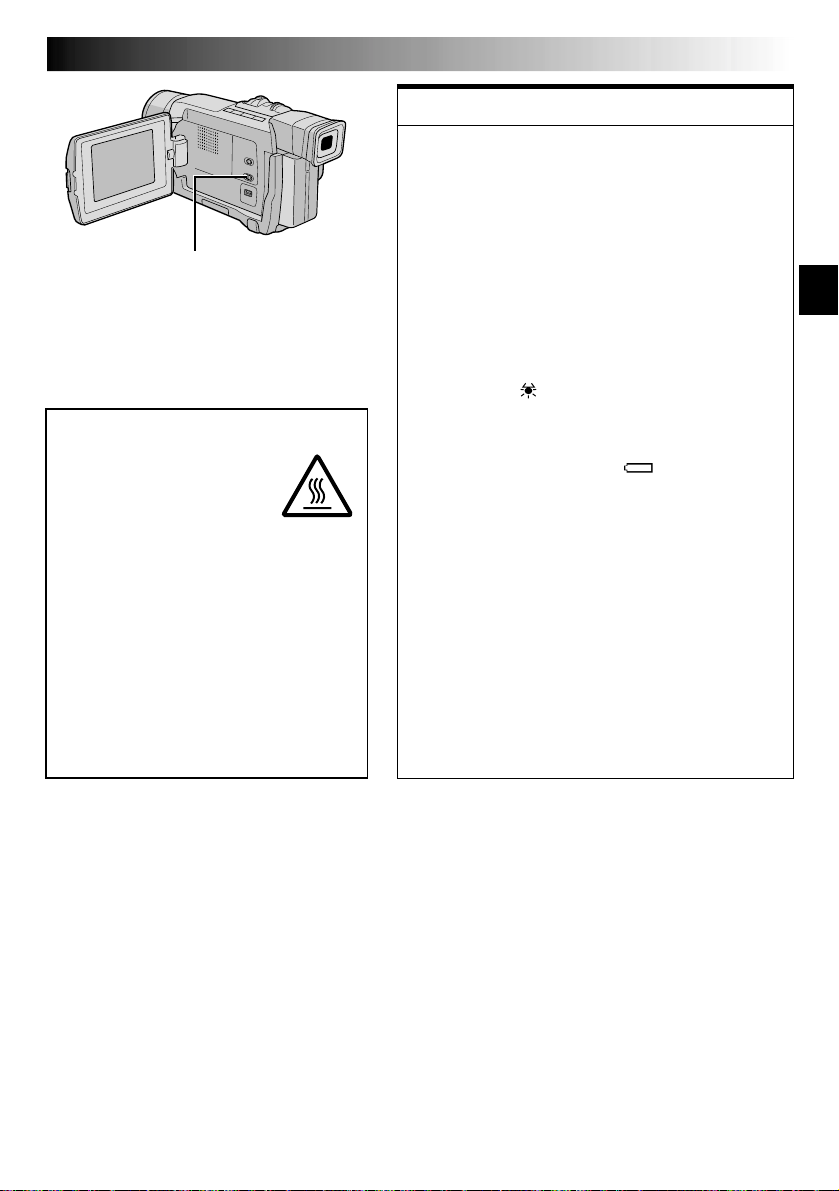
DANGER
The video light can become
extremely hot. Do not touch
it either while in operation or
soon after turning it off,
otherwise serious injury may
result.
Do not place the camcorder into the
carrying case immediately after using the
video light, since it remains extremely
hot for some time.
When operating, keep a distance of
about 30 cm (11-13/16") between the
video light and people or objects.
Do not use near flammable or explosive
materials.
It is recommended that you consult your
nearest JVC dealer for replacing the video
light.
FEATURE:
Video Light
PURPOSE:
To brighten the scene when natural lighting is too dim.
OPERATION:
Set LIGHT OFF/AUTO/ON as required:
OFF : Turns off the light.
AUTO : Automatically turns on the light when the
ON : Always keeps the light on as long as the
The video light can only be used with the
It is recommended to set the white balance
When not using the video light, turn it off to save
NOTES:
●
●
camcorder senses insufficient lighting on the
subject.
camcorder is turned on.
camcorder’s power on.
( pg. 45) to when you use the video light.
battery power.
Even if the battery indicator
( )
does not blink
due to low battery charge, the camcorder may turn
off automatically when you turn on the video light,
or when you start recording with the video light
turned on.
When LIGHT OFF/AUTO/ON is set to “AUTO”:
•
Depending on the lighting conditions, the video
light may keep turning on and off. In this case,
manually switch the light on or off using LIGHT
OFF/AUTO/ON.
•
While the “SHUTTER” or “SPORTS” mode
( pg. 39) is engaged, the light is likely to stay
on.
•
While the “TWILIGHT” mode ( pg. 39) is
engaged, the light will not activate.
•
While the “Night-Alive” mode ( pg. 38) is
engaged, the light will not activate.
20 EN
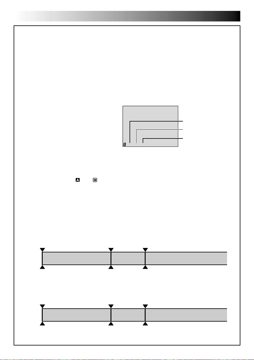
VIDEO RECORDING
Time Code
During recording, a time code is recorded on the tape. This code is to confirm the location of the recorded
scene on the tape during playback.
If recording starts from a blank portion, the time code begins counting from “00:00:00”
(minute:second:frame). If recording starts from the end of a previously recorded scene, the time code
continues from the last time code number.
To perform Random Assemble Editing ( pg. 61 – 65), time code is necessary. If during recording a blank
portion is left partway through the tape, the time code is interrupted. When recording is resumed, the time
code starts counting up again from “00:00:00”. This means the camcorder may record the same time
codes as those existing in a previously recorded scene. To prevent this, perform “Recording From The
Middle of A Tape” below in the following cases;
•When shooting again after playing back a
recorded tape.
•When power shuts off during shooting.
•When a tape is removed and re-inserted during
shooting.
•When shooting using a partially recorded tape.
•When shooting on a blank portion located
partway through the tape.
•When shooting again after shooting a scene
then opening/closing the cassette holder cover.
Recording From The Middle Of A Tape
1. Play back a tape or use Blank Search ( pg. 24) to find the spot at which you want to start recording,
then engage the Still Playback mode ( pg. 21).
2. Set the Power Switch to “ ” or “ ” while pressing down the Lock Button located on the switch, then
start recording.
NOTES:
●
The time code cannot be reset.
●
During fast-forwarding and rewinding, the time code indication does not move smoothly.
●
The time code is displayed only when “TIME CODE” is set to “ON” ( pg. 49, 50).
12:34:24
Display
Frames are not displayed
during recording.
Minutes
Seconds
Frames
(30 frames = 1 second)
(cont.)
When a blank portion is recorded on a tape
Time code
00:00:00
Tape
Shooting start point
Time code
05:43:21
Proper recording
Time code
00:00:00
Tape
Shooting start point
Time code
05:43:21
Time code
00:00:00
Shooting start pointShooting stop point
Time code
05:44:00
Shooting start pointShooting start point
Newly recorded sceneBlankAlready recorded scene
Latest sceneNew sceneAlready recorded scene
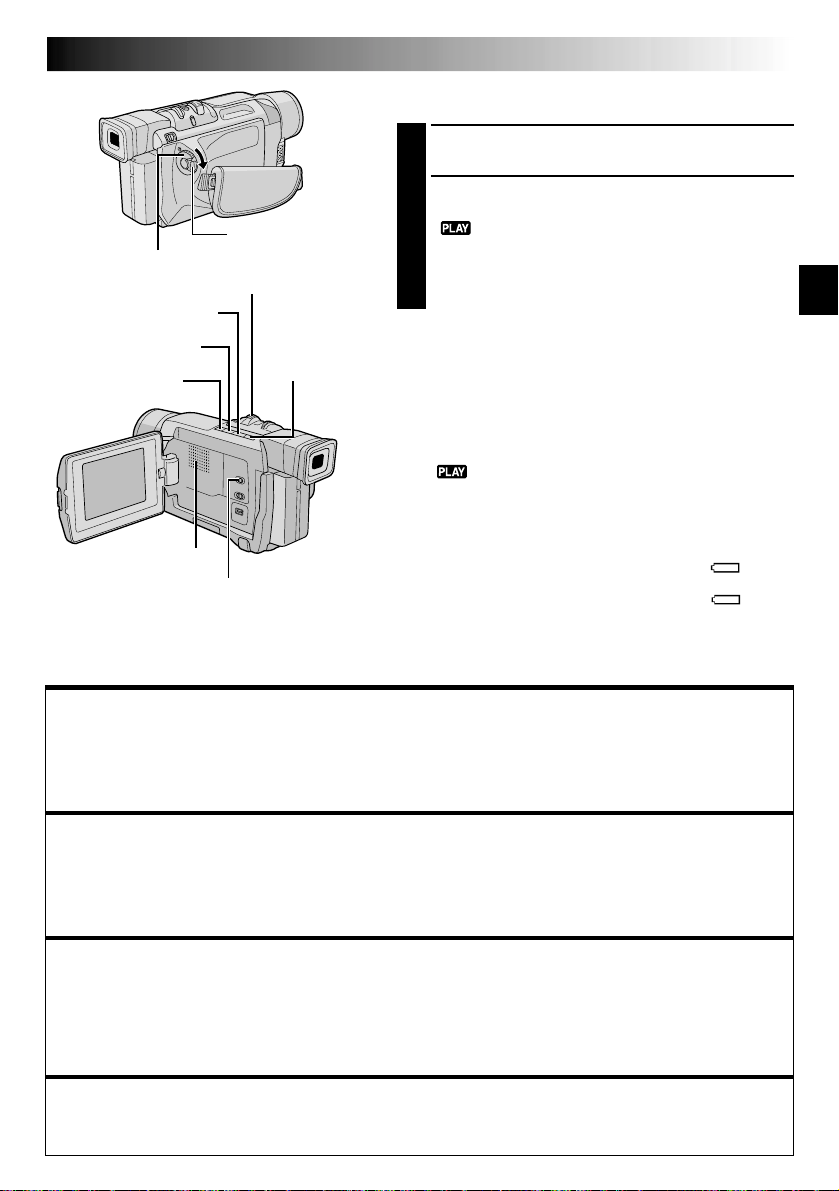
VIDEO PLAYBACK
Lock Button
Power Switch
Power Zoom Lever (VOL.)
Play/Pause Button (
Rewind Button (
Stop Button (5)
4
/6)
2
)
Speaker
VIDEO/DSC Switch (GR-DVL915/
DVL815/DVL510 only; open the
LCD monitor to access this switch)
Fast-Forward
Button (
3
Normal Playback
Load a tape ( pg. 12).
1
Set the VIDEO/DSC Switch to “VIDEO” (GR-DVL915/
2
DVL815/DVL510 only), then set the Power Switch to
“ ” while pressing down the Lock Button located
on the switch. To start playback, press 4/6.
•To stop playback, press 5.
•Press 2 to rewind, or 3 to fast-forward the tape
during Stop mode.
To Control The Speaker Volume . . .
.... slide the Power Zoom Lever (VOL.) towards “+” to
)
turn up the volume, or towards “–” to turn down the
volume.
NOTES:
●
If Stop mode continues for 5 minutes when power is
supplied from a battery, the camcorder shuts off automatically. To turn on again, set the Power Switch to “OFF”, then
to “ ”.
●
The playback picture can be viewed in the LCD monitor,
viewfinder or on a connected TV ( pg. 22).
●
You can also view the playback picture on the LCD monitor
with it flipped over and pushed against the camera body.
●
LCD monitor/viewfinder indications:
•
When power is supplied from a battery: the “ ”
battery pack remaining power indicator is displayed.
When power is supplied from an AC outlet: “ ” does
not appear.
•
During Stop mode, none of the indications are displayed.
●
When a cable is connected to the AV connector, the sound
is not heard from the speaker.
EN21
Still Playback:
1) Press 4/6 during playback.
2) To resume normal playback, press 4/6 again.
●
If still playback continues for more than about 3 minutes, the camcorder’s Stop mode is automatically
engaged. After 5 minutes in the Stop mode, the camcorder’s power is automatically turned off.
●
When
4
/6
Shuttle Search:
1) Press 3 for forward or 2 for reverse search during playback.
2) To resume normal playback, press 4/6.
●
During playback, press and hold 2 or 3. The search continues as long as you hold the button. Once you
release it, normal playback resumes.
●
A slight mosaic effect appears on screen during Shuttle Search. This is not a malfunction.
Pauses during playback.
is pressed, the image may not pause immediately while the camcorder stabilizes the still image.
Allows high-speed search in either direction.
Frame-By-Frame Playback: Allows frame-by-frame search.
1) Engage Still Playback.
2) Rotate the MENU/BRIGHT wheel towards “+” for forward Frame-By-Frame Playback, or towards “–” for reverse
Frame-By-Frame Playback during Still Playback.
To resume normal playback, press 4/6.
●
If you are using the GR-DVL915/DVL815, you can also use the provided remote control for Frame-By-Frame
Playback ( pg. 59).
Slow-Motion Playback/Playback Special Effects (GR-DVL915/DVL815 only)
and Playback Zoom
Available only with the remote control (provided) ( pg. 59, 60).
22 EN
VIDEO PLAYBACK
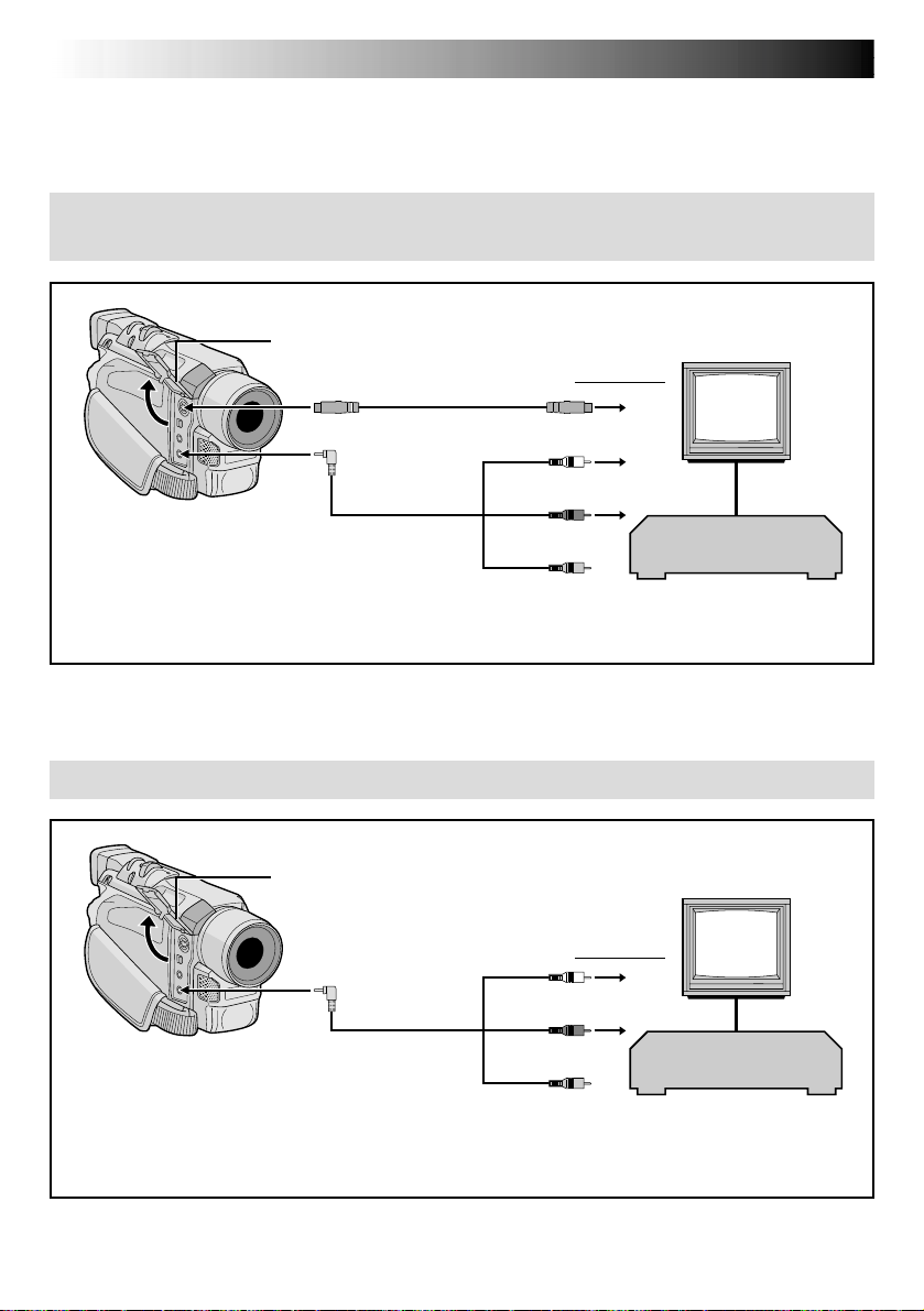
Connections
These are some basic types of connections. When making the connections, refer also to your VCR and TV
instruction manuals.
A.Connection to a TV or VCR equipped with an S-VIDEO IN and A/V input
connectors
Connector cover*
To S
S-Video cable
(optional)
To TV or VCR
TV
To S-VIDEO IN
(cont.)
To AV
NOTE:
In order to maintain optimum performance of
the camcorder, provided cables may be
equipped with one or more core filter. If a cable
has only one core filter, the end that is closest to
the filter should be connected to the camcorder.
* When connecting the cables, open this cover.
** The Audio cable is not required for watching still images only.
Audio/Video cable
(provided)
White to
AUDIO L IN**
Red to
AUDIO R IN**
Yellow:
Not connected
VCR
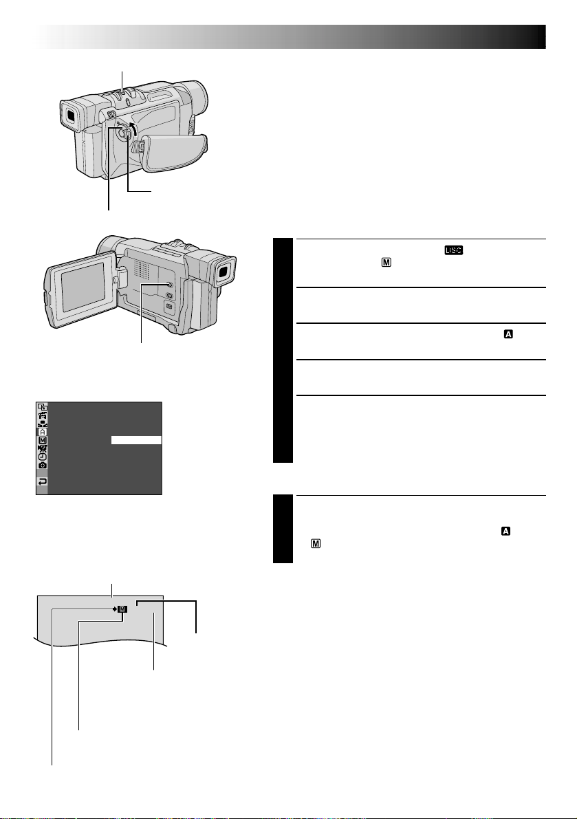
B. Connection to a TV or VCR equipped only with A/V input connectors
Connector cover*
TV
VCR
To AV
NOTE:
In order to maintain optimum performance of
the camcorder, provided cables may be
equipped with one or more core filter. If a cable
has only one core filter, the end that is closest to
the filter should be connected to the camcorder.
Audio/Video cable
(provided)
To TV or VCR
White to
AUDIO L IN**
Red to
AUDIO R IN**
Yellow to
VIDEO IN
* When connecting the cables, open this cover.
** The Audio cable is not required for watching still images only.

Make sure all units are turned off.
1
Connect the camcorder to a TV or VCR as
2
shown in the illustration ( pg. 22).
If using a VCR . . . go to step 3.
If not . . . go to step 4.
Connect the VCR output to the TV input,
3
referring to your VCR’s instruction manual.
Turn on the camcorder, the VCR and the TV.
4
Set the VCR to its AUX input mode, and set the
5
TV to its VIDEO mode.
To choose whether or not the following displays
appear on the connected TV . . .
•Date/Time
.... set “DATE/TIME” to “AUTO”, “ON” or “OFF”
in the Menu Screen ( pg. 50).
•Time Code
.... set “TIME CODE” to “ON” or “OFF” in the
Menu Screen ( pg. 50).
•Playback Sound Mode, Tape Speed And Tape
Running Displays for video playback
Or
Directory/File Names and Image Number/Total
Number of Images for D.S.C. Playback
(GR-DVL915/DVL815/DVL510 only)
.... set “ON SCREEN” to “LCD” or “LCD/TV” in
the Menu Screen ( pg. 50).
Or, press DISPLAY on the remote control
(provided with GR-DVL915/DVL815 only).
EN23
NOTES:
●
It is recommended to use the AC Adapter as the
power supply instead of the battery pack
( pg. 9).
●
The S-Video cable is optional. Be sure to use the
YTU94146A S-Video cable.
Consult the JVC Service Center described on the
sheet included in the package for details on its
availability. Make sure to connect the end with a
core filter to the camcorder. The core filter
reduces interference.
●
To monitor the picture and sound from the
camcorder without inserting a tape or memory
card*, set the camcorder’s Power Switch to “ ” or
“ ”, then set your TV to the appropriate input
mode.
*
GR-DVL915/DVL815/DVL510 only
●
Make sure you adjust the TV sound volume to its
minimum level to avoid a sudden burst of sound
when the camcorder is turned on.
●
If you have a TV or speakers that are not specially
shielded, do not place the speakers adjacent to the
TV as interference will occur in the camcorder
playback picture.
●
If no image is displayed or no sound is heard from
the TV, set “S/AV INPUT” to “OFF” in the Menu
Screen (GR-DVL915 only, pg. 50).

24 EN
BLANK SEARCH Button
Power Switch
Display
Lock Button
44
VIDEO PLAYBACK
(cont.)
Blank Search
Helps you find where you should start recording in the
middle of a tape to avoid time code interruption ( pg. 20).
Load a tape ( pg. 12).
1
Set the VIDEO/DSC Switch to “VIDEO” (GR-DVL915/
2
DVL815/DVL510 only), then set the Power Switch to
“ ” while pressing down the Lock Button located
on the switch.
Press BLANK SEARCH.
3
•“BLANK SEARCH” appears blinking and the
camcorder automatically starts reverse or forward
shuttle search, then stops at the spot which is about
3 seconds of tape before the beginning of the
detected blank portion.
BLANK SEARCH
Stop Button (5)
VIDEO/DSC Switch (GR-DVL915/
DVL815/DVL510 only; open the
LCD monitor to access this switch)
To cancel Blank Search midway . . .
.... press 5.
NOTES:
●
In step 3, if the current position is at a blank portion the
camcorder searches in the reverse direction, and if the
current position is at a recorded portion the camcorder
searches in the forward direction.
●
Blank Search does not work if “HEAD CLEANING
REQUIRED. USE CLEANING CASSETTE” has appeared
with the tape.
●
If the beginning or end of the tape is reached during
Blank Search, the camcorder stops automatically.
●
A blank portion which is shorter than 5 seconds of tape
may not be detected.
●
The detected blank portion may be located between
recorded scenes. Before you start recording, make sure
there is no recorded scene after the blank portion.

DIGITAL STILL CAMERA (D.S.C.) RECORDING & PLAYBACK
DIGITAL STILL CAMERA
(D.S.C.) RECORDING
&
PLAYBACK
The D.S.C. (Digital Still Camera) features
are available on GR-DVL915, GR-DVL815
and GR-DVL510.
CONTENTS
D.S.C. RECORDING ....................... 26 – 27
Basic Shooting (Snapshot) ................... 26 – 27
D.S.C. PLAYBACK ......................... 28 – 36
Normal Playback .................................... 28
Auto Playback ....................................... 28
INDEX Screen ........................................ 29
EN25
Index Playback ...................................... 29
Jump Playback ...................................... 30
Protecting Images ................................... 31
Deleting Images ............................. 32 – 33
Setting Print Information
(DPOF Setting) .............................. 34 – 35
Initializing A Memory Card ......................... 36
26 EN
FINE
10 /100
VIDEO/DSC Switch (Open the
LCD monitor to access this switch.)
SNAP MODE –
SNAPSHOT Button
Power Switch
Display
PIN– UP
FRAME
FULL
MUL T I –
MUL T I –
Lock Button
Menu Screen
4
9
D.S.C. RECORDING
Basic Shooting (Snapshot)
You can use your camcorder as a Digital Still Camera for
taking snapshots.
NOTE:
You should already have performed the procedures listed
below. If not, do so before continuing.
●
Power ( pg. 8)
●
Grip Adjustment ( pg. 10)
●
Viewfinder Adjustment ( pg. 10)
●
Loading A Memory Card ( pg. 14)
●
Picture Quality Mode Setting ( pg. 14)
SNAPSHOT MODE SELECTION
Set the VIDEO/DSC Switch to “ ”, then set the
1
Power Switch to “ ” while pressing down the Lock
Button located on the switch.
Press the MENU/BRIGHT wheel in. The Menu
2
Screen appears.
Rotate the MENU/BRIGHT wheel to select “
3
CAMERA”. Press it and the CAMERA Menu appears.
Rotate the MENU/BRIGHT wheel to select “SNAP
4
MODE”, then press it.
Rotate the MENU/BRIGHT wheel to select the
5
desired Snapshot mode, then press it.
Rotate the MENU/BRIGHT wheel to select
“1RETURN” and press it twice. The Menu Screen
closes.
SNAPSHOT RECORDING
1
Picture Quality
Displays the quality of the stored image: FINE or STD
(standard) (in order of quality) (
Total number of shots
Displays the approximate total number of shots that can be stored, including those already taken.
The number increases or decreases depending on the shots stored, the Picture Quality mode, etc.
Card icon
Appears during shooting and blinks when a memory card is not loaded.
Shooting icon
Appears and blinks during shooting.
pg. 14).
Number of shots taken
Displays the number of images that have already been shot.
Press SNAPSHOT.
The image is recorded in the memory card.
•Regardless of the Power Switch position (“ ” or
“ ”), Snapshot recording takes place using the
selected Snapshot mode.
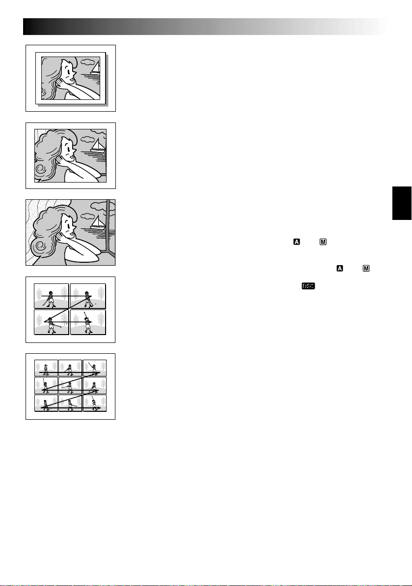
PIN-UP
Pin-Up mode*
FRAME
Snapshot mode
with frame*
FULL
Snapshot mode
with no frame*
MULTI-4
Multi-Analyzer 4
EN27
To Delete Unwanted Still Images . . .
.... when unwanted still images are stored in the memory
card or its memory is full, refer to “Deleting Images”
( pg. 32) and delete unwanted still images.
To Remove The Shutter Sound . . .
.... when you do not want to hear the shutter sound, set
“BEEP” to “OFF” in the Menu Screen ( pg. 46, 48).
The sound is no longer heard from the speaker.
NOTES:
●
Even if “MULTI-4” or “MULTI-9” is engaged, Snapshot
recording will be performed in the FULL mode during
Digital Zoom or Night-Alive ( pg. 38).
●
Even if “DIS” is set to “ON” ( pg. 47), the Stabilizer
will be disabled.
●
If Snapshot recording is not possible, “PHOTO” blinks
when SNAPSHOT is pressed.
●
If Program AE with special effects ( pg. 38) is
engaged, certain modes of Program AE with special
effects are disabled during Snapshot recording. In such a
case, the icon blinks.
●
If shooting is not performed for approx. 5 minutes when
the Power Switch is set to “ ” or “ ” and power is
supplied from the battery pack, the camcorder shuts off
automatically to save power. To perform shooting again,
set the Power Switch to “OFF”, then to “ ” or “ ”.
●
The Motor Drive mode ( pg. 42) is disabled when the
VIDEO/DSC Switch is set to “ ”.
●
Still images taken are compliant to DCF (Design rules for
Camera File systems). They do not have any compatibility with devices which are not compliant to DCF.
MULTI-9
Multi-Analyzer 9
* There is the sound effect of a shutter closing.
28 EN
JAN
JAN
JAN
JAN
Fast-Forward (3)
Button
Play (
4
/6) Button
Rewind (
2
)
Display
J
JAN
10 ’01
Button
Stop (5) Button
VIDEO/DSC Switch (Open the
LCD monitor to access this switch.)
[For Normal Playback]
To display the next image
Lock Button
F
F
O
Y
A
L
P
Power Switch
[For Auto Playback]
-
0010
100
10 / 24
-
0011
100
/
24
11
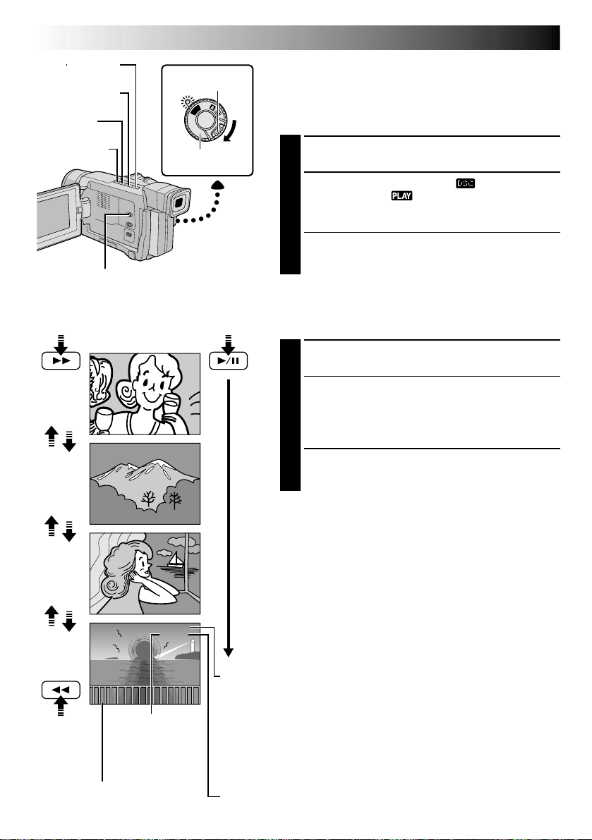
D.S.C. PLAYBACK
Normal Playback
Images shot with the camcorder are automatically
numbered, then stored in numerical order in the memory
card. You can view the stored images, one at a time, much
like flipping through a photo album.
Load a memory card ( pg. 14).
1
Set the VIDEO/DSC Switch to “ ”, then set the
Power Switch to “ ” while pressing down the
2
Lock Button.
•A stored image is displayed.
Press 3 to display the next image.
Press 2 to display the previous image.
3
Auto Playback
You can run through all the images stored in memory
automatically.
Perform steps 1 and 2 above.
1
Press 4/6.
•If you press 2 during Auto Playback, images are
2
displayed in descending order.
•If you press 3during Auto Playback, images are
displayed in ascending order.
To end Auto Playback, press 5.
3
JAN
10 ’01
-
0012
100
/
24
JAN
10 ’01
JAN
10 ’01
To display the
previous image
Date
Displays the date when the image was
shot (if “DATE/TIME” is set to “ON” in
the Menu Screen
Image number
Displays the index
number of the image
file (
pg. 50 – 51).
12
100
13
pg. 29).
-
0013
/
24
NOTES:
●
Even if you shoot a new image after playing back a lownumbered one, this will not overwrite an existing image,
because new images are automatically stored after the
last-recorded one.
●
Images shot in a file size other than VGA with devices
that are compatible with DCF (Design rules for Camera
File systems) will be displayed as reduced-size thumbnail images. These thumbnail images cannot be
transferred to a PC.
●
Images shot with devices that are not compatible with
DCF cannot be viewed with this camcorder; “Unsupported Data!” will be displayed.
Directory and File names
Displays the directory and file names.
Shows that the selected shot is in a directory called “100” and its file name is
“DVC00013”.
Each time shooting takes place, a file name is made using a number which is
larger by one than the largest number of the file names which are in use. If the
file name reaches DVC09999, a new directory will be made and the file name
will start again from DVC00001.
In the playback screen, the directory and only the last four digits of the file name
are displayed.
Total number of images
Displays the total number of stored images.
Loading...