


 Loading...
Icom IC-F4036T, IC-F4036S, IC-F4033S, IC-F4031S, IC-F4031T User Manual
...INSTRUCTION MANUAL
VHF TRANSCEIVERS
iF3030Series
UHF TRANSCEIVERS
iF4030Series
This device complies with Part 15 of the FCC Rules. Operation is subject to the condition that this device does not cause harmful interference.
The photo shows the
VHF transceiver

FOREWORD
Thank you for choosing this Icom product. This product is designed and built with Icom’s state of the art technology and craftsmanship. With proper care this product should provide you with years of trouble-free operation.
IMPORTANT
READ ALL INSTRUCTIONS carefully and completely before using the transceiver.
SAVE THIS INSTRUCTION MANUAL — This instruction manual contains important operating instructions for the IC-F3031S, IC-
F3031T, IC-F3033S, IC-F3033T, IC-F3033T-T, IC-F3036S, ICF3036T VHF TRANSCEIVERS and the IC-F4031S, IC-F4031T, ICF4033S, IC-F4033T, IC-F4036S, IC-F4036T UHF TRANSCEIVERS.
This instruction manual includes some functions which are usable only when they are preset by your dealer. Ask your dealer for details.
EXPLICIT DEFINITIONS
WORD |
DEFINITION |
|
RDANGER! |
Personal death, serious injury or an explosion |
|
may occur. |
||
|
||
RWARNING! |
Personal injury, fire hazard or electric shock |
|
may occur. |
||
|
||
CAUTION |
Equipment damage may occur. |
|
NOTE |
If disregarded, inconvenience only. No risk of |
|
personal injury, fire or electric shock. |
||
|
RECOMMENDATION
CLEAN THE TRANSCEIVER THOROUGHLY WITH FRESH WATER after exposure to saltwater, and dry it before operating. Otherwise, the transceiver’s keys, switches and controllers may become unusable, due to salt crystallization, and/or the charging terminals of the battery pack may rust.
NOTE: If the transceiver’s waterproof protection appears defective, carefully clean it with a soft, wet (fresh water) cloth, then, dry it before operating. The transceiver may lose its waterproof protection if the case or jack cover is cracked or broken, or the transceiver has been dropped.
Icom, Icom Inc. and Icom logo are registered trademarks of Icom Incorporated (Japan) in Japan, the United States, the United Kingdom, Germany, France, Spain, Russia, Australia, New Zealand, and/or other countries.
i

PRECAUTIONS
R DANGER! NEVER short terminals of the battery pack. Also, current may flow into nearby metal objects such as a key, so be careful when placing the battery packs (or the transceiver) in handbags, and so on. Simply carrying with or placing near metal objects such as a key, and so on may cause shorting. This may damage not only the battery pack, but also the transceiver.
R DANGER! Use and charge only specified Icom battery packs with Icom transceivers or Icom chargers. Only Icom battery packs are tested and approved for use with Icom transceivers or charged with Icom chargers. Using third-party or counterfeit battery packs or chargers may cause smoke, fire, or cause the battery to burst.
R WARNING! NEVER hold the transceiver so that the antenna is very close to, or touching exposed parts of the body, especially the face or eyes, while transmitting. The transceiver will perform best if the microphone is 5 to 10 cm (2 to 4 inches) away from the lips and the transceiver is vertical.
R WARNING! NEVER operate the transceiver with a headset or other audio accessories at high volume levels. The continuous high volume operation may cause a ringing in your ears. If you experience the ringing, reduce the volume level or discontinue use.
R WARNING! NEVER operate the transceiver while driving a vehicle. Safe driving requires your full attention— anything less may result in an accident.
CAUTION: MAKE SURE the flexible antenna, battery pack and jack cover are securely attached to the transceiver, and that the antenna and battery pack are dry before attachment. Exposing the inside of the transceiver to dust or water will result in serious damage to the transceiver.
DO NOT operate the transceiver near unshielded electrical blasting caps or in an explosive atmosphere.
DO NOT push [PTT] when you do not actually intend to transmit.
DO NOT operate or place the transceiver in direct sunlight or in areas with temperatures below –30°C (–22°F) or above +60°C (+140°F).
DO NOT modify the transceiver. The specifications may change and then not comply with the requirements of a corresponded regulation. The transceiver warranty does not cover any problems caused by unauthorized modification.
DO NOT use harsh solvents such as benzine or alcohol when cleaning, as they will damage the transceiver surfaces.
BE CAREFUL! The transceiver will become hot when operating it continuously for long periods of time.
ii

PRECAUTIONS (Continued)
BE CAREFUL! The transceiver meets IP67* requirements for dust-tight and waterproof protection. However, once the transceiver has been dropped, dust-tight and waterproof protection cannot be guaranteed because of possible damage to the transceiver’s case or the waterproof seal.
*Only when the jack cover or the optional HM-168LWP is attached.
Even when the transceiver power is OFF, a slight current still flows in the circuits. Remove the battery pack or batteries from the transceiver when not using it for a long time. Otherwise, the installed battery pack or batteries will become exhausted, and will need to be recharged or replaced.
MAKE SURE to turn OFF the transceiver before connecting or disconnecting the supplied or optional accessory.
Icom is not responsible for the destruction or damage to the Icom transceiver, if the malfunction is because of:
•Force majeure, including, but not limited to, fires, earthquakes, storms, floods, lightnings, or other natural disasters, disturbances, riots, war, or radioactive contamination.
•The use of Icom transceiver with any equipment that is not manufactured or approved by Icom.
iii
FCC INFORMATION
• FOR CLASS A UNINTENTIONAL RADIATORS:
This equipment has been tested and found to comply with the limits for a Class A digital device, pursuant to part 15 of the FCC Rules. These limits are designed to provide
reasonable protection against harmful interference when the equipment is operated in a commercial environment. This equipment generates, uses and can radiate radio frequency energy and, if not installed and used in accordance with the instruction manual, may cause harmful interference to radio communications. Operation of this equipment in a residential area is likely to cause harmful interference in which case the user will be required to correct the interference at his own expense.
CAUTION: Changes or modifications to this transceiver, not expressly approved by Icom Inc., could void your authority to operate this transceiver under FCC regulations.

TABLE OF CONTENTS
FOREWORD.......................................................................... |
i |
|
IMPORTANT........................................................................... |
i |
|
EXPLICIT DEFINITIONS....................................................... |
i |
|
RECOMMENDATION............................................................. |
i |
|
PRECAUTIONS.................................................................... |
ii |
|
FCC INFORMATION............................................................ |
iii |
|
1 |
ACCESSORIES............................................................ |
1–2 |
|
■■Supplied accessories.................................................... |
1 |
|
■■Accessory attachments................................................ |
1 |
2 |
PANEL DESCRIPTION................................................ |
3–7 |
|
■■Front panel.................................................................... |
3 |
|
■■Function display............................................................ |
4 |
|
■■Programmable function keys........................................ |
5 |
3 |
BASIC OPERATION.................................................. |
8–14 |
|
■■Turning power ON......................................................... |
8 |
|
■■Channel selection......................................................... |
9 |
|
■■Call procedure.............................................................. |
9 |
|
■■Receiving and transmitting......................................... |
10 |
|
■■User set mode............................................................ |
12 |
|
■■Emergency Call.......................................................... |
12 |
|
■■Priority A channel selection........................................ |
13 |
|
■■Man Down Emergency Call........................................ |
13 |
|
■■Stun function............................................................... |
13 |
|
■■Scrambler function...................................................... |
13 |
|
■■MDC 1200 system operation...................................... |
14 |
4 |
BATTERY CHARGING............................................. |
15–19 |
|
■■Caution....................................................................... |
15 |
|
■■Battery chargers......................................................... |
17 |
5 |
OPTIONAL SWIVEL BELT CLIP............................. |
20–21 |
|
■■MB-93 contents.......................................................... |
20 |
|
■■Attaching..................................................................... |
20 |
|
■■Detaching................................................................... |
21 |
6 |
SPEAKER MICROPHONE............................................. |
22 |
|
■■Optional HM-168LWP description.............................. |
22 |
|
■■Attachment................................................................. |
22 |
7 |
BATTERY CASE...................................................... |
23–25 |
|
■■BP-240 optional battery case..................................... |
23 |
|
■■BP-261 optional battery case..................................... |
24 |
8 |
OPTIONS................................................................. |
26–27 |
9 |
SAFETY TRAINING INFORMATION....................... |
28–29 |
iv
 1 ACCESSORIES
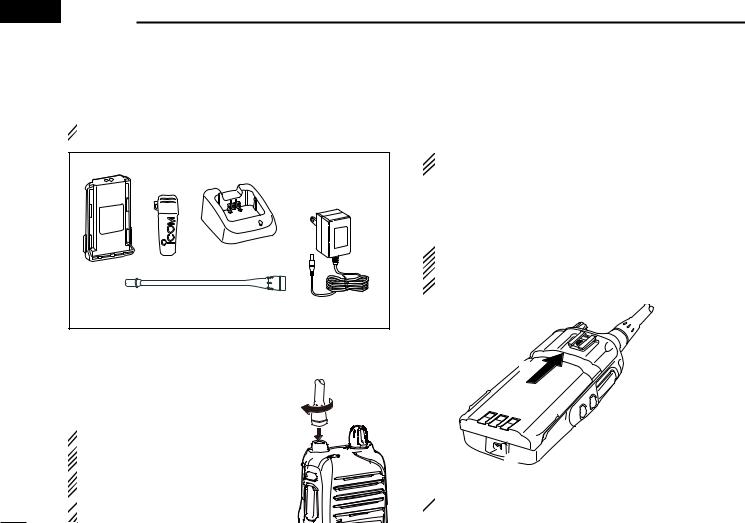
■■Supplied accessories
 NOTE: Some accessories are not supplied with depending
  on versions.
Battery pack |
Battery charger* |
Belt clip |
Power adapter* |
|
(for the battery charger) |
Flexible antenna
*Not supplied, or shape is different, depending on the transceiver version.
■■Accessory attachments
DDFlexible antenna
Connect the supplied flexible antenna to the antenna connector.
 CAUTION:
 • NEVER carry the transceiver by
holding the antenna.
 • DO NOT connect the antenna other
than listed on page 27.
 • Transmitting without an antenna
  may damage the transceiver.
DDBattery pack
To attach the battery pack:
Slide the battery pack in the direction of the arrow (q) until the battery release button makes a ‘click’ sound.
 NOTE: Push on the bottom of the pack to make sure the
  release button is firmly locked.
To release the battery pack:
Slide the battery release button in the direction of the arrow (w) as shown below. The battery pack is then released.
 NEVER release or attach the battery pack when the
transceiver is wet or soiled. This may result water or dust
 getting into the transceiver/battery pack and may result in
  the transceiver being damaged.
q

 Battery release button
  w
w
 NOTE: Keep the battery terminals clean. It's a good idea
  to occasionally clean them.
1

DDBelt clip
To attach the belt clip:
qqRelease the battery pack if it is attached.
wwSlide the belt clip in the direction of the arrow until the belt clip is locked and makes a ‘click’ sound.
To detach the belt clip:
qqRelease the battery pack if it is attached.
wwPinch the clip (q), and slide the belt clip in the direction of the arrow (w).
w
q

ACCESSORIES 1
DDJack cover |
1 |
To attach the jack cover:
q Attach the jack cover to the [MIC/SP] jack. w Tighten the screws.
[MIC/SP] jack
q  w
w
 CAUTION:
 • Attach the jack cover when the op-
tional speaker-microphone is not
used.
 • Use the supplied screws only.
To detach the jack cover:
q Unscrew the screws using a phillips screwdriver.
w Detach the jack cover for the speak- er-microphone or headset connection.
Jack cover
q
 w
w
q
2
 2 PANEL DESCRIPTION
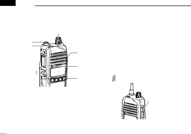
■■Front panel
o
q w
e i
i
r
 Speaker
Microphone

 u t
u t
y
q ANTENNA CONNECTOR
Connects the supplied antenna.
w DEALER-PROGRAMMABLE KEY [Emer]
Desired function can be programmed by your dealer. (p. 7)
e DEALER-PROGRAMMABLE KEY [Side1]
Desired function can be programmed by your dealer. (p. 5)
r PTT SWITCH [PTT]
Hold down to transmit. Release to receive.
t DEALER-PROGRAMMABLE KEYS [Side2]/[Side3]
Desired functions can be programmed independently by your dealer. (p. 5)
y DEALER-PROGRAMMABLE KEYS [P0] to [P3]
Desired functions can be programmed independently by your dealer. (p. 5)
u FUNCTION DISPLAY (p. 4)
Displays a variety of information such as an operating channel number/name, 2-Tone code, DTMF numbers, selected function and so on.
i EXTERNAL MICROPHONE/SPEAKER JACK
Connect an optional speaker-microphone.
 NOTE: Connect or disconnect the optional equipment after the transceiver is turned OFF.
Jack cover
NOTE: Attach the jack cover when the optional equipment is not used.
Refer to page 2 for details.
o VOLUME CONTROL [VOL]
Rotate to turn the power ON/OFF and adjusts the audio level.
3
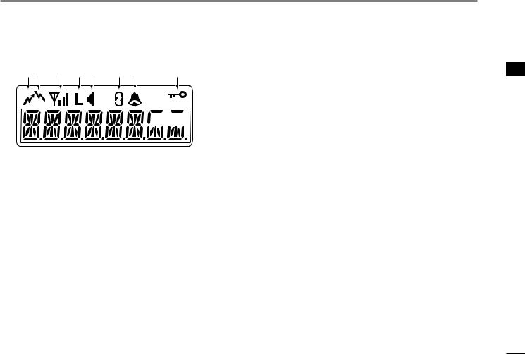
■■Function display
q w e r t y u |
i |

 o
o 


 !0
!0
q TRANSMIT INDICATOR
Displayed while transmitting. w BUSY INDICATOR
Displayed while the channel is busy. e SIGNAL STRENGTH INDICATOR
Displays relative signal strength level. r LOW POWER INDICATOR
Displayed when low output power is selected.
•When the battery power decreases to a specified level, low power is selected automatically.
t AUDIBLE INDICATOR
Displayed when the channel is in the ‘audible’ (unmute) condition.
Displayed when the specified 2-Tone code is received.
PANEL DESCRIPTION 2
2
y SCRAMBLER INDICATOR
Displayed when the voice scrambler function is activated. u BELL INDICATOR
Displayed or blinks when the specific 2-Tone code is received, according to the pre-programming.
i KEY LOCK INDICATOR
Displayed during the key lock function is ON. o BATTERY INDICATOR
Displayed or blinks when the battery power decreases to a specified level.
!0ALPHANUMERIC DISPLAY
Displays an operating channel number, channel name, Set mode contents, DTMF code, etc.
4

2 PANEL DESCRIPTION
■■Programmable function keys
The following functions can be assigned to [Emer], [Side1],
[Side2], [Side3], [P0], [P1], [P2] and [P3] programmable function keys.
Consult your Icom dealer or system operator for details concerning your transceivers programming.
If the programmable function names are bracketed in the following explanations, the specific key is used to activate the function depends on the programming.
CH UP AND DOWN KEYS
Push to select an operating channel.
Push to select a transmit code channel after pushing [TX Code CH Select].
Push to select a DTMF channel after pushing [DTMF Autodial].
Push to select a scan group after pushing and holding [Scan A Start/Stop]/[Scan B Start/Stop] for 1 second.
SIREN KEY
Push to emit a siren.
ZONE KEY
Push this key, then push [CH Up] or [CH Down] to select the desired zone.
 What is “zone”?— The desired channels are assigned into a zone according to the intended use for grouping. For example, ‘Staff A’ and ‘Staff B’ are assigned into a “Business” zone, and ‘John’ and ‘Cindy’ are assigned into
  a “Private” zone.
SCAN A KEY
This key’s operation depends on the Power ON Scan setting.
When the power ON scan function is turned OFF:
Push to start and cancel scanning operation. In case of transmission during scan, scanning will be cancelled.
When the power ON scan function is turned ON:
Push to pause scanning, then resumes scanning after passing a specified time period. In case of transmission during scan, scanning will be cancelled.
Hold down this key for 1 second to indicate the scan group, then push [CH Up] or [CH Down] to select the desired group.
SCAN B KEY
Push to start and cancel scanning operation. In case of transmission during scan, scanning will be paused. Then resumes scanning after passing a specified time period.
Hold down this key for 1 second to indicate the scan group, then push [CH Up] or [CH Down] to select the desired group.
PRIO A/B KEYS
Push to select Priority A or Priority B channel.
Hold down [Prio A (Rewrite)] or [Prio B (Rewrite)] for 1 second to reassign the operating channel to Priority A or Priority B channel.
5
SCAN ADD/DEL (TAG) KEY
Push to add a channel to, or delete it from the current scan list.
•When a channel is added to the current scan list, the display shows “SCAN ON.” When a channel is deleted from the current scan list, the display shows “SCAN OFF.” After showing “SCAN ON” or “SCAN OFF,” the display shows the current scan list text.
You can add a channel to, or delete it from the scan list after selecting the list.
1. Hold down for 1 second to display the current scan list, and then push [CH Up] or [CH Down] to select a desired list.
2. Push this key to add a channel to, or delete it from the selected list.
3. Hold down this key for 1 second to exit the scan list selection mode.
Push this key while a scan is paused on a channel, except for primary or secondary channel, and then the channel is deleted from the scan list.
•Depending on the setting, the deleted channel is added to the scan list again after the scan is cancelled. (Nuisance Delete function)
C.TONE CH ENT KEY
Push to select the continuous tone channel using [CH Up]/ [CH Down] to change the tone frequency/code setting. The selected channel remains set as the continuous tone channel until another channel is designated as such.
PANEL DESCRIPTION |
2 |
|
|
MR-CH 1/2/3/4 KEYS |
|
|
|
Push to select memory channels 1 to 4 in the operating zone |
|
||
2 |
|||
directly. |
|
||
MONI KEY
Mute and release the CTCSS (DTCS) or 2-Tone squelch mute. Open any squelch/deactivate any mute while pushing and holding this key.
LOCK KEY
Hold down for 1 second to electronically lock all programmable keys except the following:
[Call] (incl. Call A and Call B), [Moni], [Emergency], [Surveillance], [Siren], [Lone Worker] and [OPT 1/2/3].
Hold down for 1 second again to turn the lock function OFF.
HIGH/LOW KEY
Push to select the transmit output power temporarily or permanently, depending on the presetting.
• Ask your dealer for the output power level for each selection.
OPT MOMENTARY KEYS
Controls the output signal level of the optional ports in the optional unit connector while pushing and holding this key.
OPT OUT KEYS
Push to control the output signal level of the optional ports in the optional unit connector.
SCRAMBLER FUNCTION
Push to toggle the voice scrambler function ON and OFF.
6

2 PANEL DESCRIPTION
TALK AROUND KEY
Push to turn the talk around function ON and OFF.
• The talk around function equalizes the transmit frequency to the receive frequency for transceiver-to-transceiver communication.
WIDE/NARROW KEY
Push to toggle the IF bandwidth between wide and narrow.
DTMF AUTODIAL KEY
Push to enter the DTMF channel selection mode. Then select the desired DTMF channel using [CH Up]/[CH Down].
After selecting the desired DTMF channel, push this key to transmit the DTMF code.
RE-DIAL KEY
Push to transmit the last-transmitted DTMF code.
CALL KEYS
Push to transmit a 2-Tone.
• Call transmission is necessary before you call another station depending on your signaling system.
• [Call A] and/or [Call B] may be available when your system employs selective ‘Individual/Group’ calls. Ask your dealer which call is assigned to each key.
LONE WORKER KEY
Push to turn the Lone Worker function ON or OFF.
•If the Lone Worker function is activated, the Emergency function is automatically turned ON after the specified time period has passed with no operation is performed.
TX CODE CHANNEL UP/DOWN KEYS
Push to select a TX code channel directly.
EMERGENCY KEY
Hold down to transmit the emergency call.
•The transceiver can transmit the emergency call silently or audibly depending on the presetting. Ask your dealer for details.
•When the emergency call transmits with beeps, the emergency text is displayed on the LCD if programmed.
•If you want to cancel the emergency call, hold down the key again before transmitting the call.
•The emergency call is transmitted one time only or repeatedly until receiving a control code, depending on the presetting.
SURVEILLANCE KEY
Push to turn the surveillance function ON or OFF.
When this function is turned ON, the beep is not emitted and the LCD backlight does not light when a signal is received or a key is pushed, etc.
TX CODE CHANNEL SELECT KEY
Push to enter the ID code channel selection mode directly. Then set the desired channel using [CH Up]/[CH Down]. (p. 11)
USER SET MODE KEY
Hold down for 1 second to enter user set mode.
•During in the user set mode, push this key to select an item that is enabled by your dealer, and change the value or condition by pushing [CH Up] or [CH Down].
Hold down this key for 1 second again to exit user set mode.
7
Loading...