


INSTRUCTION MANUAL
VHF TRANSCEIVER
iF310
iF320
UHF TRANSCEIVER
iF410
iF420
This device complies with Part 15 of the FCC Rules. Operation is subject to the condition that this device does not cause harmful interference.

IMPORTANT
READ ALL INSTRUCTIONS carefully and com-
pletely before using the transceiver.
SAVE THIS INSTRUCTION MANUAL — This
instruction manual contains important operating instructions for the IC-F310, IC-F320, IC-F410 and IC-F420 VHF/UHF TRANSCEIVERS.
EXPLICIT DEFINITIONS
WORD |
DEFINITION |
|
RWARNING |
Personal injury, fire hazard or electric shock |
|
may occur. |
||
|
|
|
CAUTION |
Equipment damage may occur. |
|
NOTE |
If disregarded, inconvenience only. No risk |
|
of personal injury, fire or electric shock. |
||
|
||
|
|
Versions of the IC-F310/F320/F410/F420 which display “CE” on the serial number seal, comply with the essential requirements of the 89/336/EEC directive for Electromagnetic Compatibility.
i
CAUTIONS
RWARNING! NEVER connect the transceiver to an AC outlet. This may pose a fire hazard or result in an electric shock.
NEVER connect the transceiver to a power source of more than 16 V DC such as a 24 V battery. This connection will ruin the transceiver.
NEVER cut the DC power cable between the DC plug and fuse holder. If an incorrect connection is made after cutting, the transceiver might be damaged.
NEVER place the transceiver where normal operation of the vehicle may be hindered or where it could cause bodily injury.
NEVER allow children to touch the transceiver.
NEVER expose the transceiver to rain, snow or any liquids.
USE supplied microphone only. Other microphones have different pin assignments and may damage the transceiver.
SmarTrunk II™ is a Trademark of SmarTrunk Systems, Inc.

DO NOT use or place the transceiver in areas with temperatures below –30°C or above +60°C or, in areas subject to direct sunlight, such as the dashboard.
AVOID operate the transceiver without running the vehicle’s engine. The vehicle’s battery will quickly run out if the transceiver is in transmission while the vehicle’s engine OFF.
AVOID placing the transceiver in excessively dusty environments.
AVOID placing the transceiver against walls. This will obstruct heat dissipation.
AVOID the use of chemical agents such as benzine or alcohol when cleaning, as they damage the transceiver surfaces.
BE CAREFUL! The transceiver will become hot when operating continuously for long periods.
For U.S.A. only
CAUTION: Changes or modifications to this transceiver, not expressly approved by Icom Inc., could void your authority to operate this transceiver under FCC regulations.
TABLE OF CONTENTS |
|
|
IMPORTANT ........................................................................ |
i |
|
EXPLICIT DEFINITIONS ..................................................... |
i |
|
CAUTIONS .......................................................................... |
i |
|
TABLE OF CONTENTS ...................................................... |
ii |
|
1 |
PANEL DESCRIPTION ............................................. |
1–5 |
|
■ Front panel ............................................................................ |
1 |
|
■ Function display .................................................................... |
2 |
|
■ Programmable function keys ................................................ |
3 |
2 |
OPERATION ............................................................. |
6–8 |
|
■ Turning power ON ................................................................ |
6 |
|
■ Channel selection ................................................................. |
6 |
|
■ Receiving and transmitting ................................................... |
7 |
|
DTransmitting notes .......................................................... |
7 |
|
DTx code channel selection .............................................. |
8 |
|
DTx code number selection .............................................. |
8 |
|
DDTMF transmission ........................................................ |
8 |
3 |
CONNECTION AND MAINTENANCE .................... |
9–12 |
|
■ Rear panel and connection ................................................... |
9 |
|
■ Unpacking ........................................................................... |
10 |
|
■ Mounting the transceiver...................................................... |
11 |
|
■ Optional UT-96/UT-105 installation ..................................... |
11 |
|
■ Optional OPC-617 installation ............................................. |
12 |
|
■ Antenna ............................................................................... |
12 |
|
■ Fuse replacement ............................................................... |
12 |
|
■ Cleaning ............................................................................. |
12 |
4 OPTIONAL SmarTrunk II™ OPERATION ........... |
13–15 |
|
|
■ SmarTrunk II™ and conventional modes ........................... |
13 |
|
■ SmarTrunk II™ operation ................................................... |
13 |
5 |
OPTIONS .................................................................... |
16 |
ii

 1 PANEL DESCRIPTION
■Front panel
VOLUME UP/DOWN KEYS (P. 2) |
FUNCTION DISPLAY (P. 2) |
CH UP/DOWN KEYS [ ]/[ ] (P. 3) |
MICROPHONE |
PROGRAMMABLE |
POWER SWITCH (P. 2) |
CONNECTOR (P. 2) |
FUNCTION KEYS [P0],[P1],[P2],[P3] (P. 3) |
|
1
VOLUME UP/ DOWN KEYS
Push to adjust the audio output level.
• Minimum audio level is pre-programmed.
CH UP/DOWN [ ]/[
]/[ ] KEYS
• Push to select the operating channel.
•Can be programmed for one of several functions by yourdealer.
POWER SWITCH
Turns the power ON and OFF.
•The following functions are available at power ON as options:
•Automatic scan start
•Password prompt
MICROPHONE CONNECTOR
Connect the supplied microphone or optional DTMF microphone for SmarTrunk II™ operation here.
NEVER connect other microphones. The pin assignments may be different and the transceiver may be damaged.
MICROPHONE
The supplied microphone has a PTT switch and a hanger hook.
•The following functions are available when the microphone is on or off hook:
•Automatic scan start when hung on.
•Automatic priority channel selection when off.
•Sets to ‘Inaudible’ condition (mute condition) when hung on.
•Sets to ‘Audible’ condition (unmute condition) when off.
PANEL DESCRIPTION 1
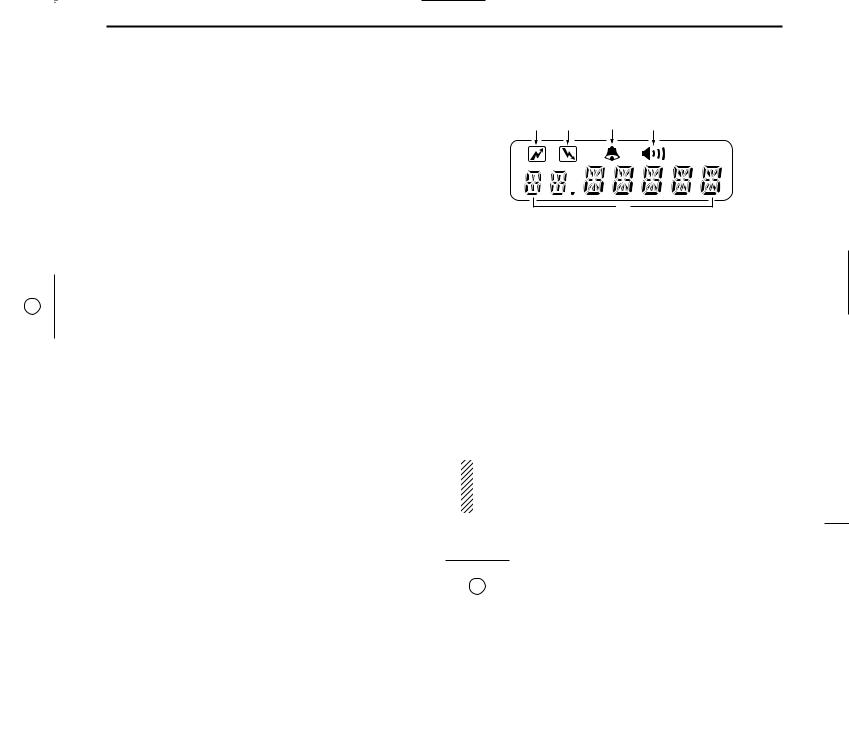
■Function display
q w e r
t
qTRANSMIT INDICATOR
• Appears while transmitting or sending a 5-tone code. •When internal temperature increases to a specific level, the transmit indicator blinks to indicate that the power down circuit has been activated.
wBUSY INDICATOR
Appears while the channel is busy.
eBELL INDICATOR
Appears or blinks when the specified 5-tone call is received.
rAUDIBLE INDICATOR
Appears when the channel is in the ‘Audible’ condition (unmute condition).
tALPHANUMERIC DISPLAY
NOTE: When the alphanumeric display blinks transmitting becomes impossible. In this case check that the antenna is not mis-matched or that DC battery voltage has not dropped below 8 V.
2

1 PANEL DESCRIPTION
■Programmable function keys
The following functions can be assigned to [P0], [P1], [P2], [P3], [ ] and [
 ] programmable function keys.
Consult your Icom Dealer or System operator for details concerning your transceivers programming.
In the following explanations, programmable function names are bracketed, the specifc switch used to activate the function depends on programming.
CH UP CH UP AND DOWN KEYS
• Select an operating channel.
CH DN • Select a transmit code channel after pushing the [TX CH] key.
•Select a DTMF channel after pushing the [DTMF] key.
•Select a scan group after pushing and holding the [SCAN] key.
CH 1 OPERATING CHANNEL KEYS
CH 2 Select an operating channel directly.
CH 3
CH 4
PRI A PRIORITY CHANNEL KEYS
Select priority A or priority B channel with each push.
PRI B
BANK BANK KEY
Select a bank (a group of 16 channels).
•When the optional UT-105 is installed, push one or more times to select a channel bank for conventional channels or SmarTrunk II™ channels.
SCAN SCAN START/STOP KEY
Push this key to start scanning; and push again to stop.
NOTE: Place the microphone on hook to start scanning.
Take the microphone off hook to stop scanning.
Push and hold this key to indicate the scan group, then push to select the desired group.
TAG SCAN TAG KEY
Adds or deletes the selected channel to the scan group.
BEEP BEEP
Push to turn the beep tones ON/OFF.
3

LOCK LOCK KEY
Electronically locks all programmable keys except the following:
•[CALL] (incl. CAL A and CAL B), [MONI] and [EMER] keys.
MONI MONITOR KEY
Activates one of (or two of) the following functions on each channel independently:
•Push and hold the key to unmute the channel (audio is emitted; ‘Audible’ condition).
•Push the key to toggle the mute and unmute conditions (toggles ‘Audible’ and ‘Inaudible’).
•Push the key to mute the channel (sets to ‘Inaudible’ only).
•Push the key to unmute the channel (sets to ‘Audible’ only).
•Push the key after the communication is finished to send a ‘reset code’.
NOTE: The unmute condition (‘Audible’ condition) may automatically return to the mute condition (‘Inaudible‘ condition) after a specified period.
W/N WIDE/NARROW KEY
Push [W/N] to toggle bandwidth between wide or
narrow.
• This function is available for W/N versions only.
|
|
PANEL DESCRIPTION 1 |
|
|
OUTPUT POWER SELECTION KEYS |
|
HIGH |
|
|
Select the transmit output power temporarily or per- |
|
|
|
|
|
LOW1 |
manently depending on the pre-setting. |
|
|
|
|
|
• Ask your Dealer or System Operator for the output power |
|
LOW2 |
|
|
|
level for each selection. |
|
|
TALK AROUND KEY |
|
T A |
|
|
|
Turns the talk around function ON and OFF. |
|
|
• The talk around function equalizes the transmit frequency |
|
|
to the receive frequency for mobile-to-mobile communica- |
|
|
tion. |
|
|
CALL KEYS |
|
CALL |
|
|
|
Transmit a 5-tone call. |
|
CAL A |
|
|
• Call transmission is necessary before you call another sta- |
|
|
|
|
|
|
|
|
CAL B |
tion depending on your signaling system. |
|
|
• The [CAL A] and/or [CAL B] keys may be available when |
|
|
your system employs selective ‘Individual/Group’ calls. |
|
|
Ask your System Operator which call is assigned to each |
|
|
key. |
|
|
EMERGENCY KEY |
|
EMER |
|
|
|
Push and hold the key to transmit an emergency call. |
• If you want to cancel the emergency call, push (or push and hold) the key again before transmitting the call.
• The emergency call is transmitted one time only or repeatedly until receiving a control code depending on the pre-setting.
4

1 PANEL DESCRIPTION
TX CH TX CODE KEY
Select a transmit 5-tone code (station code) channel. •Push and hold to changes the contents of the station code using [ ]/[
]/[ ] keys.
•Push to selects a TX 5-tone code channel using [ ]/[
]/[ ] keys after pushing this key.
CODE TX CODE CHANNEL UP/DOWN KEY
Push to selects a TX code channel directory.
DTMF DTMF CHANNEL SELECT KEY
Push this key to select a DTMF channel.
• Push this key, then select the desired DTMF channel using the [ ]/[
]/[ ] keys.
Push and hold this key to transmit the selected DTMF code.
NOTE: DTMF channels 6 and 7 are used for ID code and emergency code respectively, depending on your system set up.
Ask your System Operator or Dealer about DTMF channels 6 and 7 before using these.
TONE C. TONE CHANNEL ENTER KEY
Push this key then input a continuous tone memory channel number via the keypad to change the tone frequency.
ID MR ID MEMORY READ KEY
Recalls detected ID codes.
•Push this key, then push [ ]/[
]/[ ] for selection.
•Up to 5 ID's are memorized.
Push and hold this key to erase all memorized IDs.
LITE LIGHT
Push to select the backlight condition.
ON |
:Turns ON the backlight continuously. |
OFF |
:Turns OFF the backlight. |
AUTO |
:Turns ON/OFF depending on the ACC |
|
socket pin 1 voltage. |
|
ON: Low (0 V) OFF: High (12 V) |
ATT ATTENUATOR
Push to turn the attenuator function ON/OFF.
NOTE: The attenuator function protects desired signals from distorting when excessively strong signals, such as broadcast, pager signals, etc. are nearby.
GRP TRUNKING GROUP SWITCH
Push to select the Trunking group.
5
 Loading...