


INSTRUCTION MANUAL
VHF TRANSCEIVER
iF51
UHF TRANSCEIVER
iF61

FOREWORD
READ ALL INSTRUCTIONS carefully and completely before using the transceiver.
SAVE THIS INSTRUCTION MANUAL— This instruction manual contains important operating instructions for the IC-F51 VHF
TRANSCEIVER and IC-F61 UHF TRANSCEIVER.
EXPLICIT DEFINITIONS
WORD |
DEFINITION |
RWARNING
Personal injury, fire hazard or electric shock may occur.
CAUTION Equipment damage may occur.
NOTE
If disregarded, inconvenience only. No risk of personal injury, fire or electric shock.
OPERATING NOTES
•When transmitting with a portable radio, hold the radio in a vertical position with its microphone 5 to 10 centimeters away from your mouth. Keep the antenna at least 2.5 centimeters from your head and body.
•If you wear a portable two-way radio on your body, ensure that the antenna is at least 2.5 centimeters from your body when transmitting.
i

PRECAUTION
R WARNING! NEVER hold the transceiver so that the antenna is very close to, or touching exposed parts of the body, especially the face or eyes, while transmitting. The transceiver will perform best if the microphone is 5 to 10 cm away from the lips and the transceiver is vertical.
R WARNING! NEVER operate the transceiver with a headset or other audio accessories at high volume levels.
CAUTION! NEVER short the terminals of the battery pack.
NEVER connect the transceiver to a power source other than the BP-226 or BP-227. Such a connection will ruin the transceiver.
DO NOT push the PTT when not actually desiring to transmit.
AVOID using or placing the transceiver in direct sunlight or in areas with temperatures below –25°C or above +55°C.
The basic operations, transmission and reception of the transceiver, are guaranteed within the specified operating temperature range (depending on version). However, the LCD display may be operate correctly, or show an indication in the case of long hours of operation, or after being placed in extremely cold areas.
DO NOT modify the transceiver for any reason.
MAKE SURE the flexible antenna and battery pack are securely attached to the transceiver, and that the antenna and battery pack are dry before attachment. Exposing the inside of the transceiver to water will result in serious damage to the transceiver.
The use of non-Icom battery packs/chargers may impair transceiver performance and invalidate the warranty.
ii

TABLE OF CONTENTS
FOREWORD ……………………………………………………………… i EXPLICIT DEFINITIONS ………………………………………………… i OPERATING NOTES ……………………………………………………… i PRECAUTION …………………………………………………………… ii TABLE OF CONTENTS ………………………………………………… iii SUPPLIED ACCESSORIES …………………………………………… iv
1 ACCESSORIES ……………………………………………………… 1–2
‘Accessory attachments ……………………………………………… 1
2 PANEL DESCRIPTION …………………………………………… 3–11
‘Front, top and side panels ………………………………………… 3
‘Function display ……………………………………………………… 6
‘Programmable function keys ……………………………………… 7
3 CONVENTIONAL OPERATION ………………………………… 12–18
‘Turning power ON ………………………………………………… 12
‘Channel selection ………………………………………………… 12
‘Call procedure ……………………………………………………… 13
‘ Receiving and transmitting ……………………………………… 14
‘Scrambler function ………………………………………………… 17
‘User set mode ……………………………………………………… 18
4 BIIS OPERATION ………………………………………………… 19–34
‘Default setting ……………………………………………………… 19
‘Receiving a call …………………………………………………… 20
‘Transmitting a call ………………………………………………… 23
‘Receiving a message ……………………………………………… 26
‘Transmitting a status ……………………………………………… 29
‘Transmitting an SDM ……………………………………………… 30
‘Position data transmission ………………………………………… 31
‘Printer connection ………………………………………………… 32
‘PC connection ……………………………………………………… 32
‘Digital ANI …………………………………………………………… 32
‘Auto emergency transmission …………………………………… 33
‘Stun function………………………………………………………… 33
‘BIIS indication ……………………………………………………… 34
‘ Priority A channel selection ……………………………………… 34
iii

5 BATTERY CHARGING ………………………………………… 35–44
‘Battery charging …………………………………………………… 35
‘Caution ……………………………………………………………… 36
‘Optional battery chargers ………………………………………… 37
‘Optional battery case ……………………………………………… 43
6 SPEAKER-MICROPHONE ……………………………………… 45–46
‘Optional HM-138 description ……………………………………… 45
‘Attachment ………………………………………………………… 46
7 OPTIONS ………………………………………………………… 47–48
8 DOC………………………………………………………………… 49–50
SUPPLIED ACCESSORIES |
|
The following accessories are supplied: |
Qty. |
• Flexible antenna . . . . . . . . . . . . . . . . . . . . . . . . . . . . . . . . . . |
. . .1 |
• Battery pack . . . . . . . . . . . . . . . . . . . . . . . . . . . . . . . . . . . . . |
. . .1 |
• Jack cover . . . . . . . . . . . . . . . . . . . . . . . . . . . . . . . . . . . . . . . |
1 set |
• Belt clip . . . . . . . . . . . . . . . . . . . . . . . . . . . . . . . . . . . . . . . . . |
1 set |
• Function name stickers* (KEY-STICKER) . . . . . . . . . . . . . . . |
. . .1 |
*There are no names on the programmable function keys since the functions can be freely assigned to [P0] to [P3], [Red], [ ] and [
 ] keys.
Attach the supplied function name stickers above the appropriate keys for easy recognition of that key’s assigned function.
iv
1 ACCESSORIES
■ Accessory attachments
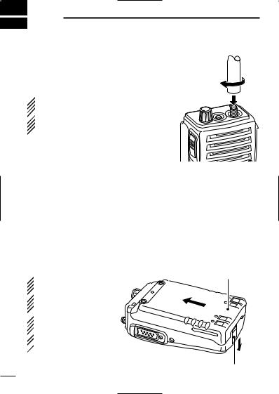
D Flexible antenna
Connect the supplied flexible antenna to the antenna connector.
 CAUTION!
• NEVER HOLD by the antenna  when carrying the transceiver.
• Transmitting without an antenna  may damage the transceiver.
ï Battery pack
To attach the battery pack:
Slide the battery pack on the back of the transceiver in the direction of the arrow (q), then lock it with the battery release button.
•Slide the battery pack until the battery release button makes a ‘click’ sound.
To release the battery pack:
Push the battery release button in the direction of the arrow (w) as shown below. The battery pack is then released.
 NEVER release or at-
tach the battery pack
 when the transceiver
is wet or soiled. This
 may result in water or
dust getting into the
 transceiver/battery
  pack and may dam-
  age the transceiver.
Battery pack
q
w
Battery release button
1

|
ACCESSORIES 1 |
|
ï Jack cover |
|
|
|
1 |
|
Attach the jack cover when the optional speaker-microphone is not |
|
|
used. |
|
|
To attach the jack cover: |
To detach the jack cover: |
|
q Insert the jack cover into the |
e Unscrew the screw with a |
|
[SP MIC] connector. |
phillips screwdriver. |
|
w Tighten the screw. |
r Detach the jack cover for the |
|
|
speaker-microphone connec- |
|
|
tion. |
|
q
r
 e
e
w
D Belt clip
Attach the belt clip to the back of the transceiver with the supplied screws.
 Supplied screws
2
2 PANEL DESCRIPTION
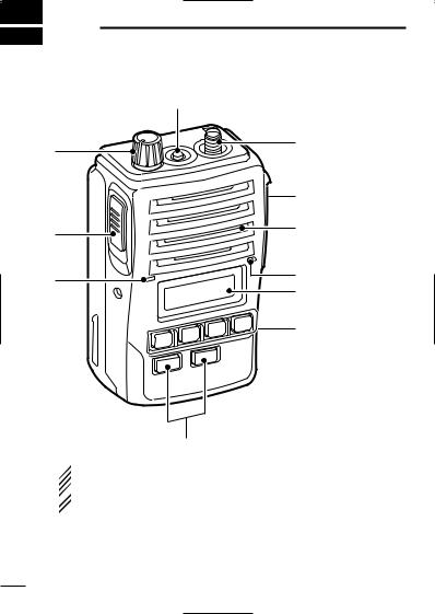
■ Front, top and side panels
|
w |
|
q |
e |
|
|
||
|
r |
|
i |
Speaker |
|
(See the following |
||
|
||
|
NOTE.) |
|
u |
Microphone |
|
Function display |
||
|
||
|
(p. 6) |
|
|
t |
y
 NOTE: If the speaker netting (for dust proofing) becomes wet,
dry it with a hair drier (cool mode) etc. before operating the
 transceiver. Otherwise the audio may be difficult to hear for
  loss of the sound pressure.
3
PANEL DESCRIPTION |
2 |
q VOLUME CONTROL [VOL] |
2 |
Turns power ON and adjusts the audio level.
w RED BUTTON
The desired function can be assigned by your dealer.
e ANTENNA CONNECTOR
Connects the supplied antenna.
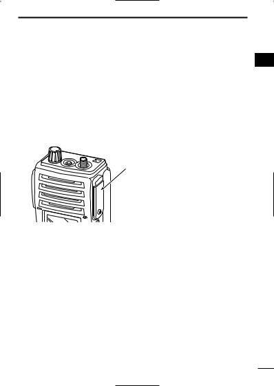
r SPEAKER-MICROPHONE CONNECTOR [SP MIC]
Connects the optional speaker-microphone. (p. 46)
[SP MIC] jack cover
NOTE: KEEP the [SP MIC] jack cover attached to the transceiver when the speakermicrophone is not used.
(See p. 2 for details)
t DEALER-PROGRAMMABLE KEYS [P0] to [P3]
The desired functions can be assigned independently by your dealer.
y CH UP AND DOWN KEYS [ ]/[
]/[ ]
]
During standby condition, push to select an operating channel.
After pushing [TX Code CH Select], push to select a TX code channel.
After pushing [DTMF Autodial], push to select a DTMF channel.
After pushing and holding [Scan A Start/Stop]/[Scan B Start/Stop], push to select a scan group.
After pushing [Digital], push to select a BIIS code, status num-
ber or SDM.
*Desired functions can be assigned independently by your dealer.
Continue to the next page.
4

2 PANEL DESCRIPTION
■ Front, top and side panels (Continued)
u TRANSMIT/BUSY INDICATOR
Lights red while transmitting; lights green while receiving a signal, or when the squelch is open.
i PTT SWITCH [PTT]
Push and hold to transmit; release to receive.
5
PANEL DESCRIPTION 2
■ Function display
q w e r t y u |
2 |
i |
q OUTPUT POWER INDICATOR
Appears when Low 2 or Low 1 is selected.
w AUDIBLE INDICATOR
Appears when the channel is in the ‘audible’ (unmute) condition.
Appears when the specified 5-tone/BIIS code is received.
e COMPANDER INDICATOR
Appears when the compander function is activated.
r KEY LOCK INDICATOR
Appears during the key lock function ON.
t SCRAMBLER INDICATOR
Appears when the voice scrambler function is activated.
y BELL INDICATOR
Appears/Blinks when the specific 5-tone/BIIS code is received, according to the programming.
u BATTERY INDICATOR
Appears or blinks when the battery power decreases to a specified level.
i ALPHANUMERIC DISPLAY
Displays the operating channel number, channel names, Set mode contents, DTMF numbers, etc.
6

2 PANEL DESCRIPTION
■ Programmable function keys
The following functions can be assigned to [P0], [P1], [P2], [P3], [Red], [ ] and [
 ] programmable function keys.
Consult your Icom dealer or system operator for details concerning your transceivers programming.
If the programmable function names are bracketed in the following explanations, the specific switch used to activate the function depends on programming.
CH UP AND DOWN KEYS
•Select an operating channel.
•Select a transmit code channel after pushing the [TX Code CH Select] keys.
•Select a DTMF channel after pushing the [DTMF Autodial] key.
•Select a scan group after pushing and holding the [Scan A Start/Stop]/[Scan B Start/Stop] keys.
•Select a BIIS code, status number or SDM after pushing the [Digital] key.
BANK SELECT KEY
Push this key, then push [CH Up] or [CH Down] to select the desired bank.
SCAN START/STOP KEYS
Push this key to start scanning; and push again to stop.
Push and hold this key to indicate the scan group, then select the desired scan group using [CH Up]/[CH Down].
SCAN TAG KEY
Adds or deletes the selected channel to the scan group.
7

PANEL DESCRIPTION |
2 |
PRIORITY CHANNEL KEYS |
2 |
Push to select Priority A or Priority B channel.
Push and hold [Prio A (Rewrite)] to rewrite the Prio A channel.
MR-CH 1/2/3/4 KEYS
Select an operating channel directly.
MONITOR KEY
Activates one of (or two of) the following functions on each channel independently:
•Push and hold to un-mute the channel (audio is emitted; ‘Audible’ condition).
•Push to mute the channel (sets to ‘Inaudible’ only).
•Push to un-mute the channel (sets to ‘Audible’ only).
•Push after the communication is finished to send a ‘reset code’.
 NOTE: The un-mute condition (‘Audible’ condition) may auto-
  matically return to the mute condition (‘Inaudible’ condition) after
  a specified period.
LOCK KEY
Push and hold to electronically lock all programmable keys except the following:
[Call] (incl. Call A and Call B), [Moni(Audi)] and [Emergency] keys.
OUTPUT POWER SELECTION KEY
Select the transmit output power temporarily or permanently, depending on the pre-setting.
• Ask your dealer for the output power level for each selection.
8

2 PANEL DESCRIPTION
C.TONE CHANNEL ENTER KEY
Select the continuous tone channel using [CH Up]/[CH Down] keys to change the tone frequency/code setting after pushing this key for permanent operation.
TALK AROUND KEY
Turn the talk around function ON and OFF.
•The talk around function equalizes the transmit frequency to the receive frequency for transceiver-to-transceiver communication.
WIDE/NARROW KEY
Push to toggle the IF bandwidth between wide and narrow.
•The wide passband width can be selected from 25.0 or 20.0 kHz using the CS-F50 CLONING SOFTWARE. Ask your dealer for details.
DTMF AUTODIAL KEY
Push to enter the DTMF channel selection mode. Then select the desired DTMF channel using [CH Up]/[CH Down] keys.
After selecting the desired DTMF channel, push this key to transmit the DTMF code.
DTMF RE-DIAL KEY
Push to transmit the last-transmitted DTMF code.
CALL KEYS
Push to transmit a 5-tone/BIIS ID code.
•Call transmission is necessary before you call another station depending on your signalling system.
•The [Call A] and/or [Call B] keys may be available when your system employs selective ‘Individual/Group’ calls. Ask your dealer which call is assigned to each key.
9

PANEL DESCRIPTION 2
EMERGENCY KEYS
Push and hold to transmit an emergency call.
When [Emergency Single (Silent)] or [Emergency Repeat 2 (Silent)] is pushed, an emergency call is transmitted without a beep emission and LCD indication change.
•If you want to cancel the emergency call, push (or push and hold) the key again before transmitting the call.
•The emergency call is transmitted one time only or repeatedly until receiving a control code depending on the pre-setting.
TX CODE ENTER KEY
Push to enter the direct ID code edit mode, for both 5-tone and MSK. Then set the desired digit using [CH Up]/[CH Down]/ [TX Code CH Up]/[TX Code CH Down]. (p. 16)
TX CODE CHANNEL SELECT KEY
Push to enter the direct ID code channel selection mode. Then set the desired channel using [CH Up]/[CH Down]/[TX Code CH Up]/[TX Code CH Down]. (p. 15)
While in ID code channel selection mode, push for 1 sec. to enter the ID code edit mode. Then set the desired digit using [CH Up]/[CH Down]/[TX Code CH Up]/[TX Code CH Down]. (p. 16)
TX CODE CHANNEL UP/DOWN KEYS
Push to select a TX code channel directly.
ID MEMORY READ KEY
Recalls detected ID codes.
•Push this key, then push [CH Up]/[CH Down] for selection.
•Up to 5 ID’s are memorized.
Push and hold to erase the selected memorized ID’s.
10

2 PANEL DESCRIPTION
VOICE SCRAMBLER FUNCTION
Push to toggle the voice scrambler function ON and OFF.
COMPANDER KEY
Push to toggle the compander function ON and OFF.
The compander function reduces noise components from the transmitting audio to provide clear communication.
USER SET MODE KEY
Push and hold to enter user set mode.
•During user set mode, push this key to select an item, and push [CH Up]/[CH Down] to change the value or condition.
Push and hold this key again to exit user set mode.
•User set mode is also available via the ‘Power ON function’. Please refer to p. 18 also.
DIGITAL KEY (BIIS operation only)
Push to select the call ID list, transmit message and standby condition. Toggles between queue channel and received message record indication after queue channel is selected.
Push and hold to select queue channel indication.
STATUS UP/DOWN KEYS (BIIS operation only)
While in the standby condition, push to display the transmit status indication and select a status number.
When a received SDM is displayed, push to cancel the automatic scroll and scroll the message manually.
When an SDM that contains more than 8 characters is displayed, push to scroll the message manually.
11
CONVENTIONAL OPERATION 3
■ Turning power ON
q Rotate [VOL] to turn power ON.
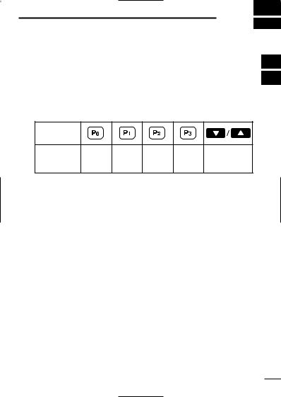
wIf the transceiver is programmed for a start up passcode, input digit codes as directed by your dealer.
•The keys in the table below can be used for password input:
•The transceiver detects numbers in the same block as identical. Therefore “01234” and “56789” are the same.
2
3
KEY |
|
|
|
|
|
|
NUMBER |
0 |
1 |
2 |
3 |
4 |
|
5 |
6 |
7 |
8 |
9 |
||
|
eWhen the “PASSWORD” indication does not clear after inputting 4 digits, the input code number may be incorrect. Turn the power off and start over in this case.
■ Channel selection
Several types of channel selections are available. Methods may differ according to your system set up.
NON-BANK TYPE:
Push [ ]/[
]/[ ] to select the desired operating channel, in sequence; or, push one of the [MR-CH 1] to [MR-CH 4] keys to select a channel directly.
BANK-TYPE:
Push [Bank], then push [ ] or [
 ] to select the desired bank.
AUTOMATIC SCAN TYPE:
Channel setting is not necessary for this type. When turning the power ON, the transceiver automatically starts scanning. Scanning stops when receiving a call.
12
 Loading...