


 Loading...
PT530 500Mbps Powerline Access Point
User Guide

PT530 500Mbps Powerline Access Point
V100R001
User Guide
202595_01
Huawei Technologies Co., Ltd. provides customers with comprehensive technical support and service. Please feel free to contact our local office or company headquarters.
Huawei Technologies Co., Ltd.
Address: Huawei Industrial Base
Bantian, Longgang
Shenzhen 518129
People's Republic of China
Website: http://www.huawei.com
Email: mobile@huawei.com
Contents
1 |
Product Description ........................................................................... |
1 |
|
|
1.1 |
Product Overview ................................................................................. |
1 |
|
1.2 |
Feature Overview.................................................................................. |
1 |
|
1.3 |
Technical Specifications ........................................................................ |
2 |
2 |
Hardware Description ........................................................................ |
4 |
|
|
2.1 |
Ports and Buttons ................................................................................. |
4 |
|
2.2 |
Indicators ............................................................................................. |
7 |
3 |
Quick Setup ....................................................................................... |
9 |
|
|
3.1 |
Pairing Powerline Devices...................................................................... |
9 |
|
3.2 |
Connecting Cables.............................................................................. |
10 |
|
3.3 |
Setting the Computer ......................................................................... |
11 |
|
3.4 |
Setting the PT530 ............................................................................... |
16 |
4 |
Advanced Configuration Guide ........................................................ |
22 |
|
|
4.1 |
Logging In to the Web Management Page .......................................... |
22 |
|
4.2 |
Setting Network Access Parameters .................................................... |
23 |
|
4.3 |
WLAN Configuration .......................................................................... |
26 |
|
4.3.1 Enabling and Disabling the WLAN on the PT530......................... |
26 |
|
|
4.3.2 Changing Your WLAN Name and Password ................................ |
27 |
|
|
4.4 |
Powerline Network Configuration ....................................................... |
27 |
|
4.4.1 Configuring the PLC Network Name........................................... |
27 |
|
|
4.4.2 Adding Powerline Devices to the local PLC network.................... |
28 |
|
|
4.5 |
Network Security ................................................................................ |
29 |
i
|
4.5.1 Hiding the WLAN Name ............................................................. |
29 |
|
|
4.5.2 Using High Security Encryption Modes........................................ |
30 |
|
|
4.5.3 Allowing Only Specified Computers to Access Your WLAN.......... |
31 |
|
|
4.5.4 Controlling Computer Internet Access ........................................ |
32 |
|
|
4.5.5 Filtering Out Inappropriate Websites .......................................... |
33 |
|
|
4.5.6 Preventing Network Attacks ....................................................... |
34 |
|
5 |
Maintenance Guide.......................................................................... |
36 |
|
|
5.1 |
Changing the Web Management Page User Name and Password........ |
36 |
|
5.2 |
Changing the IP Address Used to Log In to the Web Management Page |
|
|
................................................................................................................ |
|
37 |
|
5.3 |
Restoring Default Settings................................................................... |
38 |
|
5.3.1 Using the Configuration Tool...................................................... |
38 |
|
|
5.3.2 Using the Reset Button............................................................... |
39 |
|
|
5.4 |
Upgrading Firmware........................................................................... |
40 |
6 |
Reference Operations....................................................................... |
41 |
|
|
6.1 |
Setting the Computer IP Address......................................................... |
41 |
|
6.2 |
Wireless Connection Setup ................................................................. |
44 |
|
6.2.1 Manually Setting Up a Wireless Connection................................ |
44 |
|
|
6.2.2 Setting Up a Wireless Connection Using the WPS Button ............ |
46 |
|
|
6.3 |
Enabling Wireless Configuration on Windows ..................................... |
47 |
|
6.4 |
Checking the Computer MAC Address ................................................ |
48 |
7 |
FAQs ................................................................................................ |
51 |
|
|
7.1 |
What Can I Do If the PWR Indicator Is Off? ......................................... |
51 |
|
7.2 |
What Can I Do If the LAN Indicator Is Off? .......................................... |
51 |
|
7.3 |
What Can I Do If the PLC Indicator Is Off? ........................................... |
51 |
ii
|
7.4 |
What Can I Do If I Cannot Open the Web Management Page? |
............52 |
|
7.5 |
What Can I Do If I Cannot Access the Internet when I pair one PT530 in |
|
|
router mode with another PT530 in bridge mode? .................................... |
52 |
|
|
7.6 |
Can I Connect Multiple PT530 Adapters .............................................. |
52 |
8 |
Default Settings ............................................................................... |
53 |
|
9 |
For More Help.................................................................................. |
54 |
|
10 |
Legal Notice..................................................................................... |
55 |
|
iii

1 Product Description
1.1 Product Overview
The PT530 500Mbps Powerline Access Point is a data networking device providing data connections for home networks with blazing connection speeds of up to 500 Mbit/s. Adopting Dynamic Neighbor Network Mitigation technology, the PT530 supports stable HD multimedia streaming, online gaming, and Internet surfing. The PT530 uses the existing electrical wiring to connect your HD set top boxes (STBs), PCs, and other devices to your home network and the Internet, eliminating the need to route dedicated network cables. With its support for 802.11n, the PT530 provides network access for mobile phones and tablets at speeds up to 300 Mbit/s.
A secure powerline data connection can be promptly set up with one press of the push- and-pair button.
The PT530 adopts green technology that complies with European Code of Conduct (CoC) on Energy Efficiency and the European Union's Energy-related Products (ErP) Tier 2.
1.2 Feature Overview
High-speed powerline communications
After you plug two or more PT530s (also compatible with PT500s) into power outlets and connect one of the PT530s to a wireless router, you will witness faster and instant access connections and greater Wi-Fi coverage with 500 Mbit/s physical data rate. The PT530 supports HomePlug AV and operates between 1.8 MHz to 68 MHz.
High-speed wireless access
Incredibly fast wireless access with superb signal strength and high data rates of up to 300 Mbit/s is all within your reach as the PT530 supports 2.4 GHz WLAN, adopts MIMO technology, and incorporates 2T2R antennas.
1

Push-and-pair button and WPS button
The PT530 provides two buttons, the push-and-pair button and WPS button, for secure and convenient data network setup.
By pressing the push-and-pair button, you can set up secure powerline data connections between the PT530 and other powerline devices.
By pressing the WPS buttons on the PT530 and any WPS-capable device, you can set up an encrypted data connection.
Easy Configuration and Management
The PT530 provides password-protected web-based management pages to protect your personal data.
1.3 Technical Specifications
Interfaces
1 x AC power plug (powerline communication interface)
2 x 2.4 G built-in antennas (wireless communication interface)
2 x RJ45 10/100M Ethernet ports
5 x LED indicators: PWR (power status), LAN1 (network connection status), LAN2 (network connection status), PLC (pair status), and WLAN (wireless connection status)
4 x buttons: reset button, push-and-pair button, WPS button, and power button
Wireless Functions
Wireless connection control (enable/disable)
SSID configuration
Channels: channels 1 through 13 and the automatic channel
Bandwidths: 20 MHz, 40 MHz, and auto
Wi-Fi modes: 802.11b, 802.11g, 802.11n, 802.11b/g, and 802.11b/g/n
2

Wi-Fi encryption modes: WEP (64/128 bits), TKIP, AES, WPA-PSK, WPA2-PSK, PA- PSK/WPA2-PSK, and MAC address filtering
WPS-capable
Networking and Bridging
Bridging for data forwarding between the powerline and Ethernet
Maintenance and Management
Web-based local management and upgrade
Web-based management interface for easy switching between router mode and bridge mode
Power Supply Specifications
Power supply: 100–240 V AC, 50/60 Hz
Power consumption: < 6 W
Environmental Specifications
Operating temperature: 0°C to 40°C (32°F to 104°F)
Operating humidity: 5% to 95% RH (non-condensing)
Dimensions and Weight
Standard |
Dimensions |
Weight |
|
|
|
|
|
American |
107 mm x 62 mm x 72 mm (4.21 in. x 2.44 |
About 196.2 g |
|
|
in. x 2.83 in.) |
|
|
|
|
|
|
European |
107 mm x 62 mm x 86 mm (4.21 in. x 2.44 |
About 199.8 g |
|
|
in. x 3.39 in.) |
|
|
|
|
|
3
2 Hardware Description
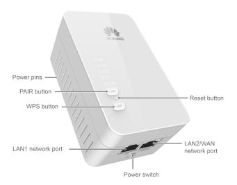
2.1 Ports and Buttons
4
Item |
Description |
||
|
|
||
PAIR |
Pair/Exit button |
||
|
|
Pair: |
|
|
Used to establish connection between two powerline devices. |
||
|
Press and hold this button for about 1 second (from 0.5 second |
||
|
to 4 seconds), and then release it. The PLC indicator will start |
||
|
to blink. Within 2 minutes, press the PAIR button on the other |
||
|
powerline device. If PLC indicators on both two powerline |
||
|
devices turn to steady on from blinking status, it indicates that |
||
|
connection between the PT530 and the PT500 has been |
||
|
established successfully. |
||
|
|
Exit the paring: |
|
|
Used to exit the current pairing connection and prepare for a |
||
|
new connection with other powerline device. Press and hold |
||
|
this button for more than 8 seconds until the PWR indicator |
||
|
turns off and then release it. The PT530 will exit the pairing |
||
|
connection. |
||
5
Item |
Description |
|
|
|
|
WPS |
WPS/WLAN button |
|
|
WPS: |
|
|
Starts Wi-Fi protected setup (WPS) negotiation. |
|
|
Press and hold PT530's WPS button for about 1 second (from |
|
|
0.5 second to 3 seconds), and release it. The WLAN indicator |
|
|
will start to blink. Within 2 minutes, press the WPS button on |
|
|
the wireless terminal such as a Laptop computer. If the WLAN |
|
|
indicator on the PT530 turns to steady on from blinking status, |
|
|
it indicates that wireless connection between wireless terminal |
|
|
and the PT530 has been established successfully. |
|
|
WLAN: |
|
|
Enables or disables the WLAN function. |
|
|
Press and hold this button for more than 3 seconds until the |
|
|
WLAN indicator turns to steady on to enablePT530's wireless |
|
|
network function. Or press and hold this button for more than |
|
|
3 seconds until the WLAN indicator turns off to disable the |
|
|
wireless network function. |
|
LAN1 |
Connects to Ethernet devices, such as computers, set-top boxes |
|
|
(STBs), and switches. |
|
LAN2/WAN |
LAN interface in bridge mode or router mode using |
|
|
powerline uplink: |
|
|
Connects to Ethernet devices, such as computers, set-top boxes |
|
|
(STBs), and switches. |
|
|
WAN interface in router mode using LAN uplink: |
|
|
Connects to an Ethernet device that provides Internet access, |
|
|
such as a modem or switch. |
|
On/Off |
Powers the PT530 on or off. |
6
Item |
Description |
|
|
|
|
Reset |
Used to restore the PT530 to its default settings. |
|
|
After powering on the PT530, please use a needle to press and |
|
|
hold this button for more than 2 seconds until all the indicators |
|
|
turn off. The PT530 will restore to its default settings. |
|
|
CAUTION |
|
|
A reset will result in all custom data and settings being lost. Use |
|
|
with caution. |
|
|
|
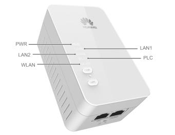
2.2 Indicators
Indicator |
Status |
Description |
|
|
|
|
|
PWR |
Steady on |
The PT530 is powered on. |
|
|
Off |
The PT530 is powered off. |
|
|
|
|
7
Indicator |
Status |
Description |
||
|
|
|
||
LAN1/LAN2 |
Steady on |
The LAN port is connected to an Ethernet |
||
|
|
device (such as a computer) with a network |
||
|
|
cable. |
||
|
Off |
The LAN port is not connected to any |
||
|
|
Ethernet device. |
||
PLC |
Steady on |
The PT530 is connected to a powerline |
||
|
|
device. |
||
|
|
|
||
|
Blinking |
The PT530 is searching for available |
||
|
|
networks. |
||
|
Off |
|
The PT530 is not paired with other |
|
|
|
|
powerline device. |
|
|
|
|
The PT530 is paired but cannot find the |
|
|
|
|
other powerline device. |
|
|
|
|
||
WLAN |
Steady on |
WLAN is enabled. |
||
|
Blinking |
The PT530 is attempting to connect to a |
||
|
|
wireless client over the WLAN using the WPS |
||
|
|
function. |
||
|
|
|
||
|
Off |
WLAN is disabled. |
||
|
|
|
|
|
8

3 Quick Setup
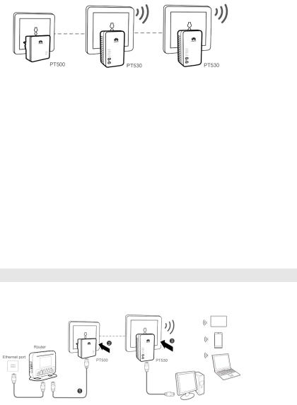
3.1 Pairing Powerline Devices
This product must be used with other powerline devices. This section uses a PT530 and a PT500 to illustrate the pairing process.
1.Plug the PT530 into a power outlet. When the PT530 is powered on, its PWR indicator will turns to steady on.
2.Plug the PT500 into a power outlet nearby the PT530.
3.Press and hold the PAIR button on the PT530 for 1 second and then release it. Its PLC indicator will start to blink.
4.Within 2 minutes, press and hold the PAIR button on the PT500 for 1 second and then release it.
5.Check the indicators' status on the PT530 and the PT500. If both two PLC indicators on the PT530 and the PT500 turn to steady on from blinking status within 10 seconds, the connection between the PT530 and the PT500 has been established successfully.
Leaving an Existing Powerline Network
If you press the PAIR button and the PLC indicator starts to blink while connection cannot be established, press and hold the PAIR button for 8 seconds until the PWR indicator turns off, and then the PT530 will exit the current network. Please repeat the pairing steps to restart the pairing process.
Joining an Existing Powerline Network
If you have another PT530 needs to join the existing powerline network created by the PT530 and the PT500, follow the below steps:
9
1.Press and hold the PAIR button on the newly added PT530 for 1 second, and then release it.
2.Within 2 minutes, press and hold the PAIR button on either the PT530 or the PT500 in the existing powerline network, and then release it.
3.Check the indicators' status on the PT530. When the PLC indicator on the newly added PT530 turns to steady on from blinking status, it indicates that the PT530 is connected to the network.
4.If you have more PT530s need to join this network, please repeat the above operation.
3.2 Connecting Cables
Before you install the PT530, please first make sure that your PC can successfully access the Internet via the Router. Then connect the powerline devices following the instructions below.
Bridge Mode
The PT530's default working mode is bridge. If you already have a router, you can choose this scenario, and then the PT530 will access the Internet through the router.
10
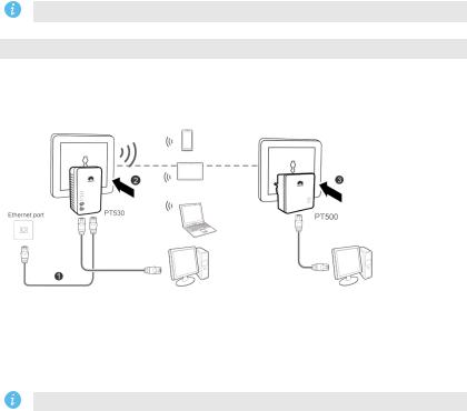
1.Connect one end of a network cable to the PT500. Connect the other end of the same network cable to the router's LAN port.
2.Plug the PT500 into a power outlet.
3.Plug the PT530 into a power outlet.
Please check that the PT530 and the PT500 have been paired.
Router Mode
The PT530 supports router function. You can log in to the web-based configuration utility and set one PT530 to router mode. And the PT530 can be used as a powerline device with wireless router function. If you do not have a router, you can choose this scenario.
1.Connect one end of a network cable to the PT530's LAN2/WAN port. Connect the other end of the same network cable to the Ethernet port on the wall.
2.Plug the PT530 into a power outlet.
3.Plug the PT500 into a power outlet.
Please check that the PT530 and the PT500 have been paired.
3.3 Setting the Computer
Before logging in to the PT530 web management page, set the IP address of the computer that will be used for the login. The PT530's default IP address is 192.168.33.1, and default subnet mask is 255.255.255.0. These values can be changed according to actual needs. This
11
section will take the Windows 7 operating system as an example, to describe how to configure the computer.
Wired Connection
1.Use a network cable to connect the PT530’s LAN1 port and the computer’s network port.
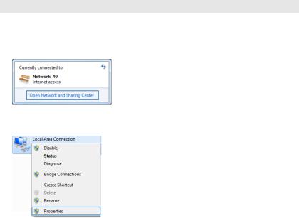
2.Click  in the lower right corner of your desktop, and choose Open Network and Sharing Center.
3.Choose Change adapter settings. Right-click Local Area Connection and choose Properties.
4. Double-click Internet Protocol Version 4 (TCP/IPv4).
12

5.Select Use the following IP address. Set IP address to 192.168.33.100, Subnet mask to 255.255.255.0, and Default gateway to 192.168.33.1. Click OK to return to the previous dialog box and click OK.
13
Wireless Connection
Before setting up a wireless connection, record the WLAN name and password of the PT530. The default WLAN name and password are printed on the PT530 cover label.
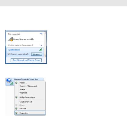
1.Click  in the lower right corner of your desktop. Choose Open Network and Sharing Center.
2.Choose Change adapter settings. Right-click Wireless Network Connection and choose Properties.
3. Double-click Internet Protocol Version 4 (TCP/IPv4).
14
Loading...