


Airbridge DBS3900 CDMA Base Station
V400R006C08
Product Description
Issue 11
Date 2010-06-18
HUAWEI TECHNOLOGIES CO., LTD.

Copyright © Huawei Technologies Co., Ltd. 2010. All rights reserved.
No part of this document may be reproduced or transmitted in any form or by any means without prior written consent of Huawei Technologies Co., Ltd.
Trademarks and Permissions
 and other Huawei trademarks are trademarks of Huawei Technologies Co., Ltd.
All other trademarks and trade names mentioned in this document are the property of their respective holders.
Notice
The purchased products, services and features are stipulated by the contract made between Huawei and the customer. All or part of the products, services and features described in this document may not be within the purchase scope or the usage scope. Unless otherwise specified in the contract, all statements, information, and recommendations in this document are provided "AS IS" without warranties, guarantees or representations of any kind, either express or implied.
The information in this document is subject to change without notice. Every effort has been made in the preparation of this document to ensure accuracy of the contents, but all statements, information, and recommendations in this document do not constitute the warranty of any kind, express or implied.
Huawei Technologies Co., Ltd.
Address: Huawei Industrial Base
Bantian, Longgang
Shenzhen 518129
People's Republic of China
Website: http://www.huawei.com
Email: support@huawei.com
Issue 11 (2010-06-18) |
Huawei Proprietary and Confidential |
i |
|
Copyright © Huawei Technologies Co., Ltd. |
|||
|
|

Airbridge DBS3900 CDMA Base Station |
|
Product Description |
About This Document |
About This Document
Purpose
This document describes the overall structure, logical structure, auxiliary devices, configuration principles, and networking modes of the DBS3900. In addition, this document describes the transmit and receive performance, physical and electrical specifications, lightning protection performance, and environmental requirements of the DBS3900. You can obtain a comprehensive understanding of the DBS3900 by reading this document.
Product Version
The following table lists the product version related to this document.
Product Name |
Product Version |
|
|
DBS3900 CDMA |
V400R006C08 |
|
|
Intended Audience
This document is intended for:
zField engineers
zSystem engineers
Change History
|
Version |
|
Change History |
|
|
|
|
|
|
|
11 (2010-06-18) |
|
The modifications in this version are as |
|
|
|
|
follows: |
|
|
|
|
z Product version update. |
|
|
10 (2010-03-18) |
|
The modifications in this version are as |
|
|
|
|
follows: |
|
|
|
|
z Product version update. |
|
|
|
|
|
|
Issue 11 (2010-06-18) |
Huawei Proprietary and Confidential |
iii |
||
Copyright © Huawei Technologies Co., Ltd.
|
|
Airbridge DBS3900 CDMA Base Station |
About This Document |
Product Description |
|
|
|
|
|
Version |
Change History |
|
|
|
|
09 (2009-12-25) |
Ninth release of the DBS3900 V400R006. |
|
|
|
|
08 (2009-09-15) |
The modifications in this version are as |
|
|
follows: |
|
|
z The contents related to the AWS band |
|
|
classes supported by the AC RRU3606 |
|
|
are added. |
|
|
|
|
07 (2009-08-30) |
Seventh release of the DBS3900 V400R006. |
|
|
|
|
06 (2009-08-15) |
Sixth release of the DBS3900 V400R006. |
|
|
|
|
05 (2009-07-07) |
Fifty release of the DBS3900 V400R006. |
|
|
|
|
04 (2009-05-30) |
The modifications in this version are as |
|
|
follows: |
|
|
z The descriptions of the UBRI and UEIU |
|
|
are added. |
|
|
|
|
03 (2009-04-01) |
The modifications in this version are as |
|
|
follows: |
|
|
z The contents related to the AC RRU3606 |
|
|
are added. |
|
|
z The contents related to the CMPT (8 E1) |
|
|
are added. |
|
|
z The contents related to the 450 MHz band |
|
|
classes supported by the DC RRU3606 |
|
|
are added. |
|
|
|
|
02 (2008-08-10) |
The modifications in this version are as |
|
|
follows: |
|
|
z The networking of the DBS3900 is |
|
|
deleted, and the transmission and |
|
|
networking of the BTS are added. |
|
|
z The contents related to the operation and |
|
|
maintenance of the BTS are modified. |
|
|
z The performance measurement items of |
|
|
the DBS3900 are modified. |
|
|
|
|
01(2008-06-25) |
Initial release of the DBS3900 V400R006. |
|
|
|
Organization
1 Overall Structure of the DBS3900
This describes the overall structure of the DBS3900, which consists of the BBU3900,
RRU3606, cables, antenna system, and auxiliary equipment.
2 Solutions for the Auxiliary Devices of the DBS3900
iv |
Huawei Proprietary and Confidential |
Issue 11 (2010-06-18) |
|
Copyright © Huawei Technologies Co., Ltd. |
|

Airbridge DBS3900 CDMA Base Station |
|
Product Description |
About This Document |
This describes the solutions for the auxiliary devices of the DBS3900. The DBS3900 uses a modular structure. The basic modules of the DBS3900 are the BBU3900 and RRU3606. The auxiliary devices of the DBS3900 include the indoor centralized installation rack, L-shaped support, APM, storage battery cabinet, DCDU, EMUA, SLPU, ODF, DDF, DC power system, and AC power system. The basic modules and auxiliary devices can be flexibly configured to form integrated site solutions.
3 Configuration Principles of the DBS3900
This describes the configuration principles of the DBS3900, covering the configurations of the BBU3900, RRU3606, power supply, and satellite synchronization antenna.
4 Transmission and Networking of the BTS
This describes the transmission and networking of the BTS. The networking modes supported by the BTS are the star networking mode, chain networking mode, and tree networking mode.
5 Operation and Maintenance of the BTS
This section describes the operation and maintenance of the BTS. The operation and maintenance of the BTS refers to the management, monitoring, and maintenance of the BTS. The BTS provides various methods and platforms for operation and maintenance to cater to different scenarios.
6 Technical Specifications of the DBS3900
This describes the technical specifications of the DBS3900.
Conventions
Symbol Conventions
The symbols that may be found in this document are defined as follows.
Symbol |
Description |
|
|
|
Indicates a hazard with a high level of risk that, if not avoided, |
|
will result in death or serious injury. |
|
|
|
Indicates a hazard with a medium or low level of risk which, if |
|
not avoided, could result in minor or moderate injury. |
|
|
|
Indicates a potentially hazardous situation that, if not avoided, |
|
could cause equipment damage, data loss, and performance |
|
degradation, or unexpected results. |
|
|
|
Indicates a tip that may help you solve a problem or save time. |
|
|
|
Provides additional information to emphasize or supplement |
|
important points of the main text. |
|
|
Issue 11 (2010-06-18) |
Huawei Proprietary and Confidential |
v |
|
Copyright © Huawei Technologies Co., Ltd. |
|
|
Airbridge DBS3900 CDMA Base Station |
About This Document |
Product Description |
General Conventions
|
Convention |
|
|
Description |
|
|
|
|
|
||
|
|
|
|
|
|
|
Times New Roman |
Normal paragraphs are in Times New Roman. |
|||
|
|
|
|
||
|
Boldface |
|
Names of files, directories, folders, and users are in |
||
|
|
|
|
boldface. For example, log in as user root. |
|
|
|
|
|
||
|
Italic |
|
Book titles are in italics. |
||
|
|
|
|
||
|
Courier New |
|
Terminal display is in Courier New. |
||
Command Conventions
Convention |
Description |
|
|
Boldface |
The keywords of a command line are in boldface. |
|
|
Italic |
Command arguments are in italics. |
|
|
[ ] |
Items (keywords or arguments) in square brackets [ ] are |
|
optional. |
|
|
{ x | y | ... } |
Alternative items are grouped in braces and separated by |
|
vertical bars. One is selected. |
|
|
[ x | y | ... ] |
Optional alternative items are grouped in square brackets |
|
and separated by vertical bars. One or none is selected. |
|
|
{ x | y | ... } * |
Alternative items are grouped in braces and separated by |
|
vertical bars. A minimum of one or a maximum of all can |
|
be selected. |
|
|
GUI Conventions
Convention |
Description |
|
|
Boldface |
Buttons, menus, parameters, tabs, windows, and dialog titles |
|
are in boldface. For example, click OK. |
|
|
> |
Multi-level menus are in boldface and separated by the ">" |
|
signs. For example, choose File > Create > Folder. |
|
|
Keyboard Operation
Format |
Description |
|
|
Key |
Press the key. For example, press Enter and press Tab. |
|
|
vi |
Huawei Proprietary and Confidential |
Issue 11 (2010-06-18) |
|
Copyright © Huawei Technologies Co., Ltd. |
|
Airbridge DBS3900 CDMA Base Station |
|
|
Product Description |
About This Document |
|
|
|
|
|
Format |
Description |
|
|
|
|
Key 1+Key 2 |
Press the keys concurrently. For example, pressing |
|
|
Ctrl+Alt+A means the three keys should be pressed |
|
|
concurrently. |
|
|
|
|
Key 1, Key 2 |
Press the keys in turn. For example, pressing Alt, A means |
|
|
the two keys should be pressed in turn. |
|
|
|
Mouse Operation
Action |
Description |
|
|
Click |
Select and release the primary mouse button without |
|
moving the pointer. |
|
|
Double-click |
Press the primary mouse button twice continuously and |
|
quickly without moving the pointer. |
|
|
Drag |
Press and hold the primary mouse button and move the |
|
pointer to a certain position. |
|
|
Issue 11 (2010-06-18) |
Huawei Proprietary and Confidential |
vii |
|
Copyright © Huawei Technologies Co., Ltd. |
|

Airbridge DBS3900 CDMA Base Station |
|
Product Description |
Contents |
|
|
|
|
Contents |
|
About This Document................................................................................................................... |
|
iii |
|
|
1 Overall Structure of the DBS3900........................................................................................... |
1-1 |
||
|
1.1 |
Physical Structure of the DBS3900............................................................................................................... |
1-3 |
|
|
1.2 |
Physical Ports of the DBS3900 ..................................................................................................................... |
1-6 |
|
|
|
1.2.1 Ports on the BBU3900 ......................................................................................................................... |
|
1-6 |
|
|
1.2.2 Physical Ports of the RRU3606.......................................................................................................... |
1-10 |
|
|
1.3 |
Logical Structure of the DBS3900 .............................................................................................................. |
1-12 |
|
|
|
1.3.1 Functional Structure of the BBU3900................................................................................................ |
1-12 |
|
|
|
1.3.2 Logical Structure of the RRU3606..................................................................................................... |
1-13 |
|
|
1.4 |
Software Structure of the BTS |
.................................................................................................................... |
1-13 |
|
2 Solutions for the Auxiliary Devices of the DBS3900 .......................................................... |
2-1 |
||
|
2.1 |
Indoor Centralized Installation of the DBS3900 ........................................................................................... |
2-2 |
|
|
2.2 |
Indoor Distributed Installation of the DBS3900............................................................................................ |
2-3 |
|
|
2.3 |
Outdoor Centralized Installation of the DBS3900 ........................................................................................ |
2-4 |
|
|
2.4 |
Outdoor Distributed Installation of the DBS3900......................................................................................... |
2-6 |
|
|
3 Configuration Principles of the DBS3900 ............................................................................. |
3-1 |
||
|
3.1 |
Configuration Principles of the BBU3900 .................................................................................................... |
3-1 |
|
|
3.2 |
Configuration Principles of the RRU3606 .................................................................................................... |
3-3 |
|
|
3.3 |
Configuration Principles of the Power Supply.............................................................................................. |
3-3 |
|
|
3.4 |
Configuration Requirements of the RF Antennas.......................................................................................... |
3-4 |
|
|
3.5 |
Configuration Principles of the Satellite Synchronization Antenna .............................................................. |
3-4 |
|
|
3.6 Typical Configurations of the DBS3900 ....................................................................................................... |
3-5 |
||
|
4 Transmission and Networking of the BTS ........................................................................... |
4-1 |
||
|
4.1 |
Star Networking Mode .................................................................................................................................. |
|
4-1 |
|
4.2 |
Chain Networking Mode............................................................................................................................... |
|
4-2 |
|
4.3 Tree Networking Mode ................................................................................................................................. |
|
4-3 |
|
|
5 Operation and Maintenance of the BTS................................................................................ |
5-1 |
||
|
5.1 |
Operation and Maintenance Modes of the BTS ............................................................................................ |
5-1 |
|
|
5.2 |
Operation and Maintenance Functions of the BTS ....................................................................................... |
5-2 |
|
|
6 Technical Specifications of the DBS3900 .............................................................................. |
6-1 |
||
|
|
|
|
|
|
Issue 11 (2010-06-18) |
Huawei Proprietary and Confidential |
ix |
|
|
|
Copyright © Huawei Technologies Co., Ltd. |
|
|
|
Airbridge DBS3900 CDMA Base Station |
|
Contents |
|
Product Description |
6.1 |
Performance Specifications of the DBS3900 ................................................................................................ |
6-1 |
6.2 |
Physical and Electrical Specifications of the DBS3900................................................................................ |
6-6 |
|
6.2.1 Technical Specifications of the BBU3900 ........................................................................................... |
6-6 |
|
6.2.2 Technical Specifications of the RRU3606 ........................................................................................... |
6-7 |
6.3 |
Reliability Specifications of the DBS3900.................................................................................................... |
6-9 |
6.4 |
Lightning Protection Specifications of the DBS3900 ................................................................................... |
6-9 |
6.5 |
Safety Specifications of the DBS3900 ........................................................................................................ |
6-10 |
6.6 |
EMC Specifications of the DBS3900.......................................................................................................... |
6-11 |
6.7 |
Environmental Specifications of the DBS3900........................................................................................... |
6-12 |
|
6.7.1 Storage Environment.......................................................................................................................... |
6-12 |
|
6.7.2 Transportation Environment .............................................................................................................. |
6-15 |
|
6.7.3 Requirements for the Running Environment of the DBS3900........................................................... |
6-19 |
x |
Huawei Proprietary and Confidential |
Issue 11 (2010-06-18) |
|
Copyright © Huawei Technologies Co., Ltd. |
|

Airbridge DBS3900 CDMA Base Station |
|
Product Description |
Figures |
Figures
Figure 1-1 Hardware structure of the DBS3900................................................................................................. |
1-1 |
Figure 1-2 Major functional modules of the DBS3900 ...................................................................................... |
1-3 |
Figure 1-3 BBU3900.......................................................................................................................................... |
1-3 |
Figure 1-4 Configuration of the BBU3900......................................................................................................... |
1-3 |
Figure 1-5 DC RRU3606 ................................................................................................................................... |
1-5 |
Figure 1-6 AC RRU3606.................................................................................................................................... |
1-6 |
Figure 1-7 Logical structure of the RRU3606.................................................................................................. |
1-13 |
Figure 1-8 Software structure of the BTS ........................................................................................................ |
1-14 |
Figure 2-1 Indoor Centralized Installation of the DBS3900............................................................................... |
2-2 |
Figure 2-2 Indoor distributed installation........................................................................................................... |
2-4 |
Figure 2-3 Outdoor centralized installation of the DBS3900 ............................................................................. |
2-5 |
Figure 2-4 Outdoor distributed installation of the DBS3900 ............................................................................. |
2-7 |
Figure 4-1 Star networking mode....................................................................................................................... |
4-2 |
Figure 4-2 Chain networking mode.................................................................................................................... |
4-3 |
Figure 4-3 Tree networking mode ...................................................................................................................... |
4-4 |
Figure 5-1 Networking of the operation and maintenance system ..................................................................... |
5-2 |
Figure 6-1 Dimensions of the BBU3900............................................................................................................ |
6-7 |
Issue 11 (2010-06-18) |
Huawei Proprietary and Confidential |
xi |
|
Copyright © Huawei Technologies Co., Ltd. |
|
Airbridge DBS3900 CDMA Base Station |
|
Product Description |
Tables |
Tables
Table 1-1 Boards in the BBU3900...................................................................................................................... |
1-4 |
Table 1-2 Ports on the RRU3606 (DC type)..................................................................................................... |
1-10 |
Table 1-3 Ports on the RRU3606 (AC type)..................................................................................................... |
1-11 |
Table 2-1 Auxiliary devices used in the door distributed installation of the DBS3900 ...................................... |
2-3 |
Table 2-2 Auxiliary devices used in the door distributed installation of the DBS3900 ...................................... |
2-4 |
Table 2-3 Auxiliary devices used in the outdoor distributed installation of the DBS3900 ................................. |
2-6 |
Table 2-4 Auxiliary devices used in the door distributed installation of the DBS3900 ...................................... |
2-7 |
Table 3-1 Power supply configuration in indoor installation.............................................................................. |
3-3 |
Table 3-2 Power supply configuration in outdoor installation............................................................................ |
3-4 |
Table 6-1 Transmit specifications in band class 0 (800 MHz)............................................................................ |
6-2 |
Table 6-2 Receive specifications in band class 0 (800 MHz) ............................................................................. |
6-2 |
Table 6-3 Transmit specifications in band class 1 (1900 MHz).......................................................................... |
6-2 |
Table 6-4 Receive specifications in band class 1 (1900 MHz) ........................................................................... |
6-3 |
Table 6-5 Transmit specifications in band class 5 (450 MHz)............................................................................ |
6-3 |
Table 6-6 Receive specifications in band class 5 (450 MHz) ............................................................................. |
6-3 |
Table 6-7 Transmit specifications in band class 14 (1900 MHz)........................................................................ |
6-4 |
Table 6-8 Receive specifications in band class 14 (1900 MHz) ......................................................................... |
6-4 |
Table 6-9 Transmit specifications in band class 15 (AWS) ................................................................................ |
6-4 |
Table 6-10 Receive specifications in band class 15 (AWS)................................................................................ |
6-5 |
Table 6-11 RRU3606 cascading specifications of the DBS3900........................................................................ |
6-5 |
Table 6-12 BER threshold specifications of BTS transmission links ................................................................. |
6-6 |
Table 6-13 Technical specifications of the BBU3900......................................................................................... |
6-7 |
Table 6-14 Technical specifications of the RRU3606 (DC type)........................................................................ |
6-7 |
Table 6-15 Technical specifications of the RRU3606 (AC type)........................................................................ |
6-8 |
Table 6-16 Reliability specifications of the DBS3900........................................................................................ |
6-9 |
Table 6-17 Lightning protection specifications of the DBS3900........................................................................ |
6-9 |
Issue 11 (2010-06-18) |
Huawei Proprietary and Confidential |
xiii |
|
Copyright © Huawei Technologies Co., Ltd. |
|
|
Airbridge DBS3900 CDMA Base Station |
|
Tables |
Product Description |
|
|
Table 6-18 Climatic requirements for the storage environment of the equipment............................................ |
6-13 |
|
Table 6-19 Requirements for the concentration of mechanically active substances in the storage environment of |
|
|
the equipment.................................................................................................................................................... |
6-14 |
|
Table 6-20 Requirements for the concentration of chemically active substances in the storage environment of |
|
|
the equipment.................................................................................................................................................... |
6-14 |
|
Table 6-21 Requirements for the mechanical stress in the storage environment of the BBU........................... |
6-15 |
|
Table 6-22 Requirements for the mechanical stress in the storage environment of the RRU........................... |
6-15 |
|
Table 6-23 Climatic requirements for the transportation environment of the equipment ................................. |
6-16 |
|
Table 6-24 Requirements for the concentration of mechanically active substances in the transportation |
|
|
environment of the equipment........................................................................................................................... |
6-17 |
|
Table 6-25 Requirements for the concentration of chemically active substances in the transportation |
|
|
environment of the equipment........................................................................................................................... |
6-17 |
|
Table 6-26 Requirements for the mechanical stress in the transportation environment of the BBU ................ |
6-18 |
|
Table 6-27 Requirements for the mechanical stress in the transportation environment of the RRU ................ |
6-18 |
|
Table 6-28 Climatic requirements for the running environment of the equipment........................................... |
6-19 |
|
Table 6-29 Requirements for the concentration of mechanically active substances in the running environment of |
|
|
the equipment.................................................................................................................................................... |
6-20 |
|
Table 6-30 Requirements for the concentration of chemically active substances in the running environment of |
|
|
the BBU............................................................................................................................................................. |
6-20 |
|
Table 6-31 Requirements for the concentration of chemically active substances in the running environment of |
|
|
the RRU............................................................................................................................................................. |
6-20 |
|
Table 6-32 Requirements for the mechanical stress in the running environment of the BBU .......................... |
6-21 |
|
Table 6-33 Requirements for the mechanical stress in the running environment of the RRU .......................... |
6-21 |
xiv |
Huawei Proprietary and Confidential |
Issue 11 (2010-06-18) |
|
Copyright © Huawei Technologies Co., Ltd. |
|
Airbridge DBS3900 CDMA Base Station |
|
Product Description |
1 Overall Structure of the DBS3900 |
1 Overall Structure of the DBS3900
About This Chapter
This describes the overall structure of the DBS3900, which consists of the BBU3900,
RRU3606, cables, antenna system, and auxiliary equipment.
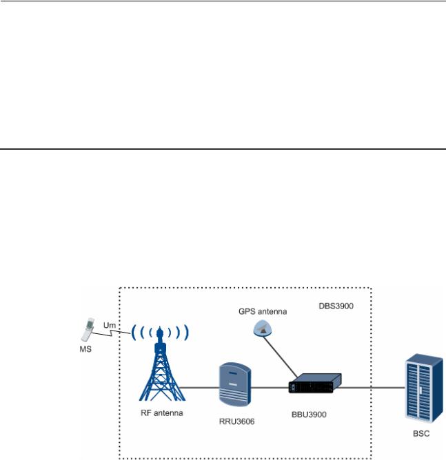
Figure 1-1 shows the hardware structure of the DBS3900.
Figure 1-1 Hardware structure of the DBS3900
Functional Modules of the DBS3900
|
Functional |
|
Description |
|
|
Module |
|
|
|
|
|
|
|
|
|
BBU3900 |
|
Being the baseband unit of the DBS3900, this component is responsible |
|
|
|
|
for resource management, operation and maintenance, and environment |
|
|
|
|
monitoring of the system. |
|
|
|
|
|
|
|
RRU3606 |
|
Being the remote RF module unit of the DBS3900, this component is |
|
|
|
|
responsible for transmitting and receiving radio signals to achieve |
|
|
|
|
communications between the wireless network system and the MSs. |
|
|
|
|
|
|
|
|
|
|
|
Issue 11 (2010-06-18) |
Huawei Proprietary and Confidential |
1-1 |
||
|
|
Copyright © Huawei Technologies Co., Ltd. |
|
|

|
Airbridge DBS3900 CDMA Base Station |
1 Overall Structure of the DBS3900 |
Product Description |
There are two types of RRU3606s. One type uses DC power supply whereas the other type uses AC power supply.
The band classes that the DC RRU3606 and AC RRU3606 support are as follows:
zThe DC RRU3606 supports the 450 MHz, 800 MHz, 1900 MHz, and AWS band classes.
zThe AC RRU3606 supports the 800 MHz A and AWS band classes.
Composition of the DBS3900
Device |
Description |
|
|
APM30 |
The APM30 is an integrated power system for outdoor use and |
|
has the following features: |
|
z Supporting -48 V DC and 110/220 V AC power supply |
|
z Providing at most 12 U space for user equipment when not |
|
configured with additional devices |
|
z Supporting internal storage batteries in the case of AC input |
|
z Supporting piled installation with the storage battery cabinet |
|
(under the APM30 cabinet), which is optional |
|
|
DCDU |
The DCDU is a power distribution box and supports one DC |
|
input and nine DC outputs. |
|
|
EMUA |
The EMUA is an environment monitoring unit and implements |
|
monitoring for the site environment and user equipment. |
|
For details on the functions of the EMUA, see the EMUA User |
|
Guide. |
|
|
SLPU |
The SLPU is a lightning protection unit, which is used to |
|
configure the UELP and UFLP. It implements lightning |
|
protection for E1/T1 and FE/GE signals. |
|
|
DDF |
DDFs are classified into two types, which are used for coaxial |
|
cables and twisted-pair cables respectively. A DDF is required |
|
when the transmission equipment and BBU3900 are configured |
|
in the same cabinet. |
|
|
DC power system |
Made up of PSUDC/DC modules, the DC power system converts |
|
+24 V DC input to -48 V DC output. |
|
|
AC power system |
Made up of PSUAC/DC modules and PMU modules, the AC |
|
power system converts 220/110 V AC input to -48 V DC |
|
output. |
|
|
1.1Physical Structure of the DBS3900
This describes the physical structure of the DBS3900, which consists of the BBU3900, RRU3606, and auxiliary equipment.
1.2Physical Ports of the DBS3900
This describes the physical ports of the DBS3900.
1-2 |
Huawei Proprietary and Confidential |
Issue 11 (2010-06-18) |
|
Copyright © Huawei Technologies Co., Ltd. |
|
Airbridge DBS3900 CDMA Base Station |
|
Product Description |
1 Overall Structure of the DBS3900 |
1.3Logical Structure of the DBS3900
This describes the logical structure of the DBS3900.
1.4Software Structure of the BTS
This section describes the software structure of the BTS. The BTS software consists of the platform software, signaling protocol software, operation and maintenance software, and data center.
1.1 Physical Structure of the DBS3900
This describes the physical structure of the DBS3900, which consists of the BBU3900,
RRU3606, and auxiliary equipment.
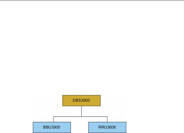
Figure 1-2 shows the major functional modules of the DBS3900.
Figure 1-2 Major functional modules of the DBS3900
Physical Structure of the BBU3900
Figure 1-4 shows the configuration of the BBU3900.
Figure 1-3 Configuration of the BBU3900
|
HCPM/HECM |
|
HCPM/HECM/UTRP/UELP/UFLP |
UPEU/UEIU |
|
|
0 |
|
4 |
|
|
|
|
|
|
||
|
HCPM/HECM/USCU |
|
HCPM/HECM/UTRP/UELP/UFLP/USCU |
0 |
|
|
1 |
|
5 |
|
|
FAN |
|
|
|
||
HCPM/HECM/USCU/LBBP |
|
CMPT/USCU/LMPT |
UPEU |
||
|
|
||||
|
2 |
|
6 |
|
|
|
HCPM/HECM/UBRI |
|
CMPT |
|
1 |
|
|
|
|
|
|
|
3 |
|
7 |
|
|
Issue 11 (2010-06-18) |
Huawei Proprietary and Confidential |
1-3 |
|
Copyright © Huawei Technologies Co., Ltd. |
|
|
|
|
Airbridge DBS3900 CDMA Base Station |
|
1 Overall Structure of the DBS3900 |
|
|
Product Description |
|
|
Table 1-1 Boards in the BBU3900 |
|
|
|
|
|
|
|
|
|
Module |
Expansion |
Description |
Function |
|
|
|
|
|
|
CMPT |
CDMA Main |
It is the main |
It processes and transmits data |
|
|
Processing&Tra |
processing and |
between the BTS and the BSC, |
|
|
nsmission Unit |
transmission |
controls and manages the entire |
|
|
|
module. |
BTS, and provides clock signals |
|
|
|
|
for the BTS system. |
|
|
|
|
|
|
HCPM |
HERT Channel |
It is the 1X |
It processes the 1X service data |
|
|
Processing |
channel |
on forward and reverse channels. |
|
|
Module |
processing |
|
|
|
|
module. |
|
|
|
|
|
|
|
HECM |
HERT Enhance |
It is the EV-DO |
It processes the EV-DO service |
|
|
Channel |
channel |
data on forward and reverse |
|
|
Processing |
processing |
channels. |
|
|
Module |
module. |
|
|
|
|
|
|
|
LMPT |
LTE Main |
It is LTE main |
It manages the entire eNodeB in |
|
|
Processing & |
control and |
terms of OM and signaling |
|
|
Transmission |
transmission unit. |
processing and provides clock |
|
|
Unit |
|
signals for the BBU3900. |
|
|
|
|
|
|
LBBP |
LTE BaseBand |
It is LTE |
It processes the baseband signals |
|
|
Processing unit |
BaseBand |
and Common Public Radio |
|
|
|
Processing unit. |
Interface (CPRI) signals. |
|
|
|
|
|
|
UTRP |
Universal |
It is the universal |
It provides connection between |
|
|
Extension |
extension |
the BBU3900 and the BSC, and |
|
|
Transmission |
transmission |
supports IP transmission over |
|
|
Processing Unit |
processing unit. |
E1/T1 links. |
|
|
|
|
|
|
UBRI |
Universal |
It is the universal |
It implements the functions of PN |
|
|
Baseband Radio |
extension radio |
sharing, 1X resource pool, and |
|
|
Interface Unit |
interface unit. |
convergence and distribution of |
|
|
|
|
baseband data. |
|
|
|
|
|
|
UEIU |
Universal |
It is the universal |
It provides the environment |
|
|
Environment |
environment |
monitoring signal port for the |
|
|
Interface Unit |
interface unit. |
BBU3900. |
|
|
|
|
|
|
UELP |
Universal E1/T1 |
It is the universal |
It provides surge protection for |
|
|
Lightning |
E1/T1 surge |
E1/T1 signals. |
|
|
Protection Unit |
protection unit. |
|
|
|
|
|
|
|
UFLP |
Universal |
It is the FE/GE |
It provides surge protection for |
|
|
FE/GE |
surge protection |
FE signals. |
|
|
Lightning |
unit. |
|
|
|
Protection Unit |
|
|
|
|
|
|
|
|
FAN |
FAN Unit |
It is the FAN unit |
It implements heat dissipation for |
|
|
|
of the BBU3900. |
the BBU3900. |
|
|
|
|
|
1-4 |
Huawei Proprietary and Confidential |
Issue 11 (2010-06-18) |
|
Copyright © Huawei Technologies Co., Ltd. |
|
Airbridge DBS3900 CDMA Base Station |
|
|
||
Product Description |
|
|
1 Overall Structure of the DBS3900 |
|
|
|
|
|
|
|
Module |
Expansion |
Description |
Function |
|
|
|
|
|
|
UPEU |
Universal Power |
It is the universal |
It converts -48 V DC or +24 V |
|
|
and |
power and |
DC to +12 V DC and provides |
|
|
Environment |
environment |
environment monitoring signal |
|
|
Interface Unit |
interface unit. |
ports for the BBU3900. |
|
|
|
|
|
|
USCU |
Universal |
It is the universal |
It provides the input port for |
|
|
Satellite Card |
satellite card and |
external signals (including |
|
|
and Clock Unit |
clock unit. |
satellite clock signals), and |
|
|
|
|
provides synchronization clock |
|
|
|
|
signals for the BBU3900 and for |
|
|
|
|
the RF modules connected to the |
|
|
|
|
BBU3900. |
|
|
|
|
|
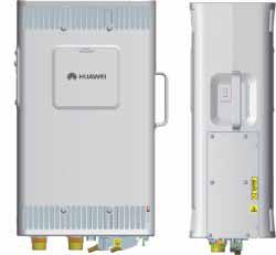
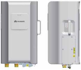
Physical Structure of the RRU3606
The RRU3606 is of two types, that is, the DC RRU3606 and the AC RRU3606, as shown in Figure 1-5 and Figure 1-6.
Figure 1-4 DC RRU3606
Issue 11 (2010-06-18) |
Huawei Proprietary and Confidential |
1-5 |
|
Copyright © Huawei Technologies Co., Ltd. |
|
|
Airbridge DBS3900 CDMA Base Station |
1 Overall Structure of the DBS3900 |
Product Description |
Figure 1-5 AC RRU3606
1.2 Physical Ports of the DBS3900
This describes the physical ports of the DBS3900.
1.2.1Ports on the BBU3900
The ports of the BBU3900 consist of the power ports, transmission ports, alarm ports, reserved ports, and ports connected to other equipment.
1.2.2Physical Ports of the RRU3606
The physical ports of the RRU3606 include power ports, transmission ports, alarm ports, grounding ports, and RF ports. The physical ports of the DC RRU3606 slightly different from those of the AC RRU3606.
1.2.1 Ports on the BBU3900
The ports of the BBU3900 consist of the power ports, transmission ports, alarm ports, reserved ports, and ports connected to other equipment.
Ports on Mandatory Boards
|
Board |
|
|
Port |
|
Quantit |
Connector |
|
Function |
|
|
|
|
|
y |
Type |
|
|
|||
|
|
|
|
|
|
|
|
|
|
|
|
CMPT (4 |
|
E1/T1 |
1 |
DB26 |
It is a transmission port, |
||||
|
E1) |
|
|
|
|
|
|
which is connected to |
||
|
|
|
|
|
|
|
|
|
the BSC and provides |
|
|
|
|
|
|
|
|
|
|
four E1/T1 links. |
|
|
|
|
|
|
|
|
|
|
|
|
1-6 |
Huawei Proprietary and Confidential |
Issue 11 (2010-06-18) |
|
Copyright © Huawei Technologies Co., Ltd. |
|
Airbridge DBS3900 CDMA Base Station |
|
|
|
|
|
|
||||||
Product Description |
|
|
|
|
|
1 Overall Structure of the DBS3900 |
||||||
|
|
|
|
|
|
|
|
|
|
|
|
|
|
|
Board |
|
|
Port |
|
Quantit |
Connector |
|
Function |
|
|
|
|
|
|
|
y |
Type |
|
|
|
|||
|
|
|
|
|
|
|
|
|
|
|
|
|
|
|
|
|
|
FE0 |
1 |
RJ45 |
|
|
It is the transmission |
||
|
|
|
|
|
|
|
|
|
|
|
port, which is connected |
|
|
|
|
|
|
|
|
|
|
|
|
to the BSC and provides |
|
|
|
|
|
|
|
|
|
|
|
|
one FE link. |
|
|
|
|
|
|
|
|
|
|
|
|
FE electrical port, |
|
|
|
|
|
|
|
|
|
|
|
|
supporting cable |
|
|
|
|
|
|
|
|
|
|
|
|
connection |
|
|
|
|
|
|
|
|
|
|
|
|
||
|
|
|
|
|
FE1 |
1 |
SFP |
|
|
It is the transmission |
||
|
|
|
|
|
|
|
|
|
|
|
port, which is connected |
|
|
|
|
|
|
|
|
|
|
|
|
to the BSC and provides |
|
|
|
|
|
|
|
|
|
|
|
|
one FE link. |
|
|
|
|
|
|
|
|
|
|
|
|
FE optical port, |
|
|
|
|
|
|
|
|
|
|
|
|
supporting optical |
|
|
|
|
|
|
|
|
|
|
|
|
cables (a removable |
|
|
|
|
|
|
|
|
|
|
|
|
optical module is |
|
|
|
|
|
|
|
|
|
|
|
|
required) |
|
|
|
|
|
|
|
|
|
|
|
|
||
|
|
|
|
|
USB |
1 |
USB |
|
|
It is reserved. |
||
|
|
|
|
|
|
|
|
|
|
|
||
|
|
|
|
|
TST |
1 |
USB |
|
|
It is a clock test port. |
||
|
|
|
|
|
|
|
|
|
|
|
||
|
|
|
|
|
ETH |
1 |
RJ45 |
|
|
It is a commissioning |
||
|
|
|
|
|
|
|
|
|
|
|
port for local |
|
|
|
|
|
|
|
|
|
|
|
|
maintenance. |
|
|
|
|
|
|
|
|
|
|
|
|
||
|
|
|
|
|
GPS |
1 |
SMA |
|
|
It is used for GPS signal |
||
|
|
|
|
|
|
|
|
|
|
|
input. |
|
|
|
|
|
|
|
|
|
|
||||
|
|
CMPT (8 |
|
E1/T1 |
1 |
DB44 |
|
It is a transmission port, |
||||
|
|
E1) |
|
|
|
|
|
|
|
which is connected to |
||
|
|
|
|
|
|
|
|
|
|
|
the BSC and provides |
|
|
|
|
|
|
|
|
|
|
|
|
eight E1/T1 links. |
|
|
|
|
|
|
|
|
|
|
|
|
||
|
|
|
|
|
FE0 |
1 |
RJ45 |
|
|
It is a transmission port, |
||
|
|
|
|
|
|
|
|
|
|
|
which is connected to |
|
|
|
|
|
|
|
|
|
|
|
|
the BSC and provides |
|
|
|
|
|
|
|
|
|
|
|
|
one FE link. |
|
|
|
|
|
|
|
|
|
|
|
|
It is an FE electrical port |
|
|
|
|
|
|
|
|
|
|
|
|
supporting cable |
|
|
|
|
|
|
|
|
|
|
|
|
connection. |
|
|
|
|
|
|
|
|
|
|
|
|
||
|
|
|
|
|
USB |
1 |
USB |
|
|
It is reserved. |
||
|
|
|
|
|
|
|
|
|
|
|
||
|
|
|
|
|
TST |
1 |
USB |
|
|
It is a clock test port. |
||
|
|
|
|
|
|
|
|
|
|
|
||
|
|
|
|
|
ETH |
1 |
RJ45 |
|
|
It is a commissioning |
||
|
|
|
|
|
|
|
|
|
|
|
port for local |
|
|
|
|
|
|
|
|
|
|
|
|
maintenance. |
|
|
|
|
|
|
|
|
|
|
|
|
||
|
|
|
|
|
GPS |
1 |
SMA |
|
|
It is used for GPS signal |
||
|
|
|
|
|
|
|
|
|
|
|
input. |
|
|
|
|
|
|
|
|
|
|
|
|
|
|
Issue 11 (2010-06-18) |
Huawei Proprietary and Confidential |
1-7 |
|
Copyright © Huawei Technologies Co., Ltd. |
|
|
|
|
|
|
|
|
|
|
|
Airbridge DBS3900 CDMA Base Station |
|||
1 Overall Structure of the DBS3900 |
|
|
|
|
|
|
|
|
Product Description |
||||
|
|
|
|
|
|
|
|
|
|
|
|
|
|
|
|
Board |
|
|
Port |
|
Quantit |
|
|
Connector |
|
Function |
|
|
|
|
|
|
y |
|
|
Type |
|
|
|||
|
|
|
|
|
|
|
|
|
|
|
|
|
|
|
|
HCPM/HEC |
|
SFP |
3 |
|
|
SFP |
|
They are connected to |
|||
|
|
M |
|
|
|
|
|
|
|
|
the RF module. |
||
|
|
|
|
|
|
|
|
|
|
|
|||
|
|
LMPT |
|
SFP 0 and SFP 1 |
2 |
|
|
LC |
|
Indicate Ethernet optical |
|||
|
|
|
|
|
|
|
|
|
|
|
|
ports, which are used to |
|
|
|
|
|
|
|
|
|
|
|
|
|
connect to the |
|
|
|
|
|
|
|
|
|
|
|
|
|
transmission device or |
|
|
|
|
|
|
|
|
|
|
|
|
|
gateway |
|
|
|
|
|
|
|
|
|
|
|
|
|
||
|
|
|
|
|
USB |
1 |
|
|
USB |
|
Loads software to the |
||
|
|
|
|
|
|
|
|
|
|
|
|
board |
|
|
|
|
|
|
|
|
|
|
|
|
|
||
|
|
|
|
|
TST |
1 |
|
|
USB |
|
Test |
||
|
|
|
|
|
|
|
|
|
|
|
|
|
|
|
|
|
|
|
|
|
|
|
|
|
|
||
|
|
|
|
|
ETH |
1 |
|
|
RJ-45 |
|
Debug |
||
|
|
|
|
|
FE/GE0 and |
2 |
|
RJ-45 |
|
Indicate Ethernet |
|||
|
|
|
|
|
FE/GE |
|
|
|
|
|
electrical ports, which |
||
|
|
|
|
|
|
|
|
|
|
|
|
are used for connection |
|
|
|
|
|
|
|
|
|
|
|
|
|
to the transmission |
|
|
|
|
|
|
|
|
|
|
|
|
|
device or gateway |
|
|
|
|
|
|
GPS |
1 |
|
SMA |
|
Receives GPS signals |
|||
|
|
|
|
|
|
|
|
|
|
|
|||
|
|
|
|
|
RST |
1 |
|
- |
|
Resets the BBU3900 |
|||
|
|
|
|
|
|
|
|
|
|
|
|
||
|
|
LBBP |
|
CPRI0 to CPRI5 |
6 |
|
|
SFP connector |
|
Connecting to the |
|||
|
|
|
|
|
|
|
|
|
LRRU, LRFU, |
||||
|
|
|
|
|
|
|
|
|
|
|
|
||
|
|
|
|
|
|
|
|
|
|
|
|
RRU3606 or CRFU for |
|
|
|
|
|
|
|
|
|
|
|
|
|
transmitting service |
|
|
|
|
|
|
|
|
|
|
|
|
|
data, clock signals, and |
|
|
|
|
|
|
|
|
|
|
|
|
|
synchronization |
|
|
|
|
|
|
|
|
|
|
|
|
|
information |
|
|
|
UPEU |
|
Power port |
1 |
|
|
3V3 |
|
It is used for DC input. |
|||
|
|
|
|
|
|
|
|
|
|
|
|||
|
|
|
|
|
MON0 |
1 |
|
RJ45 |
|
Each port provides |
|||
|
|
|
|
|
|
|
|
|
|
|
|
monitoring function for |
|
|
|
|
|
|
MON1 |
1 |
|
RJ45 |
|
||||
|
|
|
|
|
|
|
one RS485 link. There |
||||||
|
|
|
|
|
|
|
|
|
|
|
|
are totally two RS485 |
|
|
|
|
|
|
|
|
|
|
|
|
|
links. |
|
|
|
|
|
|
|
|
|
|
|
|
|
||
|
|
|
|
|
EXT-ALM0 |
1 |
|
|
RJ45 |
|
Each port provides four |
||
|
|
|
|
|
|
|
|
|
|
|
|
links for dry contact |
|
|
|
|
|
|
EXT-ALM1 |
1 |
|
|
RJ45 |
|
|||
|
|
|
|
|
|
|
|
alarm signal input. |
|||||
|
|
|
|
|
|
|
|
|
|
|
|
There are totally eight |
|
|
|
|
|
|
|
|
|
|
|
|
|
links of dry contact |
|
|
|
|
|
|
|
|
|
|
|
|
|
alarm signals. |
|
|
|
|
|
|
|
|
|
|
|
|
|
|
|
1-8 |
Huawei Proprietary and Confidential |
Issue 11 (2010-06-18) |
|
Copyright © Huawei Technologies Co., Ltd. |
|
Airbridge DBS3900 CDMA Base Station |
|
Product Description |
1 Overall Structure of the DBS3900 |
Ports on Optional Boards
|
|
Board |
|
|
Port |
|
|
|
Quantit |
|
|
Connector |
|
|
Function |
|
|
|
|
|
|
|
|
y |
|
|
Type |
|
|
|
|||
|
|
|
|
|
|
|
|
|
|
|
|
|
|
|
|
|
|
|
UELP |
|
|
INSIDE |
|
1 |
|
|
DB25 |
It provides four links for |
|||||
|
|
|
|
|
|
|
|
|
|
|
|
|
|
|
E1/T1 signal input and |
|
|
|
|
|
|
|
|
|
|
|
|
|
|
|
|
is connected to the |
|
|
|
|
|
|
|
|
|
|
|
|
|
|
|
|
BBU. |
|
|
|
|
|
|
|
|
|
|
|
|
||||||
|
|
|
|
|
OUTSIDE |
|
1 |
|
DB26 |
It provides four links for |
||||||
|
|
|
|
|
|
|
|
|
|
|
|
|
|
|
E1/T1 signal output, and |
|
|
|
|
|
|
|
|
|
|
|
|
|
|
|
|
connects the |
|
|
|
|
|
|
|
|
|
|
|
|
|
|
|
|
transmission equipment |
|
|
|
|
|
|
|
|
|
|
|
|
|
|
|
|
and the BSC. |
|
|
|
|
|
|
|
|
|
|
|
|
||||||
|
|
UFLP |
|
|
FE0 and FE1 |
|
2 |
|
RJ45 |
Each port provides one |
||||||
|
|
|
|
|
(INSIDE) |
|
|
|
|
|
|
|
|
link for FE signal input |
||
|
|
|
|
|
|
|
|
|
|
|
|
|
|
|
and is connected to the |
|
|
|
|
|
|
|
|
|
|
|
|
|
|
|
|
BBU. |
|
|
|
|
|
|
|
|
|
|
|
|
||||||
|
|
|
|
|
FE0 and FE1 |
|
2 |
|
RJ45 |
Each port provides four |
||||||
|
|
|
|
|
(OUTSIDE) |
|
|
|
|
|
|
|
|
links for E1/T1 signal |
||
|
|
|
|
|
|
|
|
|
|
|
|
|
|
|
output and connects the |
|
|
|
|
|
|
|
|
|
|
|
|
|
|
|
|
transmission equipment |
|
|
|
|
|
|
|
|
|
|
|
|
|
|
|
|
and the BSC. |
|
|
|
|
|
|
|
|
|
|
|
|
|
|
||||
|
|
USCU0 |
|
|
GPS port |
|
1 |
|
|
SMA |
|
It is used for receiving |
||||
|
|
|
|
|
|
|
|
|
|
|
|
|
|
|
GPS signals. |
|
|
|
|
|
|
|
|
|
|
|
|
|
|
||||
|
|
|
|
|
RGPS port |
|
3 |
|
|
8-pin terminal |
|
They are used for |
||||
|
|
|
|
|
|
|
|
|
|
|
|
block |
|
receiving RGPS signals. |
||
|
|
|
|
|
|
|
|
|
|
|
|
|
||||
|
|
|
|
|
BITS port |
|
1 |
|
|
SMA |
|
It is connected to the |
||||
|
|
|
|
|
|
|
|
|
|
|
|
|
|
|
BITS clock. |
|
|
|
|
|
|
|
|
|
|
|
|
|
|
||||
|
|
|
|
|
TEST port |
|
1 |
|
|
SMA |
|
It is used as the output |
||||
|
|
|
|
|
|
|
|
|
|
|
|
|
|
|
end for the clock test. |
|
|
|
|
|
|
|
|
|
|
|
|
|
|
||||
|
|
USCUb0 |
|
|
GPS port |
|
1 |
|
|
SMA |
|
It is used for receiving |
||||
|
|
|
|
|
|
|
|
|
|
|
|
|
|
|
GPS signals. |
|
|
|
|
|
|
|
|
|
|
|
|
|
|
||||
|
|
|
|
|
RGPS port |
|
2 |
|
|
8-pin terminal |
|
They are used for |
||||
|
|
|
|
|
|
|
|
|
|
|
|
block |
|
receiving RGPS signals. |
||
|
|
|
|
|
|
|
|
|
|
|
||||||
|
|
|
|
|
TOD port |
|
2 |
|
RJ45 |
They are used for |
||||||
|
|
|
|
|
|
|
|
|
|
|
|
|
|
|
receiving or transmitting |
|
|
|
|
|
|
|
|
|
|
|
|
|
|
|
|
1PPS and TOD signals. |
|
|
|
|
|
|
|
|
|
|
|
|
|
|
||||
|
|
|
|
|
BITS port |
|
1 |
|
|
SMA |
|
It is connected to the |
||||
|
|
|
|
|
|
|
|
|
|
|
|
|
|
|
BITS clock and supports |
|
|
|
|
|
|
|
|
|
|
|
|
|
|
|
|
the adaptive input of |
|
|
|
|
|
|
|
|
|
|
|
|
|
|
|
|
2.048 MHz clock |
|
|
|
|
|
|
|
|
|
|
|
|
|
|
|
|
signals and 10 MHz |
|
|
|
|
|
|
|
|
|
|
|
|
|
|
|
|
clock signals. |
|
|
|
|
|
|
|
|
|
|
|
|
|
|
||||
|
|
|
|
|
M-1PPS port |
|
1 |
|
|
SMA |
|
It is used for receiving |
||||
|
|
|
|
|
|
|
|
|
|
|
|
|
|
|
M1000 1PPS signals. |
|
|
|
|
|
|
|
|
|
|
|
|
|
|
|
|
|
|
|
|
|
|
|
|
|
|
|
|
|
|
|
|
|
|
|
Issue 11 (2010-06-18) |
|
|
Huawei Proprietary and Confidential |
1-9 |
||||||||||||
|
|
|
Copyright © Huawei Technologies Co., Ltd. |
|
|
|
||||||||||
 Loading...