


 Loading...
HUAWEI®
Quidway R2600/3600 Series Modular Routers
Installation Manual
V200R001

Quidway R2600/3600 Series Modular Routers
Installation Manual
Manual Version T2-080430-20020202-C-1.0
Product Version V200R001
BOM |
31040430 |
|
|
Copyright © 2001 by Huawei Technologies Co., Ltd.
All Rights Reserved
No part of this document may be reproduced or transmitted in any form or by any means without prior written consent of Huawei Technologies Co., Ltd.
Trademarks


 ®, HUAWEI®, C&C08, EAST8000, HONET, ViewPoint, INtess, ETS, DMC, SBS,
TELLIN, InfoLink, Netkey, Quidway, SYNLOCK, Radium,  ,
, 


 M900/M1800, TELESIGHT, Quidview, NETENGINE, Musa, OptiX, Airbridge, Tellwin, Inmedia, VRP, DOPRA, iTELLIN are trademarks of Huawei Technologies Co., Ltd.
Notice
The information in this document is subject to change without notice. Although every effort has been made to make this document as accurate, complete, and clear as possible, Huawei Technologies assumes no responsibility for any errors that may appear in this document.
Huawei Technologies Co., Ltd.
Address: |
Huawei Customer Service Building, Kefa Road, Science-based |
|
Industrial Park, Shenzhen, P. R. China |
Zip code: |
518057 |
Tel: |
+86-755-6540036 |
Fax: |
+86-755-6540035 |
Website: |
http://www.huawei.com |
E-mail: |
support@huawei.com |
About This Manual
Contents
The manual consists of 8 chapters that brief the appearance, features, installation, configuration, maintenance, troubleshooting and function modules of Quidway R2600/3600 Series Modular Routers.
Chapter 1 is a brief introduction of the Quidway R2600/3600 series modular routers.
Chapter 2 describes the appearance and system features of Quidway R2620/R2621, R2630/R2630E, R2631/R2631E, R3640/R3640E and R3680/R3680E.
Chapter 3 introduces the installation preparations of the routers.
Chapter 4 introduces in detail the installation procedures of the routers.
Chapter 5 is about the startup and configuration of the routers.
Chapter 6 covers the software and hardware maintenance.
Chapter 7 is the troubleshooting procedures during installation.
Chapter 8 depicts the function modules of the routers.
Target Readers
The manual is intended for the following readers:
Installation engineers & technicians
Operation & maintenance personnel
Conventions Used in the Document
Keyboard operation
|
Format |
Description |
|
|
<Key > |
Press the key with key name expressed with a pointed |
|
|
|
bracket, e.g. <Enter>, <Tab>, <Backspace>, or <A >. |
|
|
|
|
|
|
<Key 1 + Key 2> |
Press the keys concurrently; e.g. <Ctrl+Alt+A> means the |
|
|
|
three keys should be pressed concurrently. |
|
|
|
|
|
|
<Key 1, Key 2> |
Press the keys in turn, e.g. <Alt, A> means the two keys |
|
|
|
should be pressed in turn. |
|
|
|
|
|
|
[Menu Option] |
The item with a square bracket indicates the menu option, |
|
|
|
e.g. [System] option on the main menu. The item with a |
|
|
|
pointed bracket indicates the functional button option, e.g. |
|
|
|
<OK> button on some interface. |
|
|
|
|
|
|
[Menu 1/Menu 2/Menu 3] |
Multi-level menu options, e.g. [System/Option/Color setup] |
|
|
|
on the main menu indicates [Color Setup] on the menu |
|
|
|
option of [Option], which is on the menu option of [System]. |
|
|
|
|
|
Mouse operation |
|
|
|
|
|
|
|
|
Action |
Description |
|
|
|
|
|
|
Click |
Press the left button or right button quickly (left button by |
|
|
|
default). |
|
|
|
|
|
|
Double Click |
Press the left button twice continuously and quickly. |
|
|
|
|
|
|
Drag |
Press and hold the left button and drag it to a certain position. |
|
|
|
|
|
Symbol
Some distinct symbols are employed in the manual to indicate the special notice that should be taken for the operation. The symbols are:
 Caution, Notice, Warning, Danger: Notify the special attention that should be given to the operation.
Note, Prompt, Tip, Thought: Give further necessary supplement or explanation for the operation description.

Installation Manual |
|
Quidway R2600/3600 Series Modular Routers |
Table of Contents |
Table of Contents
Chapter 1 Introduction................................................................................................................. |
1-1 |
|
1.1 |
Quidway R2600/3600 Series Modular Routers ................................................................ |
1-1 |
1.2 |
Models .............................................................................................................................. |
1-1 |
1.3 |
Function Modules Supported............................................................................................ |
1-1 |
1.4 |
Product Features .............................................................................................................. |
1-2 |
1.5 |
Typical Application............................................................................................................ |
1-3 |
Chapter 2 Appearance and System Features............................................................................ |
2-1 |
||
2.1 |
Quidway R2620/R2621..................................................................................................... |
2-1 |
|
|
2.1.1 |
Appearance............................................................................................................ |
2-1 |
|
2.1.2 |
Indicators on Panel ................................................................................................ |
2-2 |
|
2.1.3 |
System Description ................................................................................................ |
2-2 |
2.2 |
Quidway R2630/R2630E .................................................................................................. |
2-3 |
|
|
2.2.1 |
Appearance............................................................................................................ |
2-3 |
|
2.2.2 |
Indicators on Panel ................................................................................................ |
2-3 |
|
2.2.3 |
System Description ................................................................................................ |
2-4 |
2.3 |
Quidway R2631/R2631E .................................................................................................. |
2-5 |
|
|
2.3.1 |
Appearance............................................................................................................ |
2-5 |
|
2.3.2 |
Indicators on Panels............................................................................................... |
2-5 |
|
2.3.3 |
System Description ................................................................................................ |
2-6 |
2.4 |
Quidway R3640/R3640E .................................................................................................. |
2-6 |
|
|
2.4.1 |
Appearance............................................................................................................ |
2-6 |
|
2.4.2 |
Indicators on Panel ................................................................................................ |
2-7 |
|
2.4.3 |
System Description ................................................................................................ |
2-7 |
2.5 |
Quidway R3680/R3680E .................................................................................................. |
2-8 |
|
|
2.5.1 |
Appearance............................................................................................................ |
2-8 |
|
2.5.2 |
Indicators on Panel ................................................................................................ |
2-9 |
|
2.5.3 |
System Description ................................................................................................ |
2-9 |
Chapter 3 Installation Preparations............................................................................................ |
3-1 |
||
3.1 |
Safety Recommendations................................................................................................. |
3-1 |
|
3.2 |
Installation Conditions....................................................................................................... |
3-1 |
|
|
3.2.1 |
Temperature and Humidity Requirements ............................................................. |
3-1 |
|
3.2.2 |
Cleanness Requirements....................................................................................... |
3-2 |
|
3.2.3 |
ESD-Preventive Requirements .............................................................................. |
3-3 |
|
3.2.4 |
Anti-interference Requirements ............................................................................. |
3-3 |
|
3.2.5 |
Lightning Protection Requirements........................................................................ |
3-3 |
|
3.2.6 Workbench Requirements...................................................................................... |
3-4 |
|
3.3 |
Tools and Devices Required............................................................................................. |
3-4 |
|
i
Installation Manual |
|
|
||
Quidway R2600/3600 Series Modular Routers |
Table of Contents |
|
||
Chapter 4 Installation ................................................................................................................... |
4-1 |
|||
4.1 |
Installation Flow ................................................................................................................ |
4-1 |
||
4.2 |
Mechanical Installation ..................................................................................................... |
4-1 |
||
|
4.2.1 |
Installing the Router in a Cabinet........................................................................... |
4-2 |
|
|
4.2.2 |
Installing the Router on Workbench....................................................................... |
4-2 |
|
4.3 |
Power Connection............................................................................................................. |
4-3 |
||
|
4.3.1 |
Connecting Power Cable ....................................................................................... |
4-3 |
|
|
4.3.2 |
Connecting Ground Cable...................................................................................... |
4-5 |
|
4.4 |
Connecting Interface Cable on Main Control Panel ......................................................... |
4-5 |
||
|
4.4.1 |
Connecting Console Port ....................................................................................... |
4-6 |
|
|
4.4.2 |
Connecting AUX Port ............................................................................................. |
4-7 |
|
4.5 |
Connecting Interface Cable .............................................................................................. |
4-9 |
||
4.6 |
Installation Check ............................................................................................................. |
4-9 |
||
Chapter 5 Startup and Configuration ......................................................................................... |
5-1 |
|||
5.1 |
Starting the Router............................................................................................................ |
5-1 |
||
|
5.1.1 |
Setting up Configuration Environment ................................................................... |
5-1 |
|
|
5.1.2 |
Powering on Router ............................................................................................... |
5-4 |
|
|
5.1.3 |
Starting Router ....................................................................................................... |
5-5 |
|
|
5.1.4 |
Configuring Router via Setup................................................................................. |
5-6 |
|
5.2 |
Configuration Basic.......................................................................................................... |
5-8 |
||
|
5.2.1 |
Basic Configuration Mode ...................................................................................... |
5-8 |
|
|
5.2.2 |
Help ........................................................................................................................ |
5-9 |
|
Chapter 6 Maintenance ................................................................................................................ |
6-1 |
|||
6.1 |
Software Maintenance ...................................................................................................... |
6-1 |
||
|
6.1.1 BOOT Menu ........................................................................................................... |
6-1 |
||
|
6.1.2 Upgrading Software via XModem .......................................................................... |
6-2 |
||
|
6.1.3 Upgrading Main Program via TFTP ....................................................................... |
6-4 |
||
|
6.1.4 |
Uploading and Downloading Files via FTP ............................................................ |
6-6 |
|
|
6.1.5 |
Password Lost........................................................................................................ |
6-8 |
|
6.2 |
Hardware Maintenance..................................................................................................... |
6-8 |
||
|
6.2.1 |
Opening the Chassis.............................................................................................. |
6-9 |
|
|
6.2.2 |
Replacing the SIMM............................................................................................. |
6-10 |
|
|
6.2.3 Replacing BOOTROM.......................................................................................... |
6-14 |
||
|
6.2.4 |
Closing the Chassis ............................................................................................. |
6-16 |
|
|
6.2.5 |
Replacing the Function Modules.......................................................................... |
6-17 |
|
Chapter 7 Troubleshooting ......................................................................................................... |
7-1 |
|||
7.1 |
Power System................................................................................................................... |
7-1 |
||
7.2 |
Configuration System ....................................................................................................... |
7-1 |
||
Chapter 8 Function Modules ....................................................................................................... |
8-1 |
|||
8.1 |
Introduction to Function Modules...................................................................................... |
8-1 |
||
8.2 |
Arrangement of the Router Slots ...................................................................................... |
8-1 |
||
ii
Installation Manual |
|
|
||
Quidway R2600/3600 Series Modular Routers |
Table of Contents |
|
||
8.3 |
Function Modules Installation ........................................................................................... |
8-3 |
||
8.4 |
Function Modules Troubleshooting................................................................................... |
8-5 |
||
8.5 1FE/2FE Module............................................................................................................... |
8-5 |
|||
|
8.5.1 |
Introduction............................................................................................................. |
8-5 |
|
|
8.5.2 |
Appearance............................................................................................................ |
8-6 |
|
|
8.5.3 |
Interface Attributes ................................................................................................. |
8-7 |
|
|
8.5.4 |
Indicators on Panel ................................................................................................ |
8-7 |
|
|
8.5.5 |
Interface Cable....................................................................................................... |
8-8 |
|
|
8.5.6 |
Connecting Interface Cable.................................................................................. |
8-10 |
|
8.6 2SA/4SA Module............................................................................................................. |
8-11 |
|||
|
8.6.1 |
Introduction........................................................................................................... |
8-11 |
|
|
8.6.2 |
Appearance.......................................................................................................... |
8-13 |
|
|
8.6.3 |
Interface Attributes ............................................................................................... |
8-14 |
|
|
8.6.4 |
Indicators on Panel .............................................................................................. |
8-15 |
|
|
8.6.5 |
Interface Cable..................................................................................................... |
8-16 |
|
|
8.6.6 |
Connecting Interface Cable.................................................................................. |
8-22 |
|
8.7 8AS/16AS Module........................................................................................................... |
8-24 |
|||
|
8.7.1 |
Introduction........................................................................................................... |
8-24 |
|
|
8.7.2 |
Appearance.......................................................................................................... |
8-25 |
|
|
8.7.3 |
Interface Attributes ............................................................................................... |
8-25 |
|
|
8.7.4 |
Indicators on Panel .............................................................................................. |
8-26 |
|
|
8.7.5 |
Interface Cable..................................................................................................... |
8-27 |
|
|
8.7.6 |
Connecting Interface Cable.................................................................................. |
8-32 |
|
8.8 1E1/2E1/4E1 Module...................................................................................................... |
8-33 |
|||
|
8.8.1 |
Introduction........................................................................................................... |
8-33 |
|
|
8.8.2 |
Appearance.......................................................................................................... |
8-34 |
|
|
8.8.3 |
Interface Attributes ............................................................................................... |
8-35 |
|
|
8.8.4 |
Indicators on Panel .............................................................................................. |
8-36 |
|
|
8.8.5 |
Interface Cable..................................................................................................... |
8-37 |
|
|
8.8.6 |
Internal DIP Switches........................................................................................... |
8-39 |
|
|
8.8.7 |
Connecting Interface Cable.................................................................................. |
8-41 |
|
8.9 4BS Module .................................................................................................................... |
8-43 |
|||
|
8.9.1 |
Introduction........................................................................................................... |
8-43 |
|
|
8.9.2 |
Appearance.......................................................................................................... |
8-43 |
|
|
8.9.3 |
Interface Attributes ............................................................................................... |
8-44 |
|
|
8.9.4 |
Indicators on Panel .............................................................................................. |
8-45 |
|
|
8.9.5 |
Interface Cable..................................................................................................... |
8-46 |
|
|
8.9.6 |
Connecting Interface Cable.................................................................................. |
8-46 |
|
8.10 2S1B Module ................................................................................................................ |
8-46 |
|||
|
8.10.1 |
Introduction......................................................................................................... |
8-46 |
|
|
8.10.2 |
Appearance........................................................................................................ |
8-47 |
|
|
8.10.3 |
Interface Attributes ............................................................................................. |
8-47 |
|
iii
Installation Manual |
|
|
|
Quidway R2600/3600 Series Modular Routers |
Table of Contents |
|
|
8.10.4 |
Indicators on Panel ............................................................................................ |
8-48 |
|
8.10.5 |
Interface Cable................................................................................................... |
8-48 |
|
8.10.6 |
Connecting Interface Cable................................................................................ |
8-49 |
|
8.11 2FXS/2FXO/2E&M Module........................................................................................... |
8-50 |
||
8.11.1 |
Introduction......................................................................................................... |
8-51 |
|
8.11.2 |
Appearance........................................................................................................ |
8-51 |
|
8.11.3 |
Interface Attributes ............................................................................................. |
8-51 |
|
8.11.4 |
Indicators on Panel ............................................................................................ |
8-52 |
|
8.11.5 |
Interface Cable................................................................................................... |
8-53 |
|
8.11.6 |
Connecting Interface Cable................................................................................ |
8-55 |
|
8.12 4FXS/4FXO/4E&M Module........................................................................................... |
8-56 |
||
8.12.1 |
Introduction......................................................................................................... |
8-56 |
|
8.12.2 |
Appearance........................................................................................................ |
8-56 |
|
8.12.3 |
Interface Attributes ............................................................................................. |
8-57 |
|
8.12.4 |
Indicators on Panel ............................................................................................ |
8-57 |
|
8.12.5 |
Interface Cable................................................................................................... |
8-58 |
|
8.12.6 |
Connecting Interface Cable................................................................................ |
8-58 |
|
8.13 8LSA Module ................................................................................................................ |
8-59 |
||
8.13.1 |
Introduction......................................................................................................... |
8-59 |
|
8.13.2 |
Appearance........................................................................................................ |
8-60 |
|
8.13.3 |
Interface Attributes ............................................................................................. |
8-60 |
|
8.13.4 |
Indicators on Panel ............................................................................................ |
8-61 |
|
8.13.5 |
Interface Cable................................................................................................... |
8-61 |
|
8.13.6 |
Connecting Interface Cable................................................................................ |
8-66 |
|
8.14 E1VI Module ................................................................................................................. |
8-67 |
||
8.14.1 |
Introduction......................................................................................................... |
8-67 |
|
8.14.2 |
Appearance........................................................................................................ |
8-67 |
|
8.14.3 |
Interface Attributes ............................................................................................. |
8-67 |
|
8.14.4 |
Indicators on Panel ............................................................................................ |
8-68 |
|
8.14.5 |
Interface Cable................................................................................................... |
8-68 |
|
8.14.6 |
Connecting Interface Cable................................................................................ |
8-70 |
|
iv
Installation Manual |
Chapter 1 |
Quidway R2600/3600 Series Modular Routers |
Introduction |
Chapter 1 Introduction
1.1 Quidway R2600/3600 Series Modular Routers
Quidway R2600/3600 series modular routers (referred to as R2600/3600 series hereafter) are independently developed by Huawei for enterprise networks. They can be used as core routers in mediumand small-sized Intranets, or as access servers at some major branch offices.
With a modular structure, R2600/3600 series adopt the Versatile Routing Platform (VRP), a proprietary software platform of Huawei, and incorporate high-performance processor, bus technology and fast routing policy. While providing a large array of service interfaces, it can also be used together with Quidway R1600 series, Quidway R2500 series, and Quidway NetEngine08/16E series routers to provide overall solutions for largeand medium-sized industry users such as telecom, private network carrier, ISP, finance, tax, police, and railway, etc. At the same time, its function modules comply with various network standards. So R2600/3600 series are in the best interests to protect your existing investments while guaranteeing interoperability at various levels with major products on the global market.
1.2 Models
R2600/3600 series include: R2620, R2621, R2630, R2631, R3640, R3680, R2630E, R2631E, R3640E and R3680E:
zR2620 and R2621 adopt Power PC 8240 CPU main board, but they differ from other R2600/3600 series routers in that they have two fixed synchronous serial interfaces besides the fixed Ethernet interfaces.
zR2630E, R2631E, R3640E and R3680E differ from R2630, R2631, R3640 and R3680 in that the former adopt Power PC 8240 CPU main board and the latter adopt Pentium CPU main board. They have the same software features and functional implementations. The interface modules used by them are completely compatible, but the former are more powerful in their processing capability and packet forwarding performance.
R2600/3600 series provide different number of module slots:
zQuidway R2620 provides one 10/100Mbps Ethernet interfaces, two synchronous serial interfaces, and two standard PCI slots.
zQuidway R2621 provides two 10/100Mbps Ethernet interface, two synchronous serial interfaces and two standard PCI slots.
zQuidway R2630/R2630E provides one 10/100Mbps Fast Ethernet interface and three standard PCI slots.
zQuidway R2631/R2631E provides two 10/100Mbps Fast Ethernet interfaces and three standard PCI slots.
zQuidway R3640/R3640E provides four standard PCI slots.
zQuidway R3680/R3680E provides eight standard PCI slots.
1.3Function Modules Supported
R2600/3600 series support the following function modules:
1-1
Installation Manual |
Chapter 1 |
Quidway R2600/3600 Series Modular Routers |
Introduction |
z1-port 10/100Base-TX Fast Ethernet interface module (1FE)
z2-port 10/100Base-TX Fast Ethernet interface module (2FE)
z2-port high-speed sync/async serial interface module (2SA)
z4-port high-speed sync/async serial interface module (4SA)
z2-port sync/async serial interface+1 port ISDN BRI S/T interface module (2S1B)
z1-port channelized cE1/PRI interface module (1E1)
z2-port channelized cE1/PRI interface module (2E1)
z4-port channelized cE1/PRI interface module (4E1)
z4-port ISDN BRI S/T interface module (4BS)
z8-port async serial interface module (8AS)
z16-port async serial interface module (16AS)
z2-port voice interface module (FXS interface) (2FXS)
z2-port voice interface module (FXO interface) (2FXO)
z2-port voice interface module (E&M interface) (2E&M)
z4-port voice interface module (FXS interface) (4FXS)
z4-port voice interface module (FXO interface) (4FXO)
z4-port voice interface module (E&M interface) (4E&M)
z8-port low-speed sync/async serial interface module (8LSA)
z1-port voice interface module (E1 interface) (E1VI)
When buying the R2600/3600 series, you can select proper function modules based on your requirements, following the selection rules below:
zMultiple modules of the same type can be configured in the router.
zThe module can be configured to any slot.
zThe interface cable is directly related with specific module.
For details about the function modules and interface cables, please refer to Chapter 8 Function Modules.
1.4Product Features
I.Powerful backup function
R2600/3600 series support interface backup, link backup and route backup functions, of which the backup can be between DDN line and dialup line, between DDN line and virtual link, or between dialup lines. It supports mutual backup between such networks as DDN, X.25, PSTN, ISDN, and frame relay. It also supports HSRP, and two routers can be backup for each other.
II. Solution to remote office
R2600/3600 series provide solution to high-density remote office. It supports a maximum of 112 analog dialup users (R3680/R3680E) or 28 ISDN BRI dialup users (R3680/3680E).
III. E1/cE1 and cE1/PRI compatible
R2600/3600 series provide cE1 (Channelized E1) access, and the cE1 interface is compatible with the E1 interface. At the same time, the ISDN PRI function can be implemented on the cE1 interface.
IV. High density interfaces
R2600/3600 series support up to 28 2Mbit/s sync serial interface (R3680/R3680E), which can connect to such networks as DDN, frame relay, and X.25.
1-2
Installation Manual |
Chapter 1 |
Quidway R2600/3600 Series Modular Routers |
Introduction |
V. Voice-related support features
R2600/3600 series support voice features. It can provide the following voice module types for different users: 2FXS, 2FXO, 2E&M, 4FXS, 4FXO, 4E&M and E1VI, among which:
z2FXS and 4FXS modules are used to connect analog phones.
z2FXO and 4FXO modules are used to connect loop trunks in the switching system.
z2E&M and 4E&M modules are used for the connection of E&M trunks in the switching system.
zE1VI module is used for the connection of E1 trunks in the switching system.
The voice modules of R2600/3600 series support multiple coding algorithms such as G.711, G.723 and G.729. It also supports H.323 protocol stack and GK interface, and demonstrates successful interoperability with the equipment from such VoIP suppliers as Cisco, AudioCodec, Motorola and VocalTec.
VI. Flexible memory configuration
Users can select the memory capacity flexibly according to system configuration, number of function modules, and performance requirement. Up to 256MB memory is supported.
VII. Others
R2600/3600 series support 100Mbps fast access to the local network and flexible networking configuration.
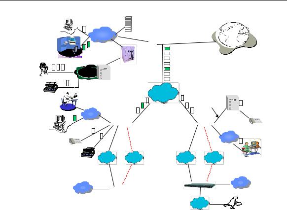
1.5 Typical Application
1-3
Installation Manual |
|
Chapter 1 |
Quidway R2600/3600 Series Modular Routers |
|
Introduction |
Quidway routers enterprise network solution |
||
Server |
GK |
|
|
|
|
LAN |
Central network |
|
|
LAN |
Quidway3680 |
E1 trunk |
A8010 Refiner |
|
|
||
|
Internet
Phone |
PBX |
PBX
FAX |
|
|
DDN/FR |
|
|
Branch Intranet |
|
|
AT0/E&M |
|
|
LAN |
QuidwayR2600 3600 |
QuidwayR2600/3600 |
|
||
|
|
/ |
|
||
|
LAN |
|
|
LAN |
Branch Intranet |
|
|
|
|
||
|
DDN/FR/ |
PSTN/ |
DDN/FR/ |
PSTN/ |
|
|
X25 |
ISDN |
X25 |
ISDN |
|
Level-3 Intranet |
|
|
Level-3 Intranet |
||
|
Quidway2511/2509/4001 |
LAN |
|||
LAN |
|
|
|||
|
|
|
|
|
|
|
Quidway |
1602/1603/1604 |
|
ISDN/ |
|
|
|
|
|
PSTN |
|
representative office
The red dotted line stands for backup line.
Figure 1-1 Typical application of Quidway R2600/3600 series routers
1-4

Installation Manual |
Chapter 2 |
Quidway R2600/3600 Series Modular Routers |
Appearance and System Features |
Chapter 2 Appearance and System Features
2.1 Quidway R2620/R2621
2.1.1Appearance
I.Appearance of R2620
The front panel and rear panel of R2620 are shown in the following figures.
SLOT0 SLOT1 WAN0 WAN1 |
LAN0 |
|
POWER |
READY |
LINK |
SYSTEM |
ACTIVEACTIVE |
|
Figure 2-1 Front panel of R2620
WAN1 |
|
WAN0 |
AUX |
CO NSO LE |
|
|
|
Figure 2-2 Rear panel of R2620
II. Appearance of R2621
The front panel and rear panel of R2621 are shown in the following figures.
SLOT0 SLOT1 WAN0 WAN1 |
LAN0 LAN1PO |
|
POWER |
READY |
LINK |
SYSTEM |
ACTIVE ACTIVE |
|
Figure 2-3 Front panel of R2621
WAN1 |
WAN0 |
AUX CONSOLE
Figure 2-4 Rear panel of R2621
2-1
Installation Manual |
Chapter 2 |
Quidway R2600/3600 Series Modular Routers |
Appearance and System Features |
2.1.2 Indicators on Panel
The meanings of indicators on the front panel of R2620/R2621 are shown in the following table.
Table 2-1 Meanings of indicators on the front panel of R2620/R2621
Indicator |
Meaning |
|
|
|
|
POWER |
System power indicator: Off means power is off. On means power is on. |
|
SYSTEM |
Hardware status indicator. Blinking means system is normal. Always on/off |
|
means system is abnormal. |
||
|
||
READY |
Module indicator. On means the module of the current slot is working normally. |
|
Off means the module is abnormal or no module is installed in the current slot. |
||
|
||
|
Blinking means data is being received and transmitted by the module in the |
|
ACTIVE |
current slot. Off means no data is being received or transmitted by the module in |
|
|
the corresponding slot. |
|
LINK |
Off means the LAN line is not connected. On means the LAN line is connected. |
|
SLOT0-SLOT1 |
Indicating the corresponding slot number. |
|
WAN0-WAN1 |
Indicating the corresponding WAN interface number. |
|
LAN0, LAN1 (only for R2621) |
Indicating the corresponding Ethernet interface number. |
The attributes of WAN0 and WAN1 interfaces of R2620/2621 are described in the following table.
Table 2-2 Attributes of WAN0 and WAN1 interfaces of R2620/2621
Attribute |
|
Synchronous |
|
|
|
|
|
Connector |
DB-50 |
|
|
Interface standards and |
V.24 |
|
V.35 |
DTE |
|
DTE |
|
operating mode |
|
||
DCE |
|
DCE |
|
|
|
||
Minimum baud rate (bit/s) |
1200 |
|
1200 |
Maximum baud rate (bit/s) |
64K |
|
2.048M |
|
---Modem dial-up |
|
|
Services supported |
---Backup |
|
|
|
---Terminal access service |
|
|
|
---PPP |
|
|
|
---MP |
|
|
Protocols supported |
---LAPB |
|
|
---X.25 |
|
|
|
|
---HDLC |
|
|
|
---SDLC |
|
|
|
---Frame Relay |
|
|
2.1.3 System Description
The table below shows the basic configurations, dimensions, operating environment, etc. of R2620 and R2621.
2-2
Installation Manual |
|
|
Chapter 2 |
|||
Quidway R2600/3600 Series Modular Routers |
|
Appearance and System Features |
||||
|
Table 2-3 System description of R2620/R2621 |
|
|
|
||
|
|
|
|
|
|
|
|
Item |
|
Description of R2620 |
|
Description of R2621 |
|
|
|
|
|
|
||
|
Slot |
|
A maximum of 2 function modules can be |
configured according to |
||
|
|
requirement. |
|
|
|
|
|
|
|
|
|
|
|
|
CPU |
|
Power PC 8240 200MHz |
|
|
|
|
BOOT ROM |
|
512KB |
|
512KB |
|
|
SDRAM |
|
Default: 32MB |
|
|
|
|
|
Max.: 128MB |
|
|
|
|
|
|
|
|
|
|
|
|
FLASH |
|
8MB |
|
|
|
|
Dimensions |
|
Width x Height x Depth = 440mm x 86mm x 300mm |
|||
|
Weight |
|
5kg |
|
|
|
|
Input voltage |
|
AC: 85V to 264V 50/60Hz |
|
|
|
|
|
DC: -40V to -75V |
|
|
|
|
|
|
|
|
|
|
|
|
Max. Power |
|
70W |
|
|
|
|
Operating temperature |
|
0 to 40OC |
|
|
|
|
Operating humidity |
|
10 to 90% non-condensing |
|
|
|
Note:
Dynamic memory (DRAM/SDRAM) works as main memory.
FLASH stores system programs.
2.2 Quidway R2630/R2630E
2.2.1 Appearance
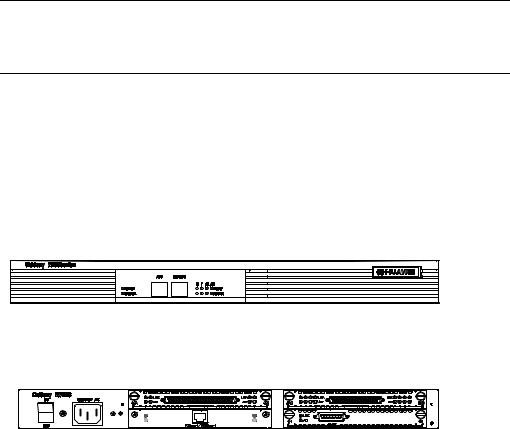
For R2630 and R2630E, their front panels and rear panels are very similar, see their outlook as the following (take R2630 as an example).
Figure 2-5 Front panel of R2630
Figure 2-6 Rear panel of R2630
2.2.2 Indicators on Panel
The meanings of indicators on the front and rear panels of R2630/R2630E are shown in the following tables.
2-3

Installation Manual |
|
|
Chapter 2 |
||
Quidway R2600/3600 Series Modular Routers |
Appearance and System Features |
|
|||
|
Table 2-4 |
Meanings of indicators on the front panel of R2630/R2630E |
|||
|
|
|
|
||
|
Indicator |
|
Meaning |
||
|
|
|
|
||
|
POWER |
|
System power indicator: Off means power is off, On means power is on. |
||
|
SYSTEM |
|
Hardware status indicator. Blinking means the system runs normally. Always on/off |
||
|
|
means the system is abnormal. |
|||
|
|
|
|||
|
READY |
|
Module status indicator: On means the module in corresponding slot runs normally. |
||
|
|
Off means the module runs abnormally or no module is installed. |
|||
|
|
|
|||
|
ACTIVE |
|
Blinking means data |
is being received or transmitted by the module in the |
|
|
|
corresponding slot. Off means no data is being received or transmitted |
|||
|
|
|
|||
|
0 - 2 |
|
Indicating the slot number. |
||
|
LAN |
|
Ethernet interface indicator: Green means the interface is normal. Blinking yellow |
||
|
|
means data is being received and transmitted over the Ethernet. |
|||
|
|
|
|||
|
Table 2-5 |
Meanings of indicators on the rear panel of R2630/R2630E |
|||
|
|
|
|
||
|
Indicator |
|
Meaning |
||
|
|
|
|
||
|
LINK |
|
Off means the Ethernet link is not connected. On means the link is connected. |
||
|
ACTIVE |
|
Off means no data is |
being received and transmitted by the Ethernet interface. |
|
|
|
Blinking means data is being received or transmitted. |
|||
|
|
|
|||
2.2.3 System Description
The following table shows the basic configuration, dimensions, operating environment, etc. of R2630 and R2630E.
Table 2-6 System description of R2630/R2630E
Item |
Description of R2630 |
Description of R2630E |
|
|
|
|
|
Slot |
A maximum of 3 interface modules can |
be configured according to |
|
requirement. |
|
||
|
|
||
CPU |
Pentium 133MHz |
Power PC 8240 200MHz |
|
NVRAM |
128KB |
128KB |
|
BOOTROM |
512KB |
512KB |
|
SDRAM |
None |
Default: 64MB |
|
Max.: 256MB |
|||
|
|
||
DRAM |
Default: 32MB |
None |
|
Max.: 128MB |
|||
|
|
||
FLASH |
8MB |
|
|
Dimensions |
Width x Height x Depth = 440mm x 43mm x 400mm |
||
Weight |
8kg |
|
|
Input voltage |
AC: 160 to 240V 50/ 60Hz |
AC: 85 to 264V 50/60Hz |
|
DC: -40 to -75V |
|
||
|
|
||
Max. power |
80W |
|
|
Operating temperature |
0 to 40OC |
|
|
Operating humidity |
10 to 90% non-condensing |
|
|
Note:
Dynamic memory (DRAM/SDRAM) works as main memory.
FLASH stores system programs.
NVRAM stores configuration files.
2-4
Installation Manual |
Chapter 2 |
Quidway R2600/3600 Series Modular Routers |
Appearance and System Features |
2.3 Quidway R2631/R2631E |
|
2.3.1 Appearance
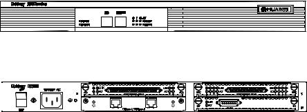
For R2631 and R2631E, their front panels and rear panels are very similar, see their outlook as the following (take R2631 as an example).
Figure 2-7 Front panel of R2631
Figure 2-8 Rear panel of R2631
2.3.2 Indicators on Panels
The meanings of indicators on the front and rear panels of R2631 and R2631E are shown in the following tables.
Table 2-7 Meanings of indicators on the front panel of R2631/R2631E
Indicator |
Meaning |
|
|
|
|
POWER |
System power indicator: Off means power is off. On means power is on. |
|
SYSTEM |
Hardware status indicator: Blinking means system is normal. Always on/off means the |
|
system is abnormal. |
||
|
||
READY |
Module status indicator: On means the module runs normally in the current slot. Off |
|
means the module runs abnormally or no module is installed. |
||
|
||
ACTIVE |
Blinking means data is being received or transmitted by the module in the current slot. Off |
|
means no data is being received or transmitted by the module in the current slot. |
||
|
||
0 - 2 |
Position of the corresponding slots. |
|
LAN |
Ethernet interface indicator. Green means the interface is normal. Blinking yellow means |
|
that data is being received or transmitted over the Ethernet. |
||
|
Table 2-8 Meanings of indicators on the rear panel of R2631/R2631E
Indicator |
Meaning |
|
|
|
|
LINK |
Off means the Ethernet link is not connected. On means the link is connected. |
|
ACTIVE |
Off means no data is being received or transmitted by the Ethernet interface. Blinking |
|
means data is being received or transmitted. |
||
|
||
0 - 1 |
Corresponding port number. |
2-5
Installation Manual |
Chapter 2 |
Quidway R2600/3600 Series Modular Routers |
Appearance and System Features |
2.3.3 System Description
The following table shows the basic configuration, dimensions, operating environment, etc. of R2631 and R2631E.
Table 2-9 System description of R2631/R2631E
Item |
Description of R2631 |
Description of R2631E |
|
|
|
|
|
Slot |
A maximum of 3 interface modules can be configured according to |
||
requirement. |
|
||
|
|
||
CPU |
Pentium133MHz |
Power PC 8240 200MHz |
|
NVRAM |
128KB |
|
|
BOOT ROM |
512KB |
|
|
SDRAM |
None |
Default: 64MB |
|
Max.: 256MB |
|||
|
|
||
DRAM |
Default: 32MB |
None |
|
Max.: 128MB |
|||
|
|
||
FLASH |
8MB |
|
|
Dimensions |
Width x Height x Depth = 440mm x 43mm x 400mm |
||
Weight |
8kg |
|
|
Input voltage |
AC: 160 to 240V 50/ 60Hz |
AC: 85 to 264V 50/ 60Hz |
|
DC: -40V to -75V |
|
||
|
|
||
Max. power (with 3 modules) |
80W |
|
|
Operating temperature |
0 to 40OC |
|
|
Operating humidity |
10 to 90% non-condensing |
|
|
Note:
Dynamic memory (DRAM/SDRAM) works as main memory.
FLASH stores system programs.
NVRAM stores configuration files.
2.4 Quidway R3640/R3640E
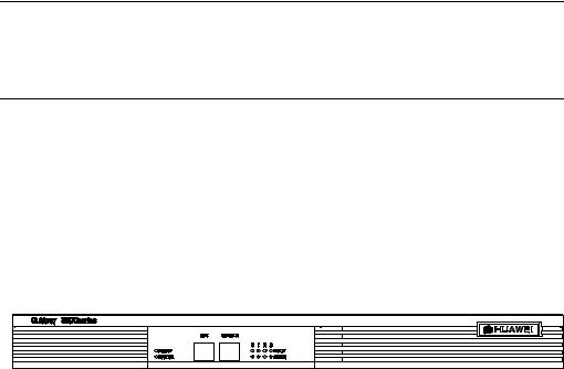
2.4.1 Appearance
For R3640 and R3640E, their front panels and rear panels are very similar, see their outlook as the following (take R3640 as an example)
Figure 2-9 Front panel of R3640
2-6
Installation Manual |
Chapter 2 |
Quidway R2600/3600 Series Modular Routers |
Appearance and System Features |
Figure 2-10 Rear panel of R3640
2.4.2 Indicators on Panel
The meanings of indicators on the front panel of R3640/R3640E are shown in the following table.
Table 2-10 Meanings of indicators on the front panel of R3640/R3640E
Indicator |
Meaning |
|
|
|
|
POWER |
System power indicator: Off means power is off. On means power is on. |
|
SYSTEM |
Hardware status indicator: Blinking means system is normal. Always on/off means |
|
system is abnormal. |
||
|
||
READY |
Module indicator. On means the module of the current slot is working normally. Off |
|
means the module is abnormal or no module is installed in the current slot. |
||
|
||
|
Blinking means data is being received and transmitted by the module in the current |
|
ACTIVE |
slot. Off means no data is being received or transmitted by the module in the current |
|
|
slot. |
|
0 - 3 |
Position of corresponding slots. |
2.4.3 System Description
The following table shows the basic configurations, dimensions, operating environment, etc. of R3640 and R3640E.
2-7
Installation Manual |
|
Chapter 2 |
||
Quidway R2600/3600 Series Modular Routers |
Appearance and System Features |
|||
Table 2-11 System Description of R3640/R3640E |
|
|
||
|
|
|
|
|
|
Item |
Description of R3640 |
Description of R3640E |
|
|
|
|
|
|
|
Slot |
A maximum of 4 function modules can be configured according to requirement. |
||
|
Processor |
Pentium 133MHz |
Power PC 8240 250MHz |
|
|
NVRAM |
128KB |
|
|
|
BOOT ROM |
512KB |
|
|
|
SDRAM |
None |
Default: 128MB |
|
|
Max.: 256MB |
|||
|
|
|
||
|
DRAM |
Default: 32MB |
None |
|
|
Max.: 128MB |
|||
|
|
|
|
|
|
FLASH |
8MB |
|
|
|
Dimensions |
Width x Height x Depth = 440mm x 43mm x 400mm |
||
|
Weight |
8kg |
|
|
|
Input voltage |
AC: 160 to 240V 50/60Hz |
AC: 85 to 264V 50/60Hz |
|
|
DC: -40V to -75V |
|
|
|
|
|
|
|
|
|
Max. power (with 4 modules) |
80W |
|
|
|
Operating temperature |
0 to 40OC |
|
|
|
Operating humidity |
10 to 90% non-condensing |
|
|
Note:
Dynamic memory (DRAM/SDRAM) works as main memory.
FLASH stores system programs.
NVRAM stores configuration files.
2.5 Quidway R3680/R3680E
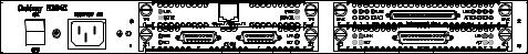
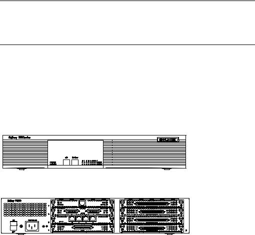
2.5.1 Appearance
For R3680 and R3680E, their front panels and rear panels are very similar, see their outlook as the following (take R3680 as an example)
Figure 2-11 Front panel of R3680
Figure 2-12 Rear panel of R3680/R3680E
2-8
Installation Manual |
Chapter 2 |
Quidway R2600/3600 Series Modular Routers |
Appearance and System Features |
2.5.2 Indicators on Panel
The meanings of indicators on the front panel of R3680/R3680E are shown in the following table.
Table 2-12 Meanings of indicators on the front panel of R3680/R3680E
Indicator |
Meaning |
|
|
|
|
POWER |
System power indicator: Off means power is off. On means power is on. |
|
SYSTEM |
Hardware status indicator: Blinking means system is normal. Always on/off means |
|
system is abnormal. |
||
|
||
READY |
Module indicator. On means the module of the current slot is working normally. Off |
|
means the module is abnormal or means no module is installed in the current slot. |
||
|
||
ACTIVE |
Blinking means data is being received and transmitted by the module on the current slot. |
|
Off means no data is being received or transmitted by the module in the current slot. |
||
|
||
0 - 7 |
Position of corresponding slots. |
2.5.3 System Description
The following table shows the basic configurations, dimensions, operating environment, etc. of R3680 and R3680E.
Table 2-13 System description of R3680/R3680E
Item |
Description of R3680 |
|
Description of R3680E |
|
|
|
|
|
|
Slot |
A maximum of 8 function modules can be configured according to |
|||
requirement. |
|
|
||
|
|
|
||
CPU |
Pentium MMX-166MHz |
Power PC 8240 250MHz |
||
NVRAM |
128KB |
|
|
|
BOOT ROM |
512KB |
|
|
|
SDRAM |
None |
Default: 128MB |
||
Max.: 256MB |
||||
|
|
|||
DRAM |
Default: 64MB |
None |
||
Max.: 128MB |
||||
|
|
|
||
FLASH |
8MB |
|
|
|
Dimensions |
Width x Height x Depth = 440mm x 86mm x 400mm |
|||
Weight |
14kg |
|
|
|
Input voltage |
AC: 160 to 240V 50/ 60Hz |
AC: 85 to 264V 50/60Hz |
||
DC: -40V to -75V |
|
|
||
|
|
|
||
Max. power (with 8 modules) |
130W |
|
120W |
|
Operating temperature |
0 to 40OC |
|
|
|
Operating humidity |
10 to 90% non-condensing |
|
|
|
Note:
Dynamic memory (DRAM/SDRAM) works as main memory.
FLASH stores system programs.
NVRAM stores configuration files.
2-9
Installation Manual |
Chapter 3 |
Quidway R2600/3600 Series Modular Routers |
Installation Preparations |
Chapter 3 Installation Preparations
3.1 Safety Recommendations
Routers play the key role in data communications network. Please pay attention to the following:
 Warning: It indicates that this operation may seriously damage the router or endanger the operator. Please follow the operation procedures for sake of safety.
 Caution: It indicates that during the installation and usage of the router, the operation needs attention. Though this operation will not do any damage to the router or endanger the operator, it may affect the normal operation of the router.
Please follow the following safety recommendations during the installation and use of the router:
zKeep the router away from water or any wet place.
zKeep the router away from any heat source.
zMake sure that the router is normally grounded.
zWear ESD-preventive wrist strap during installation.
zDo not hot unplug the modules of the router.
zDo not hot unplug any cable.
zAlways use UPS.
3.2Installation Conditions
R2600/3600 series must be used indoors. To ensure the normal operation and prolong their service life, the following requirements for installation site must be met.
3.2.1 Temperature and Humidity Requirements
Certain requirements on temperature and humidity in the equipment room shall be met. If the relative humidity is too high, the insulation materials in it will deteriorate easily or even lead to electric leakage. Sometimes this will result in change to the mechanical performance of the materials and rusting of the metal components. If the relative humidity is too low, the fastening screw will become loosen due to shrinkage of the isolation spacer. In an environment with dry climate, the static electricity may be produced, putting the CMOS of the router to risk. High temperature is of the greatest risk: for it will significantly degrade the router’s reliability, speed up the aging process of the insulating materials, and shorten the service life of the router. The requirements on the temperature and humidity for R2600/3600 series are shown in Table 3-1:
3-1

Installation Manual |
|
|
|
|
|
Chapter 3 |
||
Quidway R2600/3600 Series Modular Routers |
|
Installation Preparations |
||||||
Table 3-1 Humidity requirement in the equipment room |
|
|
|
|
||||
|
|
|
|
|
|
|
|
|
|
|
Temperature |
|
|
Relative humidity |
|||
|
|
|
|
|
|
|
|
|
|
Normal operating condition |
Safety operating |
|
Normal operating condition |
Safety operating |
|||
|
condition |
|
condition |
|||||
|
|
|
|
|
|
|||
|
|
|
|
|
|
|
|
|
|
15OC to 30OC |
|
0OCto 45OC |
|
40% to 65% |
|
10% to 90% |
|
Note:
1)The values of environmental temperature and humidity in the equipment room are measured at 1.5m high and 0.4m away from the front of the router rack when there is no protective board installed in front and at the back of the rack.
2)Safety operating condition refers to the continuous operation for less than 48 hours or the accumulative annual operation time less than 15 days.
3)The extreme environment refers to the likely environmental temperature and humidity when the air conditioning system in the equipment room fails (the normal operating condition should be recovered
within five hours for each failure).
3.2.2 Cleanness Requirements
Dust undermines the normal operation of R2600/3600 series. Dust dropping on the equipment can cause electrostatic adsorption, which degrades the contact performance of the metal connection parts or connectors. This happens more frequently when the indoor relative humidity is low, which will not only shorten the router’s service life, but also cause communication failure.
The recommended specification on dust content and particle diameter in the equipment room is shown in Table 3-2:
Table 3-2 Specification on dust content in equipment room
Maxim diameter ( m) |
Max. intensity (particles per cubic meter) |
|
|
0.5 |
1.4 x 10⁷ |
1 |
7 x 10⁵ |
3 |
2.4 x 10⁵ |
5 |
1.3 x 10⁵ |
The routers also have rigorous demand on the content of salts, acids and sulfides in the air. These harmful gases will speed up the metal rusting and the aging processes of certain parts. The equipment room should be protected from the invasion of harmful gases such as SO2, H2S, NO2, NH3 and Cl2, the value limits of which are shown in Table 3-3:
3-2
Installation Manual |
|
Chapter 3 |
||
Quidway R2600/3600 Series Modular Routers |
|
Installation Preparations |
||
Table 3-3 Value limits for harmful gas contents in equipment room |
|
|
||
|
|
|
|
|
|
Gas |
Average (mg/m3) |
Max. (mg/m3) |
|
|
SO2 |
0.2 |
1.5 |
|
|
H2S |
0 |
0.03 |
|
|
NO2 |
0.04 |
0.15 |
|
|
NH3 |
0.05 |
0.15 |
|
|
Cl2 |
0.01 |
0.3 |
|
3.2.3 ESD-Preventive Requirements
Although many antistatic considerations have been given to R2600/3600 series, damage to the router’s circuit or even the whole equipment may still happen when the static electricity exceeds the tolerance threshold.
In the communication network to which the routers are connected, static induction mainly comes from:
zExternal electric fields such as outdoor high voltage power line or thunder.
zInternal environment like flooring materials or the whole equipment structure.
Thus, the following should be considered to safeguard the equipment against the static damage:
zMake sure that the equipment and the floor are well grounded.
zMake sure that dust-proof measures are taken.
zMaintain an appropriate humidity and temperature.
zWear an ESD-preventive wrist strap and uniform when contacting the circuit board.
zPlace the uninstalled circuit board on the antistatic workbench, with its face upward, or put it into the electromagnetic shield bag.
zWhen observing or removing the uninstalled circuit board, please touch the edge of the circuit board, and avoid contacting the devices on it.
3.2.4Anti-interference Requirements
The interference sources, no matter where they come from, affect the routers with capacitance coupling, inductance coupling, radiation of electromagnetic wave, common impedance (including the grounding system) or conducting line (power line, signal line and transmission line etc.).
So the following should be considered:
zTake effective measures to prevent the power system from being interfered with by the power grid system.
zSeparate the working ground of the router from the grounding device of the power supply equipment or anti-lightning grounding device as far as possible.
zKeep the router far away from the radio launcher, radar launcher, and highfrequency devices working in high currents.
zUse electromagnetic shielding when necessary.
3.2.5Lightning Protection Requirements
Although many measures have been taken to protect R2600/3600 series from lightning, if the lightning intensity exceeds a certain range, damage to the router may still happen. To protect the router from lightning better, the following should be considered:
3-3

Installation Manual |
Chapter 3 |
Quidway R2600/3600 Series Modular Routers |
Installation Preparations |
zEnsure the shell of the chassis is well grounded through the ground wire.
zEnsure the neutral point of the socket of AC power supply is well grounded.
zTo enhance the lightning protection capability of the power supply, a lightning arrester could be installed at the input end of the power supply.
zAs for the signal line led out to the outdoor from the function modules of R2600/3600 series, such as ISDN line, telephone line, E1 line, etc, a special lightning arrester should be installed at the input end of the signal line to enhance the lightning protection capability.
3.2.6Workbench Requirements
No matter whether you are to install the router in the cabinet or directly place it on the workbench, it is necessary to ensure that:
zThere is spacing reserved at the air inlet and outlet in the router so as to facilitate the radiation of the router cabinet.
zThe cabinet and workbench have good radiation systems.
zThe cabinet and workbench are firm enough to support the weight of the router and other installation accessories.
zThe cabinet and workbench are well grounded.
3.3Tools and Devices Required
1)Tools required
zPhillips screwdriver
zFlathead screwdriver
zESD-preventive wrist strap
2)Connection cables z Power cable
z Console cable z Auxiliary cable z Ethernet cable
z Interface cable for selected modules
3)Required Devices
zEthernet HUB or LANSWITCH
zCSU/DSU or other DCE
zConfiguration terminal (can be an ordinary PC)
zEquipment related with selected modules
 Caution:
R2600/3600 series are not equipped with any installation tools, and the user has to prepare the tools.
3-4
Installation Manual |
Chapter 4 |
Quidway R2600/3600 Series Modular Routers |
Installation |
Chapter 4 Installation
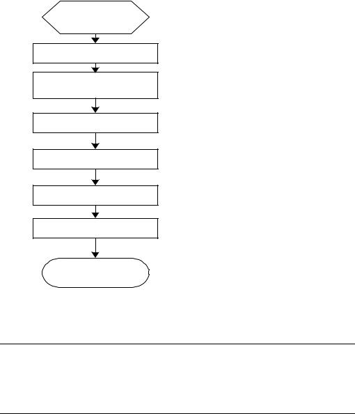
4.1 Installation Flow
Begin to install
Preparation and confirmation
Connect the router to the specified position
Connect various cables
Check after installation
Power on
Configure the router
Installation completed
Figure 4-1 Flow for installing R2600/3600 series routers
 Caution:
Before starting the work described in 4.2 and 4.3, please make sure:
1)You have carefully read Chapter 3 Installation Preparations.
2)The requirements specified in Chapter 3 have been met.
4.2Mechanical Installation
When you have completed the above work, you can start to install the router.
There are two methods for installing the router depending on the installation position:
4-1
Installation Manual |
Chapter 4 |
Quidway R2600/3600 Series Modular Routers |
Installation |
zInstalling it in the cabinet
zPlacing it on the workbench
4.2.1Installing the Router in a Cabinet
R2600/3600 series have been designed according to the size of the standard 19-inch cabinet, and their dimensions are respectively:
Quidway R3680, R3680E: Width x height x depth = 440mm x 86mm x 400mm
Quidway R2630, R2630E, R2631, R2631E, R3640, and R3640E:
Width x height x depth = 440mm x 43mm x 400mm
Quidway R2620, R2621: Width x height x depth = 440mm x 86mm x 300mm
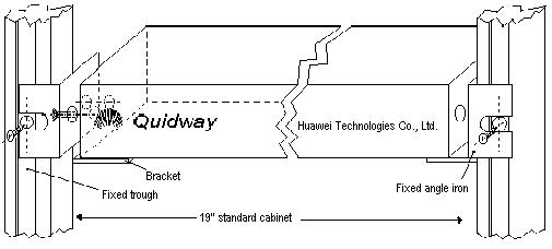
As shown in Figure 4-2, the flow for installing the router is as follows:
Step 1: Check the grounding condition and secureness of the cabinet. Secure the bracket to both sides of the front/rear panel of the router.
Step 2: Place the router on one of the trays in the cabinet. Move the router to a proper position along the guide rail in the cabinet. Leave an appropriate space between the router and guide rail.
Step 3: Screw the bracket to the fixed guide rail at both sides of the cabinet.
In this way, the router is firmly fixed to the cabinet through the tray at each slot in the cabinet and the bracket of the router.
Figure 4-2 Mechanical installation of the Quidway R26/ 36 series
4.2.2 Installing the Router on Workbench
In most of the cases, you do not have a standard 19-inch cabinet. Then, you can place the routers on clean workbenches. This is a simple operation. During this operation, the operator:
zMust ensure the stability and good grounding of the workbench.
zMust reserve a 10cm for heat-dissipation around the router.
zDo not place any heavy object on the router.
4-2
Installation Manual |
Chapter 4 |
Quidway R2600/3600 Series Modular Routers |
Installation |
4.3 Power Connection |
|
4.3.1 Connecting Power Cable
R2600/3600 series support the AC/DC power modules (See Chapter 2 Appearance and System Features). You can select different types of power modules according to the specific environment where the router is used.
The AC and DC routers of R2600/3600 series have basically the same features and functions. They differ in their input voltages only.
I.AC power and power cable
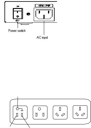
z AC power
For the power socket of the AC-input router, see Figure 4-3. Input power:
180 to 240V, 50/60Hz AC (R2630, R2631, R3640, and R3680)
85 to 264V, 50/60Hz AC (R2630E, R2631E, R3640E, R3680E, R2620 and R2621)
Figure 4-3 Power socket of AC-input router
zRecommended AC power socket
A monophase 3-wire power socket with a neutral point connector, or a special power socket for the computer is recommended. The neutral point of the power in a building must be reliably grounded. Normally, the neutral point of the power supply system in a building will have been grounded during the construction and wiring. The user must make sure that the power supply for the building is earthed.
Neutral point
Zero line |
Live line |
|
Figure 4-4 Recommended AC power socket
zConnecting AC cable
4-3
Installation Manual |
Chapter 4 |
Quidway R2600/3600 Series Modular Routers |
Installation |
Step 1: Connect one end of the ground cable on the chassis accompanying the router to the ground pin on the router’s rear panel, and well ground the other end.
Step 2: After confirming the power switch of the router is turned off, connect one end of the power line accompanying the router to the power input socket on the router’s rear panel, and connect the other end to the AC socket that delivered with the router.
Step 3: Switch the power switch of the router to the ON position.
Step 4: Check that the power indicator on the rear panel of the router is on. On means the power cable is correctly connected.
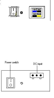
II. DC power and DC cable
zDC power
Input power: -45V to -70V DC
R3640, R3640E, R3680, R3680E, R2630E, and R2631E routers use the DC-input socket, as shown in Figure 4-5.
|
|
|
|
|
|
|
|
|
|
|
|
|
|
|
|
|
|
|
|
|
|
|
|
|
|
|
|
|
|
|
|
|
|
|
|
|
|
|
|
|
|
|
|
|
|
|
|
|
|
|
|
|
|
|
|
|
|
|
|
|
|
|
|
|
|
|
Power switch |
|
DC-input |
|
||||||
Figure 4-5 Power socket of DC-input router (R3640/R3680/R2630E/R2631E/R3640E/R3680E)
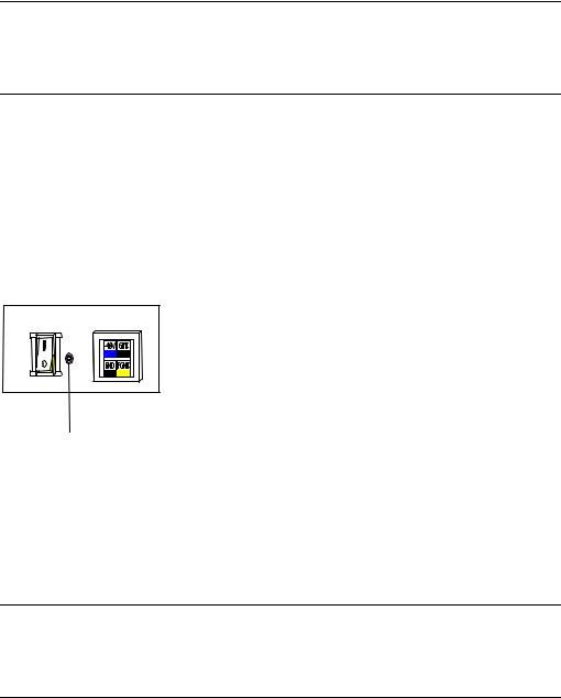
R2620 and R2621 routers use the DC-input socket, as shown in Figure 4-6.
Figure 4-6 Power socket of DC-input router (R2620/R2621)
zConnecting DC cable
Step 1: Connect one end of the ground cable on the chassis accompanying the router to the ground pin on the router’s rear panel, and well ground the other end.
Step 2: After confirming the power switch of the router is turned off, connect one end of the power line accompanying the router to the power socket on the router’s rear panel, and connect the other end to the –48V DC power of the switch.
Step 3: Switch the power switch of the router to the ON position.
4-4
Installation Manual |
Chapter 4 |
Quidway R2600/3600 Series Modular Routers |
Installation |
Step 4: Check that the power indicator in the rear panel of the router is on. It is on when the power cable is correctly connected.
4.3.2 Connecting Ground Cable
 Warning:
The normal connection of the router’s ground cable is the primary guarantee for the anti-lightning and anti-interference capability of the router, so you must connect the ground cable carefully.
The AC input connector of R2600/3600 series comes with an AC noise filter unit, whose central ground is directly connected with the cabinet, forming the so-called chassis ground (also called the protection ground). This chassis must be well grounded so that the induction power and leakage power can be released to the ground to improve the whole router’s performance to withstand electromagnetic interference. This ground also provides protection against the lightning and over-voltage likely to be caused by the external network cable such as the E1 interface and ISDN cables.
The ground point of the chassis is located near the AC power and switch at the back of the cabinet, as shown in Figure 4-7. The point shall be connected to the ground.
Ground point
Figure 4-7 Ground point on the chassis
Please connect this point to the ground with a ground cable, and make sure that the ground resistance is not greater than 5-ohm. If the router is installed in a standard 19inch cabinet, then this cabinet should be grounded in the same way.
 Warning:
The router must be well grounded for the normal working; otherwise it cannot guard against lightning, and is likely to cause damage to the router and the far-end equipment connected with this router!
4.4 Connecting Interface Cable on Main Control Panel
Note that Console and AUX interface cannot be used at the same time. You can only choose either of them.
4-5
Loading...