


 Loading...
RRU3249
Installation Guide
Issue DraftA
Date 2015-05-30
HUAWEI TECHNOLOGIES CO., LTD.

Copyright © Huawei Technologies Co., Ltd. 2015. All rights reserved.
No part of this document may be reproduced or transmitted in any form or by any means without prior written consent of Huawei Technologies Co., Ltd.
Trademarks and Permissions


 and other Huawei trademarks are trademarks of Huawei Technologies Co., Ltd.
All other trademarks and trade names mentioned in this document are the property of their respective holders.
Notice
The purchased products, services and features are stipulated by the contract made between Huawei and the customer. All or part of the products, services and features described in this document may not be within the purchase scope or the usage scope. Unless otherwise specified in the contract, all statements, information, and recommendations in this document are provided "AS IS" without warranties, guarantees or representations of any kind, either express or implied.
The information in this document is subject to change without notice. Every effort has been made in the preparation of this document to ensure accuracy of the contents, but all statements, information, and recommendations in this document do not constitute a warranty of any kind, express or implied.
Huawei Technologies Co., Ltd.
Address: |
Huawei Industrial Base |
|
Bantian, Longgang |
|
Shenzhen 518129 |
|
People's Republic of China |
Website: |
http://www.huawei.com |
Email: |
support@huawei.com |
Issue DraftA (2015-05-30) |
Huawei Proprietary and Confidential |
i |
|
Copyright © Huawei Technologies Co., Ltd. |
|

RRU3249 |
|
Installation Guide |
About This Document |
About This Document
Purpose
This document describes the process of installing a DC blade RRU3249 (referred to as RRU in this document).
Product Version
The following table lists the product version related to this document.
Product Name |
Solution Version |
Product Version |
|
|
|
DBS3900 |
• SRAN8.0 and later |
V100R008C00 and later |
|
versions |
versions |
|
• eRAN6.0 and later |
|
|
versions |
|
|
|
|
Intended Audience
This document is intended for:
Base station installation engineers
Organization
1 Changes in the RRU3249 Installation Guide
This chapter describes the changes in the RRU3249 Installation Guide.
2 Installation Preparations
This chapter describes the reference documents, tools, and instruments that must be ready before the installation. In addition, it specifies the skills and prerequisites that installation engineers must have.
3 Information About the Installation
Before installing an RRU, you must be familiar with its exterior, ports, indicators, installation options and installation clearance requirements.
Issue DraftA (2015-05-30) |
Huawei Proprietary and Confidential |
ii |
|
Copyright © Huawei Technologies Co., Ltd. |
|

RRU3249 |
|
Installation Guide |
About This Document |
4 Unpacking the Equipment
This chapter describes how to unpack and check the delivered equipment to ensure that all the materials are included and intact.
5 Installation Process
The installation process involves installing an RRU and RRU cables, checking the RRU hardware installation, and powering on the RRU.
6 Installing the RRU
This chapter describes the procedure for installing the RRU. The procedure for installing the RRU varies depending on installation options.
7 Installing RRU Cables
This chapter describes the procedure for installing RRU cables.
8 Checking the RRU Hardware Installation
After an RRU is installed, check the hardware installation.
9 Powering On an RRU
After all the devices are installed, check the power-on status of an RRU.
10 Appendix
Conventions
Symbol Conventions
The symbols that may be found in this document are defined as follows.
Symbol |
Description |
|
|
|
Indicates an imminently hazardous situation which, if not |
|
avoided, will result in death or serious injury. |
|
|
|
Indicates a potentially hazardous situation which, if not |
|
avoided, could result in death or serious injury. |
|
|
|
Indicates a potentially hazardous situation which, if not |
|
avoided, may result in minor or moderate injury. |
|
|
|
Indicates a potentially hazardous situation which, if not |
|
avoided, could result in equipment damage, data loss, |
|
performance deterioration, or unanticipated results. |
|
NOTICE is used to address practices not related to personal |
|
injury. |
|
|
Issue DraftA (2015-05-30) |
Huawei Proprietary and Confidential |
iii |
|
Copyright © Huawei Technologies Co., Ltd. |
|

RRU3249 |
|
|
Installation Guide |
About This Document |
|
|
|
|
|
Symbol |
Description |
|
|
|
|
|
Calls attention to important information, best practices and |
|
|
tips. |
|
|
NOTE is used to address information not related to personal |
|
|
injury, equipment damage, and environment deterioration. |
|
|
|
General Conventions
The general conventions that may be found in this document are defined as follows.
Convention |
Description |
|
|
Times New Roman |
Normal paragraphs are in Times New Roman. |
|
|
Boldface |
Names of files, directories, folders, and users are in |
|
boldface. For example, log in as user root. |
|
|
Italic |
Book titles are in italics. |
|
|
Courier New |
Examples of information displayed on the screen are in |
|
Courier New. |
|
|
Command Conventions
The command conventions that may be found in this document are defined as follows.
Convention |
Description |
|
|
Boldface |
The keywords of a command line are in boldface. |
|
|
Italic |
Command arguments are in italics. |
|
|
[ ] |
Items (keywords or arguments) in brackets [ ] are optional. |
|
|
{ x | y | ... } |
Optional items are grouped in braces and separated by |
|
vertical bars. One item is selected. |
|
|
[ x | y | ... ] |
Optional items are grouped in brackets and separated by |
|
vertical bars. One item is selected or no item is selected. |
|
|
{ x | y | ... }* |
Optional items are grouped in braces and separated by |
|
vertical bars. A minimum of one item or a maximum of all |
|
items can be selected. |
|
|
[ x | y | ... ]* |
Optional items are grouped in brackets and separated by |
|
vertical bars. Several items or no item can be selected. |
|
|
GUI Conventions |
|
Issue DraftA (2015-05-30) |
Huawei Proprietary and Confidential |
iv |
|
Copyright © Huawei Technologies Co., Ltd. |
|

RRU3249 |
|
Installation Guide |
About This Document |
The GUI conventions that may be found in this document are defined as follows.
Convention |
Description |
|
|
Boldface |
Buttons, menus, parameters, tabs, window, and dialog titles |
|
are in boldface. For example, click OK. |
|
|
> |
Multi-level menus are in boldface and separated by the ">" |
|
signs. For example, choose File > Create > Folder. |
|
|
Keyboard Operations
The keyboard operations that may be found in this document are defined as follows.
Format |
Description |
|
|
Key |
Press the key. For example, press Enter and press Tab. |
|
|
Key 1+Key 2 |
Press the keys concurrently. For example, pressing Ctrl+Alt |
|
+A means the three keys should be pressed concurrently. |
|
|
Key 1, Key 2 |
Press the keys in turn. For example, pressing Alt, A means |
|
the two keys should be pressed in turn. |
|
|
Mouse Operations
The mouse operations that may be found in this document are defined as follows.
Action |
Description |
|
|
Click |
Select and release the primary mouse button without moving |
|
the pointer. |
|
|
Double-click |
Press the primary mouse button twice continuously and |
|
quickly without moving the pointer. |
|
|
Drag |
Press and hold the primary mouse button and move the |
|
pointer to a certain position. |
|
|
Issue DraftA (2015-05-30) |
Huawei Proprietary and Confidential |
v |
|
Copyright © Huawei Technologies Co., Ltd. |
|

RRU3249 |
|
Installation Guide |
Contents |
Contents
About This Document..................................................................................................................... |
|
ii |
|
1 Changes in the RRU3249 Installation Guide........................................................................... |
1 |
||
2 Installation Preparations.............................................................................................................. |
|
2 |
|
2.1 |
Reference Documents..................................................................................................................................................... |
|
3 |
2.2 |
Tools and Instruments.................................................................................................................................................... |
|
3 |
2.3 |
Skills and Requirements for Onsite Personnel............................................................................................................... |
5 |
|
3 Information About the Installation........................................................................................... |
6 |
||
3.1 |
RRU Exterior.................................................................................................................................................................. |
|
7 |
3.2 |
RRU Ports....................................................................................................................................................................... |
|
8 |
3.3 |
RRU Indicators............................................................................................................................................................. |
|
10 |
3.4 |
Installation Options....................................................................................................................................................... |
|
12 |
3.5 |
Installation Clearance Requirements of an RRU.......................................................................................................... |
14 |
|
3.5.1 Installation Clearance for Multiple RRUs................................................................................................................. |
14 |
||
3.5.2 Installation Spacing Between RRUs.......................................................................................................................... |
|
16 |
|
4 Unpacking the Equipment......................................................................................................... |
|
17 |
|
5 Installation Process..................................................................................................................... |
|
19 |
|
6 Installing the RRU....................................................................................................................... |
|
21 |
|
6.1 |
Mounting Kits for an RRU........................................................................................................................................... |
|
22 |
6.2 |
Installing the RRU on a Pole........................................................................................................................................ |
|
22 |
6.3 |
Installing the RRU on a Tower..................................................................................................................................... |
|
26 |
7 Installing RRU Cables................................................................................................................ |
|
32 |
|
7.1 |
Cabling Requirements.................................................................................................................................................. |
|
34 |
7.2 |
RRU Cable Connections............................................................................................................................................... |
|
40 |
7.3 |
Installing RRU Cables.................................................................................................................................................. |
|
42 |
7.4 RRU Cables.................................................................................................................................................................. |
|
43 |
|
7.5 |
Installing an RRU PGND Cable................................................................................................................................... |
|
44 |
7.6 |
Installing an RRU RF Jumper...................................................................................................................................... |
|
46 |
7.7 |
Installing an RRU AISG Multi-Wire Cable and AISG Extension Cable..................................................................... |
49 |
|
7.8 |
Installing an RRU Alarm Cable.................................................................................................................................... |
|
51 |
7.9 |
Opening the Cover Plate of an RRU Cabling Cavity................................................................................................... |
53 |
|
Issue DraftA (2015-05-30) |
Huawei Proprietary and Confidential |
vi |
|
|
Copyright © Huawei Technologies Co., Ltd. |
|
|

RRU3249 |
|
|
Installation Guide |
Contents |
|
7.10 |
Installing a CPRI Optical Cable................................................................................................................................. |
54 |
7.11 |
Installing an RRU Power Cable.................................................................................................................................. |
56 |
7.12 |
Closing the Cover Plate of an RRU Cabling Cavity.................................................................................................. |
58 |
8 Checking the RRU Hardware Installation.............................................................................. |
62 |
|
9 Powering On an RRU................................................................................................................. |
63 |
|
10 Appendix..................................................................................................................................... |
65 |
|
10.1 |
Adding a Tool-Less Female Connector (Pressfit Type) to the RRU Power Cable on the RRU Side........................ |
66 |
Issue DraftA (2015-05-30) |
Huawei Proprietary and Confidential |
vii |
|
Copyright © Huawei Technologies Co., Ltd. |
|

RRU3249 |
|
Installation Guide |
1 Changes in the RRU3249 Installation Guide |
1Changes in the RRU3249 Installation Guide
This chapter describes the changes in the RRU3249 Installation Guide.
Draft A (2015-05-30)
This is a draft.
Issue DraftA (2015-05-30) |
Huawei Proprietary and Confidential |
1 |
|
Copyright © Huawei Technologies Co., Ltd. |
|

RRU3249 |
|
Installation Guide |
2 Installation Preparations |
2Installation Preparations
About This Chapter
This chapter describes the reference documents, tools, and instruments that must be ready before the installation. In addition, it specifies the skills and prerequisites that installation engineers must have.
2.1 Reference Documents
Before the installation, you must be familiar with reference documents.
2.2 Tools and Instruments
You must prepare the following tools and instruments before the installation.
2.3 Skills and Requirements for Onsite Personnel
Onsite personnel must be qualified and trained. Before performing any operation, onsite personnel must be familiar with correct operation methods and safety precautions.
Issue DraftA (2015-05-30) |
Huawei Proprietary and Confidential |
2 |
|
Copyright © Huawei Technologies Co., Ltd. |
|
RRU3249 |
|
Installation Guide |
2 Installation Preparations |
2.1 Reference Documents
Before the installation, you must be familiar with reference documents.
The following reference documents are required during RRU installation:
•RRU3249 Hardware Description
•DBS3900 Installation Guide
•OCB User Guide
•OCB-01M User Guide
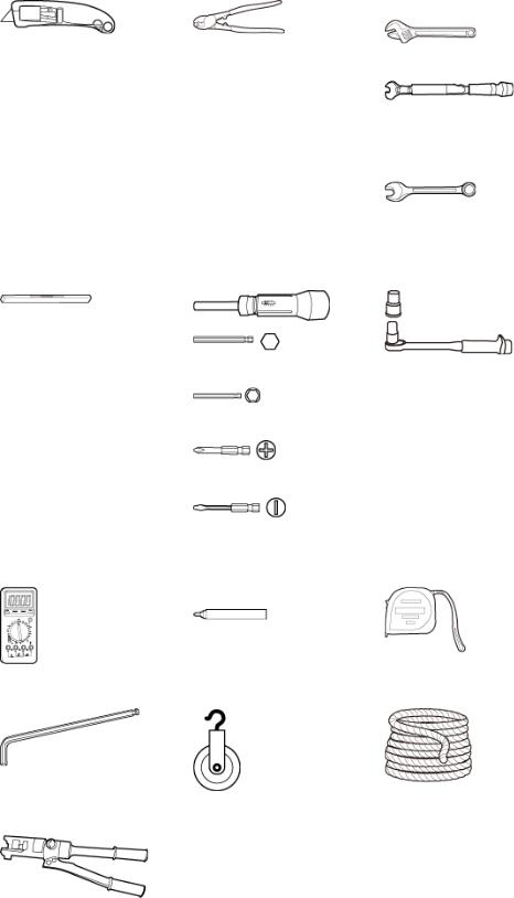
2.2Tools and Instruments
You must prepare the following tools and instruments before the installation.
Hammer drill (a φ12 bit) |
ESD gloves |
Vacuum cleaner |
|
|
|
Heat gun |
Phillips screwdriver (M3 to |
Flat-head screwdriver (M3 to |
|
M6) |
M6) |
|
|
|
Rubber mallet |
COAX crimping tool |
Wire stripper |
|
|
|
Issue DraftA (2015-05-30) |
Huawei Proprietary and Confidential |
3 |
|
Copyright © Huawei Technologies Co., Ltd. |
|
RRU3249 |
|
|
|
Installation Guide |
|
2 Installation Preparations |
|
|
|
|
|
|
Utility knife |
Cable cutter |
Adjustable wrench (size ≥32 |
|
|
|
mm [1.26 in.]) |
|
|
|
Torque wrench |
|
|
|
Size: 18 mm (0.71 in.) and 32 |
|
|
|
mm (1.26 in.) |
|
|
|
Combination wrench |
|
|
|
Size: 18 mm (0.71 in.) and 32 |
|
|
|
mm (1.26 in.) |
|
|
|
|
|
Level |
Torque screwdriver |
Torque socket |
|
|
5 mm |
|
|
|
5 mm |
|
|
|
(M3 to M6) |
|
|
|
(M3 to M6) |
|
|
|
|
|
|
Multimeter |
Marker (diameter ≤ 10 mm |
Measuring tape |
|
|
[0.39 in.]) |
|
|
|
|
|
|
Inner hexagon wrench |
Fixed pulley |
Lifting sling |
|
5 mm |
|
|
|
|
|
|
|
Hydraulic pliers |
- |
- |
|
|
|
|
|
|
|
|
Issue DraftA (2015-05-30) |
Huawei Proprietary and Confidential |
4 |
|
Copyright © Huawei Technologies Co., Ltd. |
|

RRU3249 |
|
Installation Guide |
2 Installation Preparations |
2.3 Skills and Requirements for Onsite Personnel
Onsite personnel must be qualified and trained. Before performing any operation, onsite personnel must be familiar with correct operation methods and safety precautions.
Before the installation, pay attention to the following items:
•The customer's technical engineers must be trained by Huawei and be familiar with the proper installation and operation methods.
•The number of onsite personnel depends on the engineering schedule and installation environment. Generally, only three to five onsite personnel are necessary.
Issue DraftA (2015-05-30) |
Huawei Proprietary and Confidential |
5 |
|
Copyright © Huawei Technologies Co., Ltd. |
|

RRU3249 |
|
Installation Guide |
3 Information About the Installation |
3Information About the Installation
About This Chapter
Before installing an RRU, you must be familiar with its exterior, ports, indicators, installation options and installation clearance requirements.
3.1 RRU Exterior
This section describes the exterior and dimensions of an RRU.
3.2 RRU Ports
This section describes ports on the RRU panels. An RRU has a bottom panel, cabling cavity panel, and indicator panel.
3.3 RRU Indicators
This section describes six indicators on an RRU. They indicate the running status of the RRU.
3.4 Installation Options
This section describes RRU installation options. RRU installation supports the centralized mode.
3.5 Installation Clearance Requirements of an RRU
This section describes the requirements for the installation clearance of multiple RRUs and the requirements for the installation spacing between RRUs.
Issue DraftA (2015-05-30) |
Huawei Proprietary and Confidential |
6 |
|
Copyright © Huawei Technologies Co., Ltd. |
|
RRU3249 |
|
Installation Guide |
3 Information About the Installation |
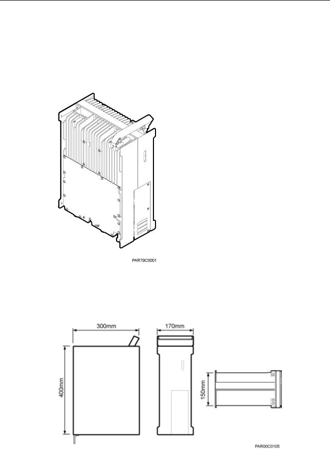
3.1 RRU Exterior
This section describes the exterior and dimensions of an RRU.
Figure 3-1 shows the exterior of an RRU.
Figure 3-1 RRU exterior
Figure 3-2 shows RRU dimensions.
Figure 3-2 RRU dimensions
Issue DraftA (2015-05-30) |
Huawei Proprietary and Confidential |
7 |
|
Copyright © Huawei Technologies Co., Ltd. |
|
RRU3249 |
|
Installation Guide |
3 Information About the Installation |
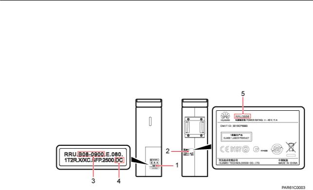
You can obtain the RRU frequency band and power supply information from the configuration label on the cover plate and obtain the RRU name from the nameplate on the side of RRU that accommodates the conversion bracket. Figure 3-3 shows the positions of the configuration label and nameplate on the RRU.
 NOTE
NOTE
The actual label and nameplate may differ from what is shown in the figure.
Figure 3-3 Positions of the label and nameplate
(1) |
Configuration label |
(2) |
Nameplate |
(3) Frequency band |
(4) |
Power supply module |
(5) |
Module name |
- |
3.2 RRU Ports
This section describes ports on the RRU panels. An RRU has a bottom panel, cabling cavity panel, and indicator panel.
Figure 3-4 shows the ports on the RRU panels.
Issue DraftA (2015-05-30) |
Huawei Proprietary and Confidential |
8 |
|
Copyright © Huawei Technologies Co., Ltd. |
|

RRU3249 |
|
Installation Guide |
3 Information About the Installation |
Figure 3-4 Ports on the RRU panels
Table 3-1 describes ports and indicators on the RRU panels.
Table 3-1 Ports and indicators on the RRU panels
Item |
Silkscreen |
Remarks |
|
|
|
|
|
(1) Bottom ports |
ANT_TX/RXA |
TX/RX port A, supporting RET signal |
|
|
|
transmission |
|
|
|
|
|
|
ANT_TX/RXB |
TX/RX port B, supporting RET signal |
|
|
|
transmission |
|
|
|
|
|
|
EXT_ALM |
Alarm monitoring port used for monitoring |
|
|
|
one RS485 signal and two dry contact signals |
|
|
|
|
|
|
RET |
Communication port for the RET antenna, |
|
|
|
supporting RET signal transmission |
|
|
|
|
|
(2) Ports in the cabling |
RTN(+) |
Power supply socket, for details about RRU |
|
cavity |
|
power cable experience and specifications, |
|
NEG(-) |
|||
|
see RRU Power Cable. |
||
|
|
||
|
|
|
|
|
CPRI0 |
Optical/electrical port 0, connected to the |
|
|
|
BBU |
|
|
|
|
Issue DraftA (2015-05-30) |
Huawei Proprietary and Confidential |
9 |
|
Copyright © Huawei Technologies Co., Ltd. |
|
RRU3249 |
|
|
|
Installation Guide |
|
3 Information About the Installation |
|
|
|
|
|
|
Item |
Silkscreen |
Remarks |
|
|
|
|
|
|
CPRI1 |
Optical/electrical port 1, connected to the |
|
|
|
BBU |
|
|
|
|
|
(3) Indicator |
RUN |
For details, see 3.3 RRU Indicators. |
|
|
|
|
|
|
ALM |
|
|
|
|
|
|
|
ACT |
|
|
|
|
|
|
|
VSWR |
|
|
|
|
|
|
|
CPRI0 |
|
|
|
|
|
|
|
CPRI1 |
|
|
|
|
|
 NOTE
NOTE
•The port for transmitting RET signals is determined by the software.
•Connect the CPRI0 port to the BBU by default in the single-mode scenario.
3.3RRU Indicators
This section describes six indicators on an RRU. They indicate the running status of the RRU. For detailed positions of RRU indicators, see 3.2 RRU Ports.
Table 3-2 describes RRU indicators.
Table 3-2 RRU Indicators
Indicator |
Color |
Status |
Meaning |
|
|
|
|
RUN |
Green |
Steady on |
The power input is available, but the board is |
|
|
|
faulty. |
|
|
|
|
|
|
Steady off |
No power input is available or the board is |
|
|
|
faulty. |
|
|
|
|
|
|
Blinking (on for |
The board is running properly. |
|
|
1s and off for 1s) |
|
|
|
|
|
|
|
Blinking (on for |
The board software is being loaded or the |
|
|
0.125s and off for |
board is not working. |
|
|
0.125s) |
|
|
|
|
|
ALM |
Red |
Steady on |
Alarms are generated, and the module must |
|
|
|
be replaced. |
|
|
|
|
Issue DraftA (2015-05-30) |
Huawei Proprietary and Confidential |
10 |
|
Copyright © Huawei Technologies Co., Ltd. |
|
RRU3249 |
|
|
|
|
Installation Guide |
|
|
3 Information About the Installation |
|
|
|
|
|
|
|
Indicator |
Color |
Status |
Meaning |
|
|
|
|
|
|
|
|
Blinking (on for |
Alarms are generated. The alarms may be |
|
|
|
1s and off for 1s) |
caused by faults on the related board or ports. |
|
|
|
|
Therefore, you need to locate the fault before |
|
|
|
|
deciding whether to replace the module. |
|
|
|
|
|
|
|
|
Steady off |
No alarms are generated. |
|
|
|
|
|
|
ACT |
Green |
Steady on |
The board is working properly when TX |
|
|
|
|
channels are enabled or software is being |
|
|
|
|
loaded to a board that is not started. |
|
|
|
|
|
|
|
|
Blinking (on for |
The board is running with TX channels |
|
|
|
1s and off for 1s) |
disabled. |
|
|
|
|
|
|
VSWR |
Red |
Steady off |
No voltage standing wave ratio (VSWR) |
|
|
|
|
alarm is generated. |
|
|
|
|
|
|
|
|
Blinking (on for |
VSWR alarms are generated on the |
|
|
|
1s and off for 1s) |
ANT_TX/RXB port. |
|
|
|
|
|
|
|
|
Steady on |
VSWR alarms are generated on the |
|
|
|
|
ANT_TX/RXA port. |
|
|
|
|
|
|
|
|
Blinking (on for |
VSWR alarms are generated on the |
|
|
|
0.125s and off for |
ANT_TX/RXA and ANT_TX/RXB ports. |
|
|
|
0.125s) |
|
|
|
|
|
|
|
CPRI0 |
Red and |
Steady green |
The CPRI link is running properly. |
|
|
green |
|
|
|
|
Steady red |
An optical module fails to receive or transmit |
|
|
|
|
||
|
|
|
|
signals possibly because the optical module |
|
|
|
|
is faulty or the optical fiber is broken. |
|
|
|
|
|
|
|
|
Blinking red (on |
The CPRI link is out of lock because of faults |
|
|
|
for 1s and off for |
on the mutual lock of dual-mode clock |
|
|
|
1s) |
sources or mismatched data rates on CPRI |
|
|
|
|
ports. |
|
|
|
|
|
|
|
|
Steady off |
The optical module cannot be detected or is |
|
|
|
|
powered off. |
|
|
|
|
|
|
CPRI1 |
Red and |
Steady green |
The CPRI link is running properly. |
|
|
green |
|
|
|
|
Steady red |
An optical module fails to receive or transmit |
|
|
|
|
||
|
|
|
|
signals possibly because the optical module |
|
|
|
|
is faulty or the optical fiber is broken. |
|
|
|
|
|
|
|
|
Blinking red (on |
The CPRI link is out of lock because of faults |
|
|
|
for 1s and off for |
on the mutual lock of dual-mode clock |
|
|
|
1s) |
sources or mismatched data rates on CPRI |
|
|
|
|
ports. |
|
|
|
|
|
|
|
|
Steady off |
The optical module cannot be detected or is |
|
|
|
|
powered off. |
|
|
|
|
|
Issue DraftA (2015-05-30) |
Huawei Proprietary and Confidential |
11 |
|
Copyright © Huawei Technologies Co., Ltd. |
|
RRU3249 |
|
Installation Guide |
3 Information About the Installation |
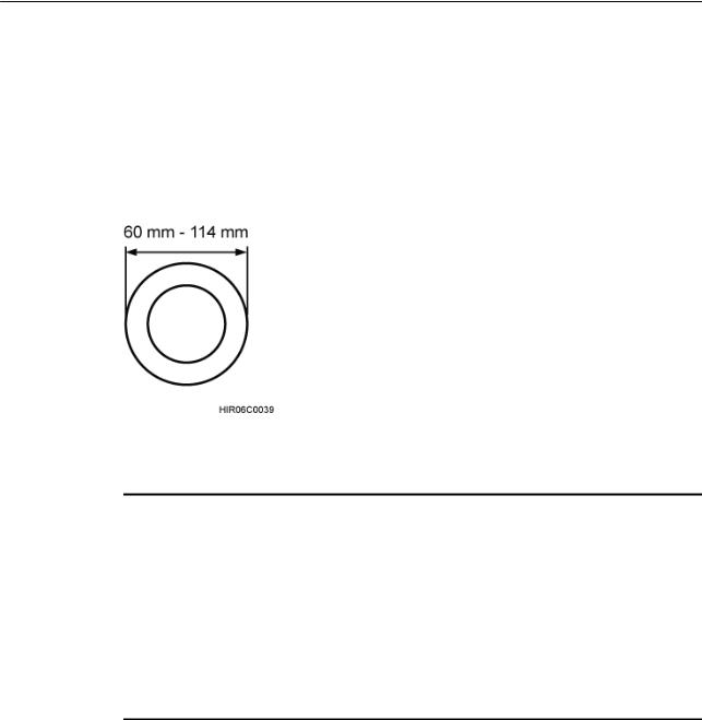
3.4 Installation Options
This section describes RRU installation options. RRU installation supports the centralized mode.
Figure 3-5 shows the diameter of a pole for installing an RRU.
Figure 3-5 Diameter of a pole
 NOTICE
•The diameter of a pole for installing an RRU ranges from 60 mm (2.36 in.) to 114 mm (4.49 in.). The recommended diameter is 80 mm (3.15 in.).
•When the diameter of a pole ranges from 60 mm (2.36 in.) to 76 mm (2.99 in.), a maximum of three RRUs can be installed on the pole and the side-mounted installation is recommended.
•Only a pole whose diameter ranges from 76 mm (2.99 in.) to 114 mm (4.49 in.) supports more than three RRUs.
•The recommended thickness of the pole wall is 3.5 mm (0.14 in.) or above.
Figure 3-6 shows two RRUs installed in centralized mode.
Figure 3-7 shows three RRUs installed in centralized mode.
Issue DraftA (2015-05-30) |
Huawei Proprietary and Confidential |
12 |
|
Copyright © Huawei Technologies Co., Ltd. |
|
RRU3249 |
|
Installation Guide |
3 Information About the Installation |
Figure 3-6 Two RRUs installed in centralized mode
Figure 3-7 Three RRUs installed in centralized mode
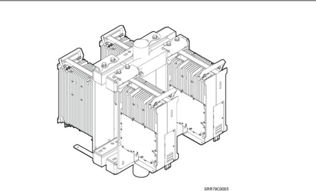
Figure 3-8 shows four RRUs installed in centralized mode.
Issue DraftA (2015-05-30) |
Huawei Proprietary and Confidential |
13 |
|
Copyright © Huawei Technologies Co., Ltd. |
|
RRU3249 |
|
Installation Guide |
3 Information About the Installation |
Figure 3-8 Four RRUs installed in centralized mode
 NOTE
NOTE
For details about how to install RRUs on an IFS06, see DBS3900 (ICR) Installation Guide.
3.5 Installation Clearance Requirements of an RRU
This section describes the requirements for the installation clearance of multiple RRUs and the requirements for the installation spacing between RRUs.
3.5.1 Installation Clearance for Multiple RRUs
This section describes the recommended and minimum installation clearance for multiple RRUs.
Recommended Installation Clearance for Multiple RRUs Installed in Centralized Mode
Figure 3-9 shows the recommended installation clearance for multiple RRUs installed in centralized mode.
Issue DraftA (2015-05-30) |
Huawei Proprietary and Confidential |
14 |
|
Copyright © Huawei Technologies Co., Ltd. |
|

RRU3249 |
|
Installation Guide |
3 Information About the Installation |
|
Figure 3-9 Recommended installation clearance for multiple RRUs installed in centralized mode |
Minimum Installation Clearance for Multiple RRUs Installed in Centralized Mode
Figure 3-10 shows the minimum installation clearance for multiple RRUs installed in centralized mode.
Figure 3-10 Minimum installation clearance for multiple RRUs installed in centralized mode
Issue DraftA (2015-05-30) |
Huawei Proprietary and Confidential |
15 |
|
Copyright © Huawei Technologies Co., Ltd. |
|
RRU3249 |
|
Installation Guide |
3 Information About the Installation |
3.5.2 Installation Spacing Between RRUs
This section describes the horizontal and vertical spacing between RRUs.
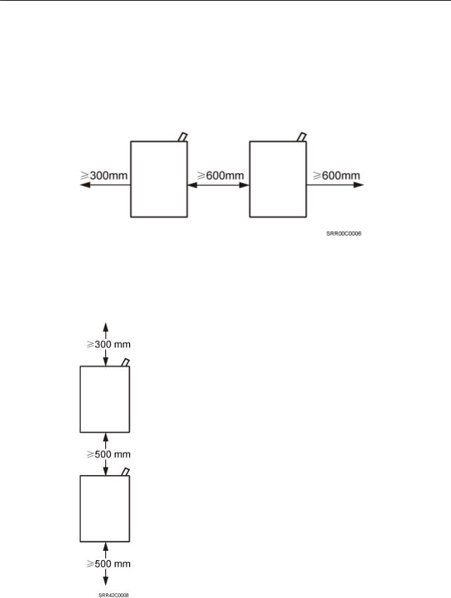
Figure 3-11 shows the recommended horizontal spacing between RRUs.
Figure 3-11 Recommended horizontal spacing between RRUs
Figure 3-12 shows the recommended vertical spacing between RRUs.
Figure 3-12 Recommended vertical spacing between RRUs
Issue DraftA (2015-05-30) |
Huawei Proprietary and Confidential |
16 |
|
Copyright © Huawei Technologies Co., Ltd. |
|
Loading...