


BTS3911B
V100R010C10
Installation Guide
Issue: Draft A
Date: 2015-01-20
HUAWEI TECHNOLOGIES CO., LTD.
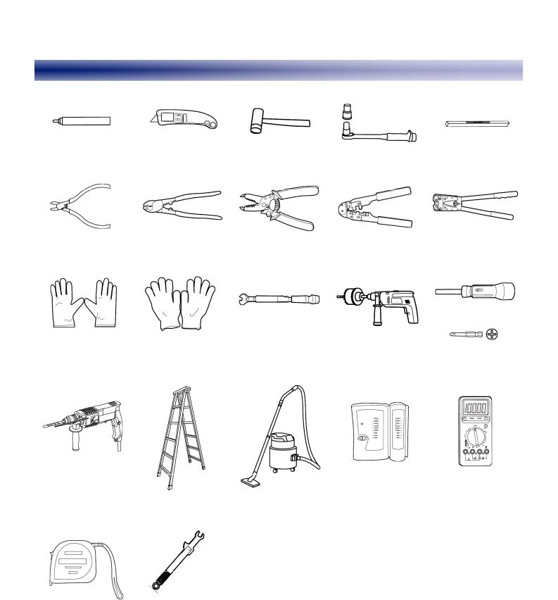
Installation Tools
|
Marker |
|
|
|
|
|
|
|
|
|
Utility knife |
Rubber |
mallet |
Socket wrench (M6) |
Level |
|
|||
|
|
|
|
|
|
|
|
|
|
|
|
|
|
|
|
|
|
|
|
|
Diagonal pliers |
Cable cutter |
Wire |
stripper |
RJ11 crimping tool |
Power cable crimping |
|
||
|
|
|
|
|
|
|
|
tool |
|
|
|
|
|
|
|
|
|
|
|
|
|
|
|
|
|
|
|
Phillips torque |
|
|
|
|
|
|
|
|
|
screwdriver |
|
|
ESD gloves |
Protective gloves |
Torque wrench (bore |
crown saw (Ø60 bore) |
(M4 to M6) |
|
|||
|
|
|
size: 10 mm) |
|
|
|
|||
|
|
|
|
|
|
|
|
|
|
|
|
|
|
|
|
|
|
|
|
|
|
|
|
|
|
|
|
|
|
|
Hammer drill (Ø6, Ø8 |
|
|
|
|
|
Network cable tester |
Multimeter |
|
|
or Ø12 bore) |
Ladder |
Vacuum |
cleaner |
|
||||
|
|
|
|
|
|
|
|
|
|
|
|
|
- |
|
|
|
- |
- |
|
|
Measuring tape |
Torque wrench for |
|
|
|
|
|
|
|
|
|
|
|
|
|
|
|
||
|
SMA connectors |
|
|
|
|
|
|
|
|
|
|
|
|
|
|
|
|
|
|
|
|
|
|
|
|
|
|
|
|
|
|
|
|
|
|
|
Copyright © Huawei Technologies Co., Ltd. 2015. |
|
|
|
|
|
|
|
|
|
|
||
|
|
|
|
|
2 |
|
|
||
|
|
|
|
|
|
All rights reserved. |
|
|
|
|
|
|
|
|
|
|
|
|
|
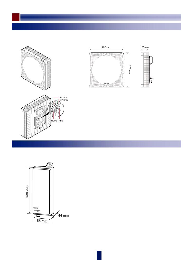
Product Introduction
BTS3911B
The BTS3911B uses internal antennas.
Appearance
b
Ports
Dimensions
Port Description
Port |
|
Description |
Micro |
SD |
Anchor slot for the Micro SD card used for |
|
|
deployment |
Mini U SB |
Port for clock output |
|
RGPS |
Port for clock synchronization |
|
P&E |
Port for transmission and power supply |
|
PSE
Appearance and Dimensions |
Port Description |
||
|
|
|
|
|
Port |
|
Description |
|
- |
|
Power port that supplies power to the PSE |
|
DATA |
|
Data input port that connects to transmission |
|
|
|
equipment of an operator |
|
PoE |
|
PoE output port that connects to the |
|
|
|
BTS3911B |
|
|
|
|
 3
3
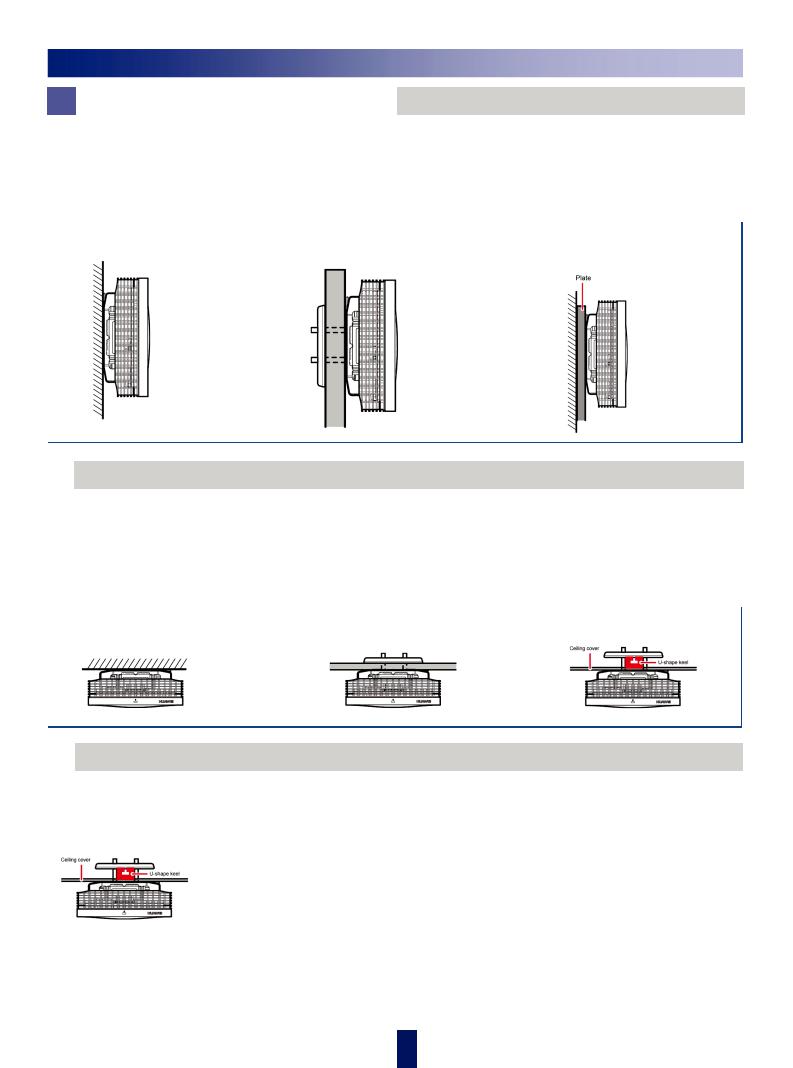
Installation Scenarios
Wall-mounted Installation
•The wall must have a bearing capacity of at least four times the weight of the BTS3911B.
•The screws must be torqued to 1.5 N·m and work properly without causing cracks on the wall.
•The thickness of the wall must be less than t he bolt length (45 mm) to allow for installation through an existing plate.
•If the wall is too thick, use a customer-provided installation plate.
 Ceiling-mounted Installation
•The ceiling (such as concrete ceiling) must ha ve a bearing capacity of at least four times the weight of the BTS3911B.
•The screws must be torqued to 1.5 N·m and work properly without causing cracks on the wall.
•The thickness of the ceiling must be less than the bolt length (45 mm) to allow for installation through an existing plate.
 Keel-mounted Installation
The BTS3911B can be installed on a U-shaped, T-shaped, H-shaped, or other shaped keel, depending on site requirements. The following figure illustrates keel-mounted installation on a ceiling.
 4
4

Clearance Requirements
z For a BTS3911B |
z For a PSE |
|
|
|
|
Installation Environment Requirement s
 Operating Environment Requirements
|
|
|
|
|
|
|
|
|
|
Specifications |
Requirements |
Remarks |
|
|
Operating temperature |
-5 ºC to +40ºC |
- |
|
|
Relative humidity |
5% RH to 95% RH |
- |
|
|
|
|
|
|
|
|
|
-60 m to +1800 m |
The BTS3911B works properly under the condition. |
|
|
|
|
|
|
Altitude |
1800 m to 4000 m |
From the altitude of 1,800 m, the maximum operating |
|
|
|
|
temperature drops by 1ºC each time the altitude increases by |
|
|
|
|
|
220 m. |
|
 Other Requirements
•The BTS3911B cannot be installed near air conditioner outlet or near other heat-generating appliances.
• The BTS3911B cannot be installed near a str ong heat source of any kind.
•The BTS3911B cannot be installed near places where water may leak or drip, such as near outdoor air conditioner units, water pipes, pip elines, and roofs with water leaks or dripping runoff.
•The installation must be protected against rain. No window exists at either side of the wall where the BTS3911B is installed.
•The installation position must be far away from high voltage, highly corrosive devices, flammable or explosive substances, and elec tromagnetic interference.
•The BTS3911B must be installed in a dry, we ll-ventilated, and dustproof place.
•If the BTS3911B is installed in parking areas or basements, the installation position must be well ventilated.
 5
5
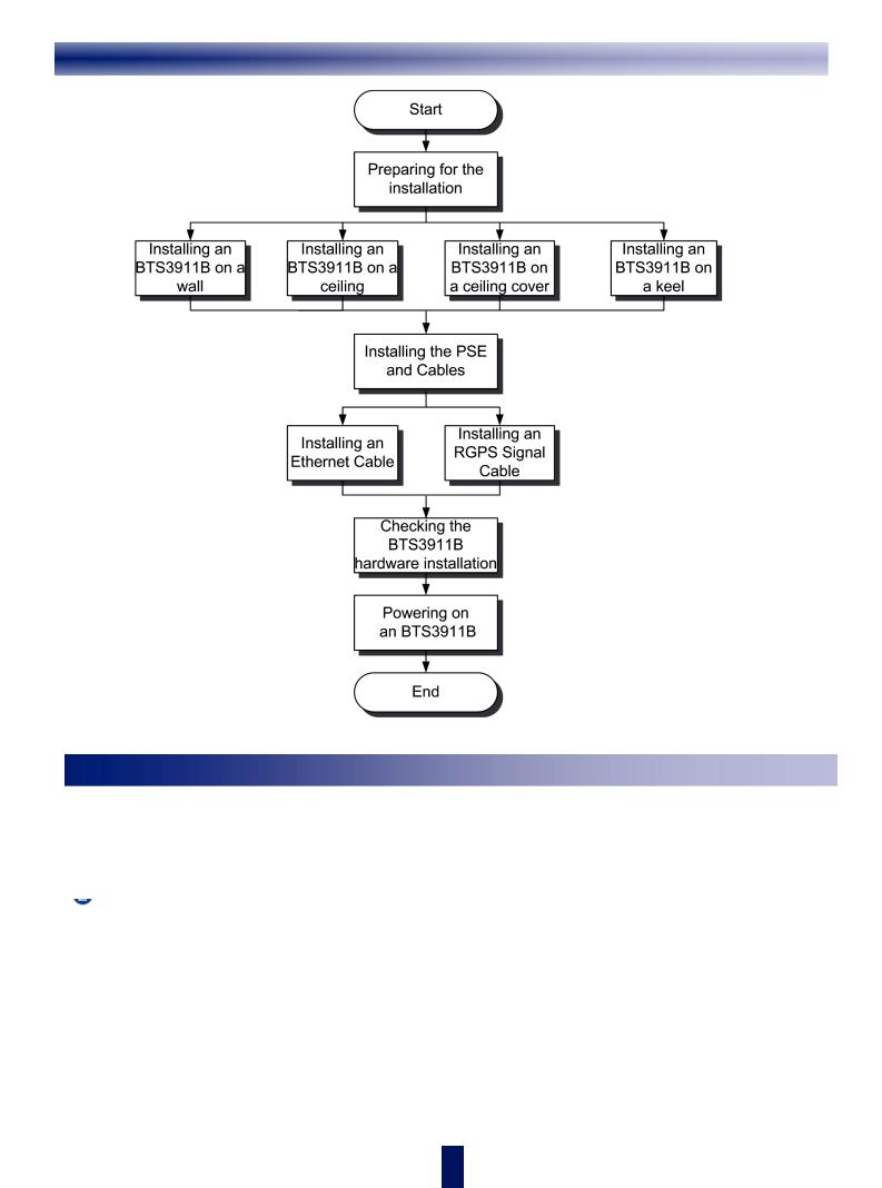
Installation Process
Obtaining the ESN
Before installation, record the ESN, which will e used during commissioning. Before removing the backup ESN label, photograph it.
 Remove the backup ESN label from the BTS3911B packing box.
 Record the ESN by following instructions provided in Appendix 3 and report the ESN to the BTS3911B commissioning personnel. Keep the backup ESN label secure.
 6
6

 Installing a BTS3911B
BTS3911B can be installed on a wall or ceiling directly or by using a plate or keel.
Mounting Kits
z Wallor ceiling-mounted installation |
z Installation on a plate or keel |
|||
(1) |
Mounting bracket |
(1) |
Mounting bracket |
|
(2) |
V clamp |
|||
(2) |
Screws (M3.5X35) |
|||
(3) |
Bolt (M4X35) |
|||
(3) |
Plastic expansion sleeve |
|||
(4) |
Bolt (M4X36) |
|||
(4) |
Flat washer |
|||
|
|
|||
Installing a BTS3911B on a Wall
Mark anchor points |
|
Install mounting kits |
Install the BTS3911B on the |
|
|
|
wall |
|
|
|
|
|
|
|
|
(1) Wall (2) Mounting bracket
(3) Anchor points
Installing a BTS3911B on a Ceiling
Mark anchor points |
Install mounting kits |
Install the BTS3911B on |
|
the ceiling |
|||
|
|
||
|
|
|
(1) Wall (2) Mounting bracket
(3) Anchor points
 7
7

Installing a BTS3911B on a Plate
On a ceiling plate (for example, daughter board on the ceiling) capable of being screwed
Mark anchor points |
Install mounting kits |
(1)Plate
(2)Mounting bracket
(3)Anchor points
Install the BTS3911B on the ceiling plate
On a ceiling plate (for example, gypsum board) incapable of being screwed
Use a crown saw to drill a hole (diameter: 60-65 mm)
Lead the U-shaped metal plate through the hole on the ceiling
Secure mounting kits to the ceiling plate |
Install the BTS3911B on the ceiling plate |
|
|
|
|
 8
8

Installing a BTS3911B on a Keel |
|
||
Mark anchor points |
Install mou nting kits |
Install the BTS3911B on the plate |
|
Plate |
U-shaped keel |
|
|
U-shaped metal plate
Installing the PSE and Its Cables
The PSE can be installed only on an indoor wall .
Installing the PSE |
Installing Cables |
Power port
(1) Ethernet cable
(2) PSE power cable
Installing the BTS3911B Cables
z Installing an Ethernet cable z Installing an RGPS signal cable
 9
9
 Loading...