


 Loading...
AP6050DN & AP6150DN
Hardware Installation and
Maintenance Guide
Issue 03
Date 2016-09-30
HUAWEI TECHNOLOGIES CO., LTD.

Copyright © Huawei Technologies Co., Ltd. 2016. All rights reserved.
No part of this document may be reproduced or transmitted in any form or by any means without prior written consent of Huawei Technologies Co., Ltd.
Trademarks and Permissions


 and other Huawei trademarks are trademarks of Huawei Technologies Co., Ltd.
All other trademarks and trade names mentioned in this document are the property of their respective holders.
Notice
The purchased products, services and features are stipulated by the contract made between Huawei and the customer. All or part of the products, services and features described in this document may not be within the purchase scope or the usage scope. Unless otherwise specified in the contract, all statements, information, and recommendations in this document are provided "AS IS" without warranties, guarantees or representations of any kind, either express or implied.
The information in this document is subject to change without notice. Every effort has been made in the preparation of this document to ensure accuracy of the contents, but all statements, information, and recommendations in this document do not constitute a warranty of any kind, express or implied.
Huawei Technologies Co., Ltd.
Address: |
Huawei Industrial Base |
|
Bantian, Longgang |
|
Shenzhen 518129 |
|
People's Republic of China |
Website: |
http://www.huawei.com |
Email: |
support@huawei.com |
Issue 03 (2016-09-30) |
Huawei Proprietary and Confidential |
i |
|
Copyright © Huawei Technologies Co., Ltd. |
|
AP6050DN & AP6150DN |
About This Document |
Hardware Installation and Maintenance Guide |
About This Document
Intended Audience
This document describes hardware features of the AP6050DN and AP6150DN and provides basic installation methods.
This document is intended for:
•Network planning engineers
•Hardware installation engineers
•Commissioning engineers
•Onsite maintenance engineers
•System maintenance engineers
Symbol Conventions
The symbols that may be found in this document are defined as follows.
Symbol |
|
Description |
|
|
|
|
|
|
|
|
Indicates an imminently hazardous situation |
|
|
|
which, if not avoided, will result in death or |
|
|
|
serious injury. |
|
|
|
|
|
|
|
Indicates a potentially hazardous situation |
|
|
|
which, if not avoided, could result in death |
|
|
|
or serious injury. |
|
|
||
|
|
|
|
|
|
|
Indicates a potentially hazardous situation |
|
|
|
which, if not avoided, may result in minor |
|
|
|
or moderate injury. |
|
|
||
|
|
|
|
|
|
|
Indicates a potentially hazardous situation |
|
|
|
which, if not avoided, could result in |
|
|
|
equipment damage, data loss, performance |
|
|
||
|
|
|
deterioration, or unanticipated results. |
|
|
|
NOTICE is used to address practices not |
|
|
|
related to personal injury. |
|
|
|
|
Issue 03 (2016-09-30) |
Huawei Proprietary and Confidential |
ii |
|
Copyright © Huawei Technologies Co., Ltd. |
|

AP6050DN & AP6150DN |
About This Document |
||||
Hardware Installation and Maintenance Guide |
|||||
|
|
|
|
|
|
|
Symbol |
Description |
|||
|
|
|
|
|
|
|
|
|
|
NOTE |
Calls attention to important information, |
|
|
|
|
||
|
|
|
|
||
|
|
|
|
|
best practices and tips. |
|
|
|
|
|
NOTE is used to address information not |
|
|
|
|
|
related to personal injury, equipment |
|
|
|
|
|
damage, and environment deterioration. |
|
|
|
|
|
|
Change History
Changes between document issues are cumulative. The latest document issue contains all changes made in previous issues.
Issue 03 (2016-09-30)
This version has the following updates:
The following information is modified:
•1.1 Device Structure
•2.6 Cable Connection
Issue 02 (2016-07-22)
This version has the following updates:
The following information is modified:
•1.4 Ordering Information
Issue 01 (2016-05-31)
Initial commercial release
Issue 03 (2016-09-30) |
Huawei Proprietary and Confidential |
iii |
|
Copyright © Huawei Technologies Co., Ltd. |
|

AP6050DN & AP6150DN |
|
Hardware Installation and Maintenance Guide |
Contents |
Contents
About This Document..................................................................................................................... |
|
ii |
|
1 Product Overview.......................................................................................................................... |
|
1 |
|
1.1 |
Device Structure............................................................................................................................................................. |
|
2 |
1.2 |
Indicator Description...................................................................................................................................................... |
|
3 |
1.3 |
Basic Specifications........................................................................................................................................................ |
|
5 |
1.4 |
Ordering Information...................................................................................................................................................... |
|
6 |
2 AP Installation............................................................................................................................... |
|
7 |
|
2.1 |
Preparing for Installation................................................................................................................................................ |
|
8 |
2.2 |
Installation Flowchart..................................................................................................................................................... |
|
9 |
2.3 |
Unpacking the Equipment............................................................................................................................................ |
|
10 |
2.4 |
Determining the Installation Position........................................................................................................................... |
|
11 |
2.5 |
Installing the AP........................................................................................................................................................... |
|
12 |
2.5.1 Installing the Device on a Wall.................................................................................................................................. |
|
12 |
|
2.5.2 Installing the device on a Ceiling.............................................................................................................................. |
|
13 |
|
2.5.3 Installing the device on a T-rail................................................................................................................................. |
|
14 |
|
2.6 |
Cable Connection......................................................................................................................................................... |
|
16 |
2.7 |
Connecting the Security Lock...................................................................................................................................... |
|
18 |
2.8 |
Checking the Device After Installation........................................................................................................................ |
18 |
|
2.9 |
Powering on the AP...................................................................................................................................................... |
|
19 |
3 Logging In to the Device............................................................................................................ |
|
20 |
|
3.1 |
Logging In to the Device Using STelnet/Telnet........................................................................................................... |
21 |
|
3.2 |
Logging In to the Device Through the Web System (Applicable to the Fat AP Only)................................................ |
22 |
|
3.3 |
Logging In to the Device Through the Console Port.................................................................................................... |
22 |
|
4 Hardware Failures....................................................................................................................... |
|
24 |
|
4.1 |
A Device Fails to Be Powered On................................................................................................................................ |
|
25 |
5 Appendix....................................................................................................................................... |
|
27 |
|
5.1 |
On-site Cable Assembly and Installation..................................................................................................................... |
28 |
|
5.1.1 Cable Assembly Precautions..................................................................................................................................... |
|
28 |
|
5.1.2 Assembling Power Cables......................................................................................................................................... |
|
29 |
|
5.1.3 Assembling Ethernet Cables...................................................................................................................................... |
|
37 |
|
5.1.4 Installing Cable Accessories...................................................................................................................................... |
|
51 |
|
Issue 03 (2016-09-30) |
Huawei Proprietary and Confidential |
iv |
|
|
Copyright © Huawei Technologies Co., Ltd. |
|
|

AP6050DN & AP6150DN |
|
|
Hardware Installation and Maintenance Guide |
Contents |
|
5.1.5 Replacing the Mold of the Crimping Tool................................................................................................................. |
67 |
|
5.2 |
Environmental Requirements for Device Operation.................................................................................................... |
70 |
5.2.1 Environmental Requirements for an Equipment Room............................................................................................ |
70 |
|
5.2.2 Requirements for Power Supply................................................................................................................................ |
78 |
|
5.3 |
Equipment Grounding Specifications........................................................................................................................... |
81 |
5.3.1 General Grounding Specifications............................................................................................................................. |
81 |
|
5.3.2 Grounding Specifications for an Equipment Room.................................................................................................. |
81 |
|
5.3.3 Grounding Specifications for Devices....................................................................................................................... |
81 |
|
5.3.4 Grounding Specifications for Communications Power Supply................................................................................. |
82 |
|
5.3.5 Grounding Specifications for Signal Cables............................................................................................................. |
83 |
|
5.3.6 Specifications for Laying Out Grounding Cables..................................................................................................... |
83 |
|
5.4 |
Engineering Labels for Cables..................................................................................................................................... |
84 |
5.4.1 Introduction to Labels................................................................................................................................................ |
84 |
|
5.4.2 Engineering Labels for Optical Fibers....................................................................................................................... |
92 |
|
5.4.3 Engineering Labels for Network Cables................................................................................................................... |
95 |
|
5.4.4 Engineering Labels for User Cables.......................................................................................................................... |
96 |
|
5.4.5 Engineering Labels for Power Cables....................................................................................................................... |
97 |
|
5.5 |
Guide to Using Optical Modules................................................................................................................................ |
100 |
5.6 |
Fault Tag..................................................................................................................................................................... |
103 |
5.7 |
Installation Checklist.................................................................................................................................................. |
104 |
Issue 03 (2016-09-30) |
Huawei Proprietary and Confidential |
v |
|
Copyright © Huawei Technologies Co., Ltd. |
|

AP6050DN & AP6150DN |
1 Product Overview |
Hardware Installation and Maintenance Guide |
1Product Overview
About This Chapter
The AP6050DN and AP6150DN support MU-MIMO (4SU-3MU), provide comprehensive service support capabilities, and feature high reliability, high security, simple network deployment, automatic AC discovery and configuration, as well as real-time management and maintenance, which meet network deployment requirements. The APs comply with the 802.11ac Wave2 protocol and can provide up to 2.53 Gbit/s theoretical bandwidth for wireless users, greatly improving user experience.
The AP6050DN and AP6150DN are applicable to mobile office, high-density, elementary education, and higher education scenarios for providing high-performance wireless services for users. The APs can be deployed flexibly based on site environments.
1.1Device Structure
1.2Indicator Description
1.3Basic Specifications
1.4Ordering Information
Issue 03 (2016-09-30) |
Huawei Proprietary and Confidential |
1 |
|
Copyright © Huawei Technologies Co., Ltd. |
|
AP6050DN & AP6150DN |
1 Product Overview |
Hardware Installation and Maintenance Guide |
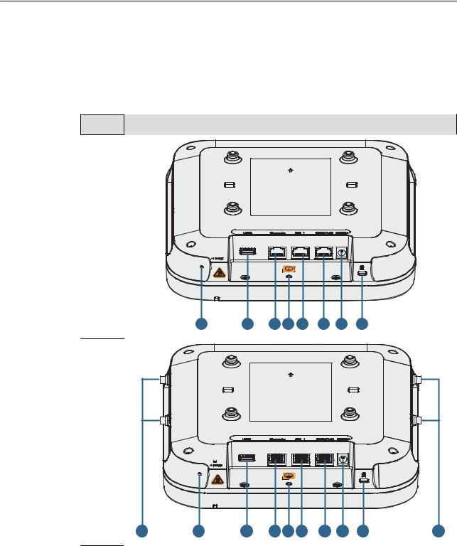
1.1 Device Structure
Table 1-1 describes the appearances of the AP6050DN and AP6150DN.
Table 1-1 Appearances of the AP6050DN and AP6150DN
Model |
Appearance |
|
|
|
|
|
|
|
|
|
AP6050 |
|
|
|
|
|
|
|
|
|
|
DN |
|
|
|
|
|
|
|
|
|
|
|
|
1 |
2 |
3 |
4 |
5 |
6 |
7 |
8 |
|
AP6150 |
|
|
|
|
|
|
|
|
|
|
DN |
|
|
|
|
|
|
|
|
|
|
|
9 |
1 |
2 |
3 |
4 |
5 |
6 |
7 |
8 |
9 |
Table 1-2 describes interfaces on the AP6050DN and AP6150DN.
Issue 03 (2016-09-30) |
Huawei Proprietary and Confidential |
2 |
|
Copyright © Huawei Technologies Co., Ltd. |
|

AP6050DN & AP6150DN |
|
1 Product Overview |
|
Hardware Installation and Maintenance Guide |
|||
|
Table 1-2 Interface description |
|
|
|
|
|
|
|
No. |
Name |
Description |
|
|
|
|
|
1 |
Default |
Reset button: restores factory settings and restarts the |
|
|
|
device if you hold down the button more than 3 seconds. |
|
|
|
|
|
2 |
USB port |
Connects to a USB flash drive to extend the storage space |
|
|
|
of the AP, and provides a maximum of 2.5 W power. |
|
|
|
|
|
3 |
CONSOLE |
Connects to a maintenance terminal for AP configuration |
|
|
|
and management. |
|
|
|
|
|
4 |
Ground screw |
Connects the AP to a ground cable. |
|
|
|
|
|
5 |
GE1 |
10/100/1000M port: connects to the wired Ethernet. |
|
|
|
|
|
6 |
GE0/PoE |
10/100/1000M port: connects to the wired Ethernet. The |
|
|
|
port can connect to a PoE power supply device to provide |
|
|
|
power for APs. |
|
|
|
|
|
7 |
DC 12V |
Connects to PoE or DC power supply. |
|
|
|
NOTE |
|
|
|
When the AP uses the DC power supply, use a power adapter for |
|
|
|
power supply; otherwise, the AP may be damaged. |
|
|
|
|
|
8 |
Security slot |
Connects to a security lock. |
|
|
|
|
|
9 |
Antenna port |
Connects to an external antenna for transmitting and |
|
|
|
receiving service signals. The ports are provided only on |
|
|
|
APs using external antennas. |
|
|
|
|
1.2 Indicator Description
The AP6050DN and AP6150DN provide only one indicator, as shown in Figure 1-1.
 NOTE
NOTE
Indicator colors may vary slightly at different temperature.
Figure 1-1 Indicator
Indicator
Issue 03 (2016-09-30) |
Huawei Proprietary and Confidential |
3 |
|
Copyright © Huawei Technologies Co., Ltd. |
|
AP6050DN & AP6150DN |
|
|
1 Product Overview |
||
Hardware Installation and Maintenance Guide |
|
|
|||
|
Table 1-3 Indicator description |
|
|
||
|
|
|
|
|
|
|
Type |
|
Color |
Status |
Description |
|
|
|
|
|
|
|
Default status after |
|
Green |
Steady on |
The AP is just |
|
power-on |
|
|
|
powered on and the |
|
|
|
|
|
software is not |
|
|
|
|
|
started yet. |
|
|
|
|
|
|
|
Software startup |
|
Green |
Steady on after |
After the system is |
|
status |
|
|
blinking once |
reset and starts |
|
|
|
|
|
loading the software, |
|
|
|
|
|
the indicator blinks |
|
|
|
|
|
green once. Until the |
|
|
|
|
|
software is loaded |
|
|
|
|
|
and started, the |
|
|
|
|
|
indicator remains |
|
|
|
|
|
steady green. |
|
|
|
|
|
|
|
Running status |
|
Green |
Blinking once every |
• The system is |
|
|
|
|
2s (0.5 Hz) |
running properly, |
|
|
|
|
|
the Ethernet |
|
|
|
|
|
connection is |
|
|
|
|
|
normal, and |
|
|
|
|
|
STAs are |
|
|
|
|
|
associated with |
|
|
|
|
|
the AP. |
|
|
|
|
|
• The system |
|
|
|
|
|
enters the Uboot |
|
|
|
|
|
CLI. |
|
|
|
|
|
|
|
|
|
|
Blinking once every |
The system is |
|
|
|
|
5s (0.2 Hz) |
running properly, the |
|
|
|
|
|
Ethernet connection |
|
|
|
|
|
is normal, and no |
|
|
|
|
|
STA is associated |
|
|
|
|
|
with the AP. The |
|
|
|
|
|
system is in low |
|
|
|
|
|
power consumption |
|
|
|
|
|
state. |
|
|
|
|
|
|
Issue 03 (2016-09-30) |
Huawei Proprietary and Confidential |
4 |
|
Copyright © Huawei Technologies Co., Ltd. |
|
AP6050DN & AP6150DN |
|
|
1 Product Overview |
||
Hardware Installation and Maintenance Guide |
|
|
|||
|
|
|
|
|
|
|
Type |
|
Color |
Status |
Description |
|
|
|
|
|
|
|
Alarm |
|
Green |
Blinking once every |
• The software is |
|
|
|
|
0.25s (4 Hz) |
being upgraded. |
|
|
|
|
|
• After the |
|
|
|
|
|
software is |
|
|
|
|
|
loaded and |
|
|
|
|
|
started, the AP |
|
|
|
|
|
requests to go |
|
|
|
|
|
online on the AC |
|
|
|
|
|
and maintains |
|
|
|
|
|
this state until it |
|
|
|
|
|
goes online |
|
|
|
|
|
successfully on |
|
|
|
|
|
the AC (before |
|
|
|
|
|
the CAPWAP |
|
|
|
|
|
link is |
|
|
|
|
|
established). |
|
|
|
|
|
• The AP fails to |
|
|
|
|
|
go online on the |
|
|
|
|
|
AC (the |
|
|
|
|
|
CAPWAP link |
|
|
|
|
|
disconnects). |
|
|
|
|
|
|
|
Fault |
|
Red |
Steady on |
A fault that affects |
|
|
|
|
|
services has |
|
|
|
|
|
occurred, such as a |
|
|
|
|
|
DRAM detection |
|
|
|
|
|
failure or system |
|
|
|
|
|
software loading |
|
|
|
|
|
failure. The fault |
|
|
|
|
|
cannot be |
|
|
|
|
|
automatically |
|
|
|
|
|
rectified and must be |
|
|
|
|
|
rectified manually. |
|
|
|
|
|
|
1.3 Basic Specifications
Table 1-4 provides basic specifications of the AP6050DN and AP6150DN.
Table 1-4 Basic specifications
Item |
|
Description |
|
|
|
Technical |
Dimensions (H x |
53 mm x 220 mm x 220 mm |
specifications |
W x D) |
|
|
|
|
|
Weight |
• AP6050DN: 1.20 kg |
|
|
• AP6150DN: 1.29 kg |
|
|
|
Issue 03 (2016-09-30) |
Huawei Proprietary and Confidential |
5 |
|
Copyright © Huawei Technologies Co., Ltd. |
|
AP6050DN & AP6150DN |
|
1 Product Overview |
|
Hardware Installation and Maintenance Guide |
|||
|
|
|
|
|
Item |
|
Description |
|
|
|
|
|
|
System memory |
• 256 MB DDR3L |
|
|
|
• 4 MB NOR FLASH + 128 MB NAND FLASH |
|
|
|
|
|
Power |
Power input |
• DC: 12 V ± 10% |
|
specifications |
|
• PoE power supply: in compliance with IEEE |
|
|
|
|
|
|
|
802.3at |
|
|
|
|
|
|
Maximum power |
22.9 W(excluding the output power of the USB port) |
|
|
consumption |
NOTE |
|
|
|
The actual maximum power consumption depends on local |
|
|
|
laws and regulations. |
|
|
|
|
|
Environment |
Operating |
• -60 m to +1800 m: -10°C to +50°C |
|
specifications |
temperature |
• 1800 m to 5000 m: Temperature decreases by 1°C |
|
|
|
|
|
|
|
every time the altitude increases 300 m. |
|
|
|
|
|
|
Storage |
-40°C to +70°C |
|
|
temperature |
|
|
|
|
|
|
|
Operating |
5% to 95% (non-condensing) |
|
|
humidity |
|
|
|
|
|
|
|
IP rating |
IP41 |
|
|
|
|
|
|
Atmospheric |
53 kPa to 106 kPa |
|
|
pressure |
|
|
|
|
|
1.4 Ordering Information
To place an order, contact technical support personnel.
Part Number |
Description |
|
|
50082935 |
AP6050DN Mainframe(11ac wave2,indoor,4x4Dual Band,Built-in |
|
Antenna,USB) |
|
|
50082938 |
AP6150DN Mainframe(11ac wave2,Dual Band,External |
|
Antenna,USB) |
|
|
Issue 03 (2016-09-30) |
Huawei Proprietary and Confidential |
6 |
|
Copyright © Huawei Technologies Co., Ltd. |
|

AP6050DN & AP6150DN |
2 AP Installation |
Hardware Installation and Maintenance Guide |
2AP Installation
About This Chapter
2.1Preparing for Installation
2.2Installation Flowchart
2.3Unpacking the Equipment
2.4Determining the Installation Position
2.5Installing the AP
2.6Cable Connection
2.7Connecting the Security Lock
2.8Checking the Device After Installation
2.9Powering on the AP
Issue 03 (2016-09-30) |
Huawei Proprietary and Confidential |
7 |
|
Copyright © Huawei Technologies Co., Ltd. |
|
AP6050DN & AP6150DN |
2 AP Installation |
Hardware Installation and Maintenance Guide |
2.1 Preparing for Installation
This section describes safety precautions and tool preparations for AP installation.
Safety Precautions
•Take proper measures to prevent injuries and device damage.
•Place the device in a dry and flat position away from any liquid and prevent the device from slipping.
•Keep the device clean.
•Do not put the device and tools in the aisles.
 CAUTION
Only the qualified personnel are permitted to install and remove the device and its accessories. Before installation and operation, read the safety precautions carefully.
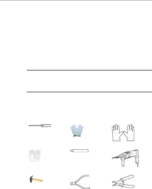
Tool Preparation
To install APs, prepare tools listed in Table 2-1.
Table 2-1 Tools
Phillips screwdriver |
Protective gloves |
ESD gloves |
|
|
|
Slip-proof glove |
Marker |
Hammer drill |
|
|
|
Claw hammer |
Diagonal pliers |
Wire stripper |
|
|
|
Issue 03 (2016-09-30) |
Huawei Proprietary and Confidential |
8 |
|
Copyright © Huawei Technologies Co., Ltd. |
|

AP6050DN & AP6150DN |
|
2 AP Installation |
|
Hardware Installation and Maintenance Guide |
|
||
|
|
|
|
|
RJ45 crimping tool |
Cable cutter |
Network cable tester |
|
|
|
|
|
Multimeter |
Ladder |
Safety helmet |
|
|
|
|
|
Safety belt |
Anti-skid shoes |
- |
|
|
|
|
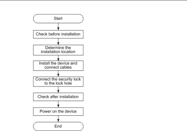
2.2 Installation Flowchart
The following figure shows the process for installing an AP.
Issue 03 (2016-09-30) |
Huawei Proprietary and Confidential |
9 |
|
Copyright © Huawei Technologies Co., Ltd. |
|
AP6050DN & AP6150DN |
2 AP Installation |
Hardware Installation and Maintenance Guide |
Figure 2-1 Installation flowchart
2.3 Unpacking the Equipment
Before unpacking the carton, ensure that the packing carton is intact and not damaged or soaked. Stop unpacking if the equipment is rusted or soggy. Then, investigate causes and contact the supplier.
After unpacking, check items in the carton against the packing list. If any item is missing, contact the supplier or agent.
Usually, the packing list contains the following items.
•AP device
•Antennas
•Sheet metal mounting bracket
•OT terminal
•Adjustable buckle
•Expansion screws
•Quick start guide
•Warranty card
•MAC address label
•SN label
Issue 03 (2016-09-30) |
Huawei Proprietary and Confidential |
10 |
|
Copyright © Huawei Technologies Co., Ltd. |
|
AP6050DN & AP6150DN |
2 AP Installation |
Hardware Installation and Maintenance Guide |
 NOTE
NOTE
•If a PoE adapter or a DC power adapter is required, you need to purchase it separately.
•Antennas are provided only in the carton of the AP6150DN.
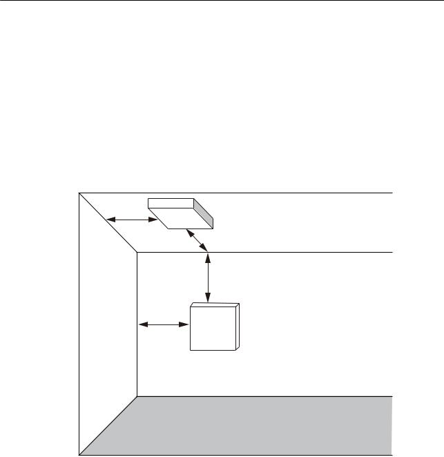
2.4Determining the Installation Position
Indoor APs are usually mounted on a wall or ceiling using sheet metal mounting brackets. The installation position is determined by the site survey. There must be at least 200 mm clearance between the cabling end of the AP and the wall. Figure 2-2 shows space requirements.
Figure 2-2 Mounting an AP
|
Celling |
|
≥200mm |
|
≥200mm |
|
≥200mm |
Wall |
≥200mm |
|
|
|
Floor |
When determining the AP installation position, comply with the following rules:
•Try to reduce the number of obstacles, such as walls, between the AP and user terminals.
•Place the AP far away from electronic devices that may produce radio interference, such as microwave ovens, other APs, antennas, and other radio communication devices. For details, see Table 2-2.
•Install the AP in a hidden position that does not affect daily lives and work of residents.
•Install the AP in a site that is free from leaking or dripping water, heavy dew, and humidity, and take protective measures to prevent water from flowing into the equipment along the cable.
•Do not install the AP in an environment with high temperature, dust, poisonous gases, flammable or explosive objects, electromagnetic interference (from a radar station, radio station, or substation), unstable voltage, violent shakes, or strong noise.
Issue 03 (2016-09-30) |
Huawei Proprietary and Confidential |
11 |
|
Copyright © Huawei Technologies Co., Ltd. |
|
AP6050DN & AP6150DN |
|
2 AP Installation |
|
Hardware Installation and Maintenance Guide |
|||
|
Table 2-2 General anti-interference requirements |
|
|
|
|
|
|
|
Scenario |
Deployment Distance Requirement |
|
|
|
|
|
|
Indoor |
• There should be at least a 7 m distance between antennas. |
|
|
installation |
• The antennas should be placed at least 2 m from the 4G antennas of |
|
|
|
||
|
|
the carrier. |
|
|
|
• The antennas should be placed far away from electronic devices that |
|
|
|
may produce interference, such as microwave ovens. |
|
|
|
|
|
 NOTE
NOTE
If antennas are embedded into APs, the deployment distance requirements on the antennas are those on APs.
2.5 Installing the AP
 NOTE
NOTE
•Remove the protective film on the surface before installation to prevent electrostatic discharge.
•The installation of the AP6150DN is used as an example.
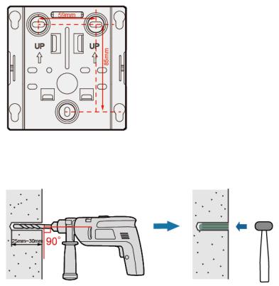
2.5.1Installing the Device on a Wall
Mounting APs on a wall requires sheet metal mounting brackets and expansion screws. The procedures are as follows:
1.Fix the mounting bracket to the wall, adjust the installation position, and use the marker to mark the drilling positions where expansion screws are installed.
2.Use a 6 mm drill bit to drill 25 mm to 30 mm deep holes in the drilling positions. Hammer the expansion tubes into the holes until the expansion tubes are completely embedded into the wall.
Issue 03 (2016-09-30) |
Huawei Proprietary and Confidential |
12 |
|
Copyright © Huawei Technologies Co., Ltd. |
|
AP6050DN & AP6150DN |
2 AP Installation |
Hardware Installation and Maintenance Guide |
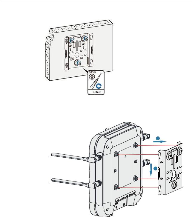
3.Fix the mounting bracket to the wall and use the Phillips screwdriver to fasten three expansion screws into the expansion tubes.
4.Connect the cables. For details, see 2.6 Cable Connection.
5.Align the mounting screws at the rear of the AP with the mounting holes on the sheet metal mounting bracket and then press the AP downwards to secure the AP on the bracket.
a
b 


2.5.2Installing the device on a Ceiling
1.Remove a ceiling tile, determine locations of mounting holes based on the distance between two installation holes on the mounting bracket, use a hammer drill to drill holes on the ceiling tile, and fix the mounting bracket to the ceiling tile.
The screws provided for ceiling-mounting of APs are 30 mm long and can be used to fix an AP on a ceiling not thicker than 15 mm. To install APs on thicker ceilings, you need to purchase longer screws.
Issue 03 (2016-09-30) |
Huawei Proprietary and Confidential |
13 |
|
Copyright © Huawei Technologies Co., Ltd. |
|

AP6050DN & AP6150DN |
2 AP Installation |
Hardware Installation and Maintenance Guide |
1. Ceiling tile |
2. Adjustable buckle |
3. M4x30 screw |
|
|
|
2.Connect the cables. For details, see 2.6 Cable Connection.
3.Hang the AP on the mounting holes by aligning the mounting screws at the rear of the AP with the mounting holes on the bracket and push the AP horizontally to secure the AP.
a
b
 NOTE
NOTE
Ensure that the AP is correctly installed on the mounting bracket and there must be 200 mm space above and around the AP for maintenance.
2.5.3 Installing the device on a T-rail
Issue 03 (2016-09-30) |
Huawei Proprietary and Confidential |
14 |
|
Copyright © Huawei Technologies Co., Ltd. |
|
AP6050DN & AP6150DN |
2 AP Installation |
Hardware Installation and Maintenance Guide |
1.Remove two ceiling tiles around the T-rail, use screws to fix the adjustable buckle to the mounting bracket, hook the adjustable buckle to the T-rail, and secure the screw on the adjustable buckle to fasten the mounting bracket and T-rail.
2.Connect the cables. For details, see 2.6 Cable Connection.
3.Hang the AP on the mounting holes by aligning the mounting screws at the rear of the AP with the mounting holes on the bracket and push the AP horizontally to secure the AP.
a
b
 NOTE
NOTE
•Before fixing the adjustable buckle with a screw, you need to adjust the buckle to a proper position based on the T-rail width.
•Ensure that the AP is correctly installed on the mounting bracket and there must be 200 mm space above and around the AP for maintenance.
Issue 03 (2016-09-30) |
Huawei Proprietary and Confidential |
15 |
|
Copyright © Huawei Technologies Co., Ltd. |
|
AP6050DN & AP6150DN |
2 AP Installation |
Hardware Installation and Maintenance Guide |
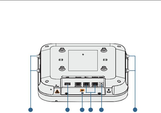
2.6 Cable Connection
Table 2-3 describes cable connections (the AP6150DN is used as an example).
Figure 2-3 Appearance of the AP6150DN
5 |
1 |
2 |
3 |
4 |
5 |
Table 2-3 Cable connections
No. |
Cable or Device |
Description |
|
|
|
1 |
USB flash drive |
Connects to a USB flash drive to extend the storage space |
|
|
of the AP, and provides a maximum of 2.5 W power. |
|
|
|
2 |
Ground cable |
Connects the AP to the ground. |
|
|
|
3 |
Network cable |
• CAT5e cables or higher must be used. |
|
|
• The service network cable and PoE input cable cannot |
|
|
be connected to the console port. Otherwise, the AP |
|
|
may be damaged when using PoE power supply. The |
|
|
network cable length cannot exceed 100 m. |
|
|
• If the AP needs to connect to the Ethernet, ensure that |
|
|
the Ethernet cable is working properly. If the Ethernet |
|
|
cable is not working properly, for example, RJ45 |
|
|
connectors are short-circuited, the AP may fail to be |
|
|
powered on or fail to work. Before connecting an |
|
|
Ethernet cable to the AP, use the cable test tool to |
|
|
check whether the cable is qualified. If the cable is |
|
|
unqualified, replace it. |
|
|
|
4 |
DC power adapter |
When the AP uses the DC power supply, use a power |
|
|
adapter for power supply; otherwise, the AP may be |
|
|
damaged. |
|
|
|
Issue 03 (2016-09-30) |
Huawei Proprietary and Confidential |
16 |
|
Copyright © Huawei Technologies Co., Ltd. |
|
AP6050DN & AP6150DN |
|
2 AP Installation |
|
Hardware Installation and Maintenance Guide |
|||
|
|
|
|
|
No. |
Cable or Device |
Description |
|
|
|
|
|
5 |
Antenna |
Connects to an external antenna for transmitting and |
|
|
|
receiving service signals. Only the AP6150DN provides |
|
|
|
antenna ports for connecting external antennas. |
|
|
|
|
 NOTE
NOTE
•The AP is powered by either the DC power supply or PoE power supply that backs up each other.
•By default, the USB port is disabled. You can enable it using the web platform or CLI. For details, see the configuration guide in the AC product documentation.
Pay attention to the following points when bundling the cables:
•Different types of cables must be separately routed with the minimum spacing of 30 mm and cannot be entangled or crossed. Cables should be parallel or separated using dedicated separators.
•Bundled cables are closely arranged, straight, tidy, and undamaged.
•Cable ties are bound neatly facing the same direction, and those at the same horizontal line must be in a straight line. Cable tie tails should be cut smoothly and evenly.
•Labels or nameplates must be attached to the cables after they are installed.
Connecting Antennas
Connect the antennas delivered in the installation accessory package of the AP to the RF ports on the AP, tighten the nuts (with a torque of 0.8 N•m), and adjust antenna angles as required.
Connecting the Ground Cable
Use ground screws and ground cables to ground the AP. The ground cables need to be prepared on site. The M4 OT terminal is used to connect to the AP and M6 OT terminals to the ground bar. The type of OT terminals can also be determined according to site surveys. Cut the cable into the required length according to site conditions.
Tighten the OT terminal for the AP with a torque of 3 N•m. The tightening torque for the ground bar varies according to the OT terminals used.
•M4: 1.4 N•m
•M6: 4.8 N•m
•M8: 12 N•m
Ground cable deployment requirements are as follows:
•The ground cables must be connected to a group of ground bars.
•The bend radius of the ground cables must be larger than or equal to five times the cable diameter.
•The ground cables must be buried underground or routed indoors and cannot be led into the equipment room aerially.
•Both ends of the external conductor of the coaxial cable and those of the shield layer of the shielded cable should have good electric contact with the metal shell of the equipment they connect to.
Issue 03 (2016-09-30) |
Huawei Proprietary and Confidential |
17 |
|
Copyright © Huawei Technologies Co., Ltd. |
|
AP6050DN & AP6150DN |
2 AP Installation |
Hardware Installation and Maintenance Guide |
•Ground cables must be separated from signal cables to reduce interference between them.
•Do not add any switch or fuse on the ground cable.
•Do not use another device for an electrical connection with the ground cable.
•All metal components in the shell must be securely connected to the ground terminal.
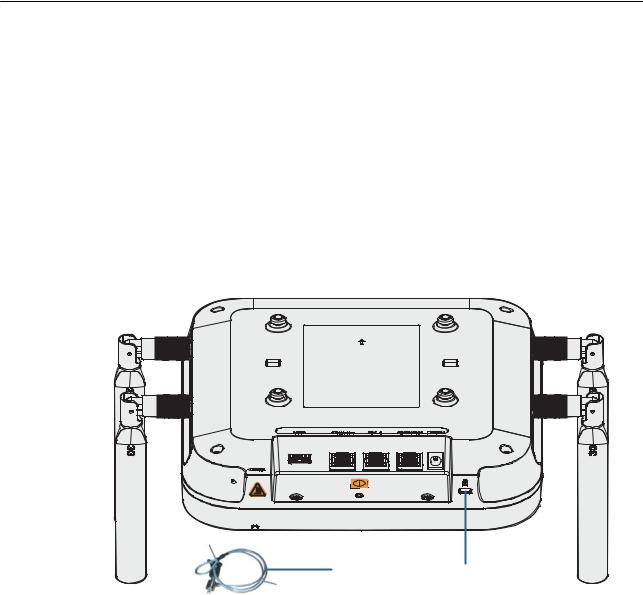
2.7Connecting the Security Lock
There is a security slot on the device. You can lock the device to an immovable object to prevent theft. The detailed procedures are as follows:
1.Fasten the cable of the security lock to an immovable object around.
2.Insert the security lock into the security slot and lock it.
Security lock |
Lock hole |
 NOTE
NOTE
You need to purchase the security lock separately.
2.8 Checking the Device After Installation
Table 2-4 shows the items to be checked after installation is complete. For more details, see
Installation Checklist in the appendix.
Table 2-4 Installation checklist
No. |
Check Item |
|
|
1 |
The device is installed by strictly following the design draft. The |
|
installation position meets space requirements, with maintenance space |
|
reserved. |
|
|
2 |
The device is securely installed. |
|
|
Issue 03 (2016-09-30) |
Huawei Proprietary and Confidential |
18 |
|
Copyright © Huawei Technologies Co., Ltd. |
|
AP6050DN & AP6150DN |
|
2 AP Installation |
|
Hardware Installation and Maintenance Guide |
|||
|
|
|
|
|
No. |
Check Item |
|
|
|
|
|
|
3 |
The power cables and PGND cables are intact and not spliced. |
|
|
|
|
|
|
4 |
Terminals of the power cables and PGND cables are welded or cramped |
|
|
|
firmly. |
|
|
|
|
|
|
5 |
All power cables or PGND cables are not short-circuited or reversely |
|
|
|
connected and must be intact with no damage. |
|
|
|
|
|
|
6 |
The power cables and ground cables are separated from other cables and |
|
|
|
bundled separately. |
|
|
|
|
|
|
7 |
The working ground, protection ground, and surge protection ground |
|
|
|
share the same group of ground bars. |
|
|
|
|
|
|
8 |
Connectors of signal cables are complete, intact, and tightly connected. |
|
|
|
The signal cables are not damaged or broken. |
|
|
|
|
|
|
9 |
Labels on cables, feeders, or jumpers are clear and correct. |
|
|
|
|
|
2.9 Powering on the AP
After the AP is powered on, observe indicator on the AP to determine the system running status. For details, see 1.2 Indicator Description.
 NOTE
NOTE
Do not frequently power on and off the device.
Issue 03 (2016-09-30) |
Huawei Proprietary and Confidential |
19 |
|
Copyright © Huawei Technologies Co., Ltd. |
|

AP6050DN & AP6150DN |
3 Logging In to the Device |
Hardware Installation and Maintenance Guide |
3Logging In to the Device
About This Chapter
3.1Logging In to the Device Using STelnet/Telnet
3.2Logging In to the Device Through the Web System (Applicable to the Fat AP Only)
3.3Logging In to the Device Through the Console Port
Issue 03 (2016-09-30) |
Huawei Proprietary and Confidential |
20 |
|
Copyright © Huawei Technologies Co., Ltd. |
|

AP6050DN & AP6150DN |
3 Logging In to the Device |
Hardware Installation and Maintenance Guide |
3.1 Logging In to the Device Using STelnet/Telnet
You can log in to the device using STelnet V2 or Telnet to configure, manage, and maintain the device in the CLI.
 NOTE
NOTE
•By default, only the STelnet V2 service is enabled on the device.
•Telnet has security vulnerabilities. You are not advised to enable the Telnet service.
Before logging in to the device, complete the following tasks:
•Power on the device.
•Prepare network cables used to connect device interfaces.
The following table lists the default configuration of the device. You are advised to change the default user name and password on your first login.
Table 3-1 Default configuration of the device
Parameter |
Default Setting |
|
|
User name |
admin |
|
|
Password |
admin@huawei.com |
|
|
IP address |
169.254.1.1 |
|
|
Subnet mask |
255.255.0.0 |
|
|
 NOTE
NOTE
If a Fit AP is already online on the AC, you can remotely log in to the AC on a local terminal and run the display ap all command to check the IP address of the device.
The following example uses the default parameters and is used for reference only.
Step 1 Use network cables and a LAN switch to connect the PC to the network interface of the device.
Step 2 Assign the PC with an IP address on the same network segment as the default IP address of the device so that the PC and device are reachable to each other.
If the device uses the default settings, the IP address of the PC must be in the network segment 169.254.0.0/16 but cannot be 169.254.1.1. 169.254.1.100 is recommended.
Step 3 Start the CLI on the PC and access the IP address 169.254.1.1 of the device using STelnet V2.
Step 4 Enter the user name and password as prompted to log in to the user interface.
----End
Issue 03 (2016-09-30) |
Huawei Proprietary and Confidential |
21 |
|
Copyright © Huawei Technologies Co., Ltd. |
|

AP6050DN & AP6150DN |
3 Logging In to the Device |
Hardware Installation and Maintenance Guide |
3.2 Logging In to the Device Through the Web System (Applicable to the Fat AP Only)
A Fat AP has a built-in web system. You can use a web browser to log in to the device to configure, manage, and maintain the device on a graphic user interface (GUI).
Before logging in to the device, complete the following tasks:
•Power on the device.
•Prepare network cables used to connect device interfaces.
The following table lists the default configuration of the device. You are advised to change the default user name and password on your first login.
Table 3-2 Default configuration of the device
Parameter |
Default Setting |
|
|
User name |
admin |
|
|
Password |
admin@huawei.com |
|
|
IP address |
169.254.1.1 |
|
|
Subnet mask |
255.255.0.0 |
|
|
Step 1 Use network cables and a LAN switch to connect the PC to the network interface of the device.
Step 2 Assign the PC with an IP address on the same network segment as the default IP address of the device so that the PC and device are reachable to each other.
If the device uses the default settings, the IP address of the PC must be in the network segment 169.254.0.0/16 but cannot be 169.254.1.1. 169.254.1.100 is recommended.
Step 3 Open the browser on the PC, enter http://IP address in the address box, and press Enter to log in. Select a language for the web system, enter the default user name and password, and click Login to enter the web system home page.
----End
3.3 Logging In to the Device Through the Console Port
Before logging in to the device, complete the following tasks:
•Power on the device.
•Prepare a console cable.
•Prepare terminal simulation software.
Issue 03 (2016-09-30) |
Huawei Proprietary and Confidential |
22 |
|
Copyright © Huawei Technologies Co., Ltd. |
|

AP6050DN & AP6150DN |
3 Logging In to the Device |
Hardware Installation and Maintenance Guide |
 NOTE
NOTE
If your PC's operating system provides terminal simulation software (like HyperTerminal in Windows 2000/ XP), you do not need to install additional terminal simulation software. If the PC runs on an operating system without terminal simulation software (like Windows 7), install third-party terminal simulation software on the PC by referring to the user manual or online help.
Step 1 Use a console cable to connect the PC to the console port of the device.
Step 2 Start terminal emulation software on the PC, create a connection, and set communication parameters as follows:
•Bits per second: 9600
•Data bits: 8
•Parity: None
•Stop bits: 1
•Flow control (F): None
Step 3 Press Enter and enter the authentication information as prompted to log in to the user view. (The following information is only for reference.)
For a Fit AP, enter the default user name admin and password admin@huawei.com.
You are advised to change the default user name and password on your first login.
Login authentication
Username:
Password:
Info: You are advised to change the password to ensure security.
For a Fat AP, set a passowrd of console, and use the password to log in.
Please configure the login password:
Info: A plain text password is a string of 8 to 16 case-sensitive characters and must be a combination of at least two of the follow
ing: uppercase letters A to Z, lowercase letters a to z, digits, and special characters. A cipher text password contains 56 or 68 ch
aracters.
Enter password: Confirm password:
----End
Issue 03 (2016-09-30) |
Huawei Proprietary and Confidential |
23 |
|
Copyright © Huawei Technologies Co., Ltd. |
|

AP6050DN & AP6150DN |
4 Hardware Failures |
Hardware Installation and Maintenance Guide |
4Hardware Failures
About This Chapter
This section describes common methods for troubleshooting typical hardware faults.
4.1 A Device Fails to Be Powered On
Issue 03 (2016-09-30) |
Huawei Proprietary and Confidential |
24 |
|
Copyright © Huawei Technologies Co., Ltd. |
|
Loading...