


 Loading...
AP3x10xN&5x10xN&5x30xN&6x10xN&7x10xN
Hardware Installation and
Maintenance Guide
Issue 12
Date 2015-08-05
HUAWEI TECHNOLOGIES CO., LTD.

Copyright © Huawei Technologies Co., Ltd. 2015. All rights reserved.
No part of this document may be reproduced or transmitted in any form or by any means without prior written consent of Huawei Technologies Co., Ltd.
Trademarks and Permissions


 and other Huawei trademarks are trademarks of Huawei Technologies Co., Ltd.
All other trademarks and trade names mentioned in this document are the property of their respective holders.
Notice
The purchased products, services and features are stipulated by the contract made between Huawei and the customer. All or part of the products, services and features described in this document may not be within the purchase scope or the usage scope. Unless otherwise specified in the contract, all statements, information, and recommendations in this document are provided "AS IS" without warranties, guarantees or representations of any kind, either express or implied.
The information in this document is subject to change without notice. Every effort has been made in the preparation of this document to ensure accuracy of the contents, but all statements, information, and recommendations in this document do not constitute a warranty of any kind, express or implied.
Huawei Technologies Co., Ltd.
Address: |
Huawei Industrial Base |
|
Bantian, Longgang |
|
Shenzhen 518129 |
|
People's Republic of China |
Website: |
http://e.huawei.com |
Issue 12 (2015-08-05) |
Huawei Proprietary and Confidential |
i |
|
Copyright © Huawei Technologies Co., Ltd. |
|
AP3x10xN&5x10xN&5x30xN&6x10xN&7x10xN |
|
Hardware Installation and Maintenance Guide |
About This Document |
About This Document
Intended Audience
This document describes hardware features of AP3x10xN, 5x10xN, 5x30xN, 6x10xN and 7x10xN, and provides basic installation methods.
This document is intended for:
•Network planning engineers
•Hardware installation engineers
•Commissioning engineers
•Onsite maintenance engineers
•System maintenance engineers
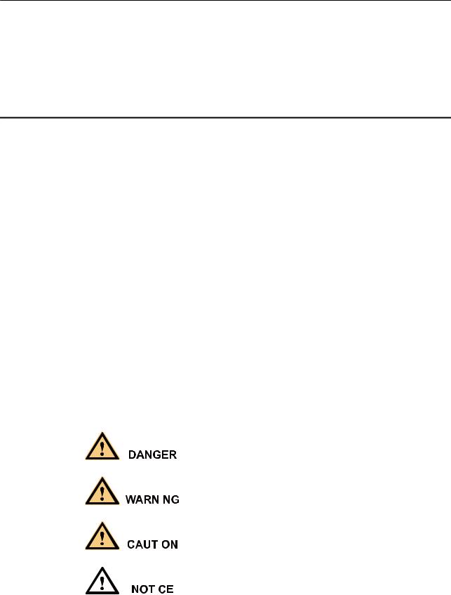
Symbol Conventions
The symbols that may be found in this document are defined as follows.
Symbol |
Description |
||
|
|
|
|
|
|
|
Indicates an imminently hazardous situation |
|
|
|
which, if not avoided, will result in death or |
|
|
|
serious injury. |
|
|
|
|
|
|
|
Indicates a potentially hazardous situation |
|
|
|
which, if not avoided, could result in death or |
|
|
|
|
|
|
|
serious injury. |
|
|
|
|
|
|
|
|
|
|
|
Indicates a potentially hazardous situation |
|
|
|
which, if not avoided, may result in minor or |
|
|
|
|
|
|
|
moderate injury. |
|
|
|
|
|
|
|
|
|
|
|
Indicates a potentially hazardous situation |
|
|
|
which, if not avoided, could result in |
|
|
|
|
|
|
|
equipment damage, data loss, performance |
|
|
|
|
|
|
|
deterioration, or unanticipated results. |
|
|
|
NOTICE is used to address practices not |
|
|
|
related to personal injury. |
|
|
|
|
Issue 12 (2015-08-05) |
Huawei Proprietary and Confidential |
ii |
|
Copyright © Huawei Technologies Co., Ltd. |
|

AP3x10xN&5x10xN&5x30xN&6x10xN&7x10xN |
|
|
Hardware Installation and Maintenance Guide |
About This Document |
|
|
|
|
|
Symbol |
Description |
|
|
|
|
NOTE |
Calls attention to important information, best |
|
|
practices and tips. |
|
|
NOTE is used to address information not |
|
|
related to personal injury, equipment damage, |
|
|
and environment deterioration. |
|
|
|
Change History
Changes between document issues are cumulative. The latest document issue contains all changes made in previous issues.
Issue 12 (2015-08-05)
This version has the following updates:
Updated the packing list.
Issue 11 (2015-05-18)
This version has the following updates:
The following information is modified:
•Added the command to check AP running status in V200R006C00.
•Added descriptions about PoE fault troubleshooting.
Issue 10 (2014-12-05)
This version has the following updates:
The following information is added:
•1.4 Ordering Information.
Issue 09 (2014-07-30)
This version has the following updates:
The following information is modified:
•Optimized the installation steps.
The following information is added:
•Logging in to the AP using STelnet.
Issue 08 (2013-04-10)
This version has the following updates:
The following information is added:
Issue 12 (2015-08-05) |
Huawei Proprietary and Confidential |
iii |
|
Copyright © Huawei Technologies Co., Ltd. |
|

AP3x10xN&5x10xN&5x30xN&6x10xN&7x10xN |
|
Hardware Installation and Maintenance Guide |
About This Document |
•AP5030DN and AP5130DN installation guide
•Note: The network cable cannot exceed 100 meters.
Issue 07 (2014-01-15)
This version has the following updates:
Optimized the manual.
Issue 06 (2013-09-30)
This version has the following updates:
The following information is modified:
•AP's default IP address and login password
Issue 05 (2013-06-29)
This version has the following updates:
The following information is modified:
•Figure for converting SMA connectors to type—N connectors
Issue 04 (2013-04-30)
This version has the following updates:
The following information is modified:
•Figure of the sheet metal mounting brackets delivered with APs
Issue 03 (2013-01-30)
This version has the following updates:
The following information is added:
•Descriptions about power adapters delivered with APs
•Section: Removing an AP
Issue 02 (2012-12-31)
This version has the following updates:
The following information is added:
•Power adapter cable connection figure
Issue 01 (2012-10-31)
Initial commercial release
Issue 12 (2015-08-05) |
Huawei Proprietary and Confidential |
iv |
|
Copyright © Huawei Technologies Co., Ltd. |
|

AP3x10xN&5x10xN&5x30xN&6x10xN&7x10xN |
|
Hardware Installation and Maintenance Guide |
Contents |
Contents
About This Document..................................................................................................................... |
|
ii |
|
1 Indoor AP Overview..................................................................................................................... |
|
1 |
|
1.1 |
Device Structure............................................................................................................................................................. |
|
1 |
1.2 |
Indicator Description...................................................................................................................................................... |
|
4 |
1.3 |
Basic Specifications........................................................................................................................................................ |
|
7 |
1.4 |
Ordering Information.................................................................................................................................................... |
|
10 |
2 AP Installation............................................................................................................................. |
|
14 |
|
2.1 |
Preparing for Installation.............................................................................................................................................. |
|
14 |
2.2 |
Installation Flowchart................................................................................................................................................... |
|
15 |
2.3 |
Unpacking the Equipment............................................................................................................................................ |
|
17 |
2.4 |
Determining the Installation Position........................................................................................................................... |
|
18 |
2.5 |
Installing the AP........................................................................................................................................................... |
|
19 |
2.5.1 Wall Mounting........................................................................................................................................................... |
|
20 |
|
2.5.2 Ceiling Mounting....................................................................................................................................................... |
|
22 |
|
2.5.3 T-rail Mounting......................................................................................................................................................... |
|
23 |
|
2.5.4 Removing an AP........................................................................................................................................................ |
|
24 |
|
2.6 |
Connecting Cables........................................................................................................................................................ |
|
25 |
2.7 |
Installing the Security Lock.......................................................................................................................................... |
|
29 |
2.8 |
Checking the AP After Installation.............................................................................................................................. |
|
29 |
2.9 |
Powering on the AP...................................................................................................................................................... |
|
30 |
3 Logging In to the AP................................................................................................................... |
|
31 |
|
3.1 |
Logging In to the AP Through the Console Port.......................................................................................................... |
31 |
|
3.2 |
Logging In to the AP Using STelnet............................................................................................................................ |
|
31 |
3.3 |
Logging In to the AP Using Telnet.............................................................................................................................. |
|
33 |
3.4 |
Logging In to the AP Using a Web Client.................................................................................................................... |
34 |
|
4 Hardware Failures....................................................................................................................... |
|
35 |
|
4.1 |
A Device Fails to Be Powered On................................................................................................................................ |
|
35 |
4.2 |
An Optical Interface Cannot Turn Up.......................................................................................................................... |
|
36 |
5 Appendix....................................................................................................................................... |
|
38 |
|
5.1 |
On-site Cable Assembly and Installation..................................................................................................................... |
38 |
|
Issue 12 (2015-08-05) |
Huawei Proprietary and Confidential |
v |
|
|
Copyright © Huawei Technologies Co., Ltd. |
|
|

AP3x10xN&5x10xN&5x30xN&6x10xN&7x10xN |
|
Hardware Installation and Maintenance Guide |
Contents |
5.1.1 Cable Assembly Precautions..................................................................................................................................... |
38 |
5.1.2 Assembling Power Cables......................................................................................................................................... |
39 |
5.1.3 Assembling Ethernet Cables...................................................................................................................................... |
48 |
5.1.4 Installing Cable Accessories...................................................................................................................................... |
62 |
5.1.5 Replacing the Mold of the Crimping Tool................................................................................................................ |
77 |
5.2 Environmental Requirements for Device Operation.................................................................................................... |
81 |
5.2.1 Environmental Requirements for an Equipment Room............................................................................................ |
81 |
5.2.2 Requirements for Power Supply................................................................................................................................ |
88 |
5.3 Equipment Grounding Specifications........................................................................................................................... |
91 |
5.3.1 General Grounding Specifications............................................................................................................................. |
91 |
5.3.2 Grounding Specifications for an Equipment Room.................................................................................................. |
91 |
5.3.3 Grounding Specifications for Devices....................................................................................................................... |
91 |
5.3.4 Grounding Specifications for Communications Power Supply................................................................................. |
92 |
5.3.5 Grounding Specifications for Signal Cables............................................................................................................. |
93 |
5.3.6 Specifications for Laying Out Grounding Cables..................................................................................................... |
93 |
5.4 Engineering Labels for Cables..................................................................................................................................... |
94 |
5.4.1 Introduction to Labels................................................................................................................................................ |
94 |
5.4.2 Engineering Labels for Optical Fibers..................................................................................................................... |
102 |
5.4.3 Engineering Labels for Network Cables................................................................................................................. |
105 |
5.4.4 Engineering Labels for User Cables........................................................................................................................ |
106 |
5.4.5 Engineering Labels for Power Cables..................................................................................................................... |
107 |
5.5 Guide to Using Optical Modules................................................................................................................................ |
110 |
5.6 Fault Tag..................................................................................................................................................................... |
113 |
Issue 12 (2015-08-05) |
Huawei Proprietary and Confidential |
vi |
|
Copyright © Huawei Technologies Co., Ltd. |
|
AP3x10xN&5x10xN&5x30xN&6x10xN&7x10xN |
|
Hardware Installation and Maintenance Guide |
1 Indoor AP Overview |
1Indoor AP Overview
1.1 Device Structure
Figures in Table 1-1 show the appearance of indoor APs.
 CAUTION
There is a scald warning label attached on some devices, warning you not to touch the device after the device has been operating for a long time.
Table 1-1 Appearance of indoor APs
Product Model |
Appearance |
|
|
|
|
AP3010DN-AGN |
|
|
|
|
|
AP5010DN-AGN |
|
|
|
|
|
AP5010SN-GN |
|
|
|
|
|
AP6010DN-AGN |
|
|
|
|
|
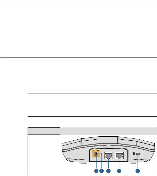
AP6010SN-GN |
DC 12V Default ETH/PoE |
Console |
|
||
|
|
||||
|
1 |
2 |
3 |
6 |
7 |
Issue 12 (2015-08-05) |
Huawei Proprietary and Confidential |
1 |
|
Copyright © Huawei Technologies Co., Ltd. |
|

AP3x10xN&5x10xN&5x30xN&6x10xN&7x10xN
Hardware Installation and Maintenance Guide |
1 Indoor AP Overview |
|
|
|
|
|
Product Model |
Appearance |
|
|
|
AP5030DN
Console |
GE1 |
GE0/PoE DC 12V |
2 |
6 |
4 |
5 |
1 |
7 |
AP5130DN |
|
|
|
|
10 |
Console |
GE1 |
GE0/PoE DC 12V |
2 |
6 |
4 |
5 |
1 |
7 |
AP6310SN-GN
2.4G |
Console |
ETH/PoE |
Default |
DC 12V |
|
8 |
6 |
3 |
2 |
1 |
11 |
Issue 12 (2015-08-05) |
Huawei Proprietary and Confidential |
2 |
|
Copyright © Huawei Technologies Co., Ltd. |
|
AP3x10xN&5x10xN&5x30xN&6x10xN&7x10xN |
|
Hardware Installation and Maintenance Guide |
1 Indoor AP Overview |
Product Model |
Appearance |
|
|
|
|
|
|
|
AP7110DN-AGN |
|
|
|
|
|
|
|
|
|
|
|
Console |
ETH/PoE |
Default DC 12V |
|
|
|
|
9 |
11 |
6 |
3 |
2 |
1 |
7 |
8 |
AP7110SN-GN
Console |
ETH/PoE |
Default DC 12V |
11 6 3 2 1 7 8
Table 1-2 describes interfaces on indoor APs.
Table 1-2 Interfaces on indoor APs
No. |
Name |
Description |
|
|
|
1 |
DC 12 V |
DC power socket: connects a 12 V power |
|
|
adapter to the AP. |
|
|
|
2 |
Default |
Reset button: restores factory settings if you |
|
|
hold down the button more than 3s. |
|
|
|
3 |
ETH/PoE |
10/100/1000M bit/s interface: connects to the |
|
|
wired Ethernet. The interface can connect to |
|
|
a PoE power supply to provide power for the |
|
|
AP. |
|
|
|
4 |
GE1 |
10/100/1000M bit/s interface: connects to the |
|
|
wired Ethernet. |
|
|
|
5 |
GE0/PoE |
10/100/1000M bit/s interface: connects to the |
|
|
wired Ethernet. The interface can connect to |
|
|
a PoE power supply to provide power for the |
|
|
AP. |
|
|
|
6 |
Console |
Console interface: connects to a maintenance |
|
|
terminal for AP configuration and |
|
|
management. |
|
|
|
7 |
Security slot |
Connects to a security lock. |
|
|
|
8 |
2.4 GHz antenna port |
Connects a 2.4 GHz antenna to the AP. |
|
|
|
Issue 12 (2015-08-05) |
Huawei Proprietary and Confidential |
3 |
|
Copyright © Huawei Technologies Co., Ltd. |
|
AP3x10xN&5x10xN&5x30xN&6x10xN&7x10xN |
|
|||
Hardware Installation and Maintenance Guide |
|
1 Indoor AP Overview |
||
|
|
|
|
|
|
No. |
|
Name |
Description |
|
|
|
|
|
|
9 |
|
5 GHz antenna port |
Connects a 5 GHz antenna to the AP. |
|
|
|
|
|
|
10 |
|
Dual-band antenna |
Connects a dual-band antenna to the AP. |
|
|
|
port |
|
|
|
|
|
|
|
11 |
|
Device ground screw |
Connects a ground cable to the AP. |
|
|
|
|
|
1.2 Indicator Description
Indoor AP series products provide a single indicator or multiple indicators.
•The AP3010DN-AGN, AP5010DN-AGN, AP5010SN-GN, AP5030DN, AP5130DN, AP6010DN-AGN, and AP6010SN-GN provide only a single indicator.
•The AP6310SN-GN, AP7110DN-AGN, and AP7110SN-GN provide multiple indicators: SYS indicator, Link indicator, and Wireless indicator.
The following table describes indicators on indoor APs.
 NOTE
NOTE
•Indicator colors may vary slightly at different temperature.
•After a Fit AP is powered on, you can run the led off command on the AC to turn off all AP indicators. To restore the indicators to normal working status, run the led on command. Indicators on a Fat AP cannot be turned off using the led off command.
Single indicator and SYS indicator
Table 1-3 Descriptions about the single indicator and SYS indicator
Type |
Color |
Status |
Description |
|
|
|
|
Default |
Green |
Steady on |
The AP is just powered on and the software is not |
status after |
|
|
started yet. |
power-on |
|
|
|
|
|
|
|
Software |
Green |
Steady on |
After the system is reset and starts uploading the |
startup |
|
after |
software, the indicator blinks green once. Until the |
status |
|
blinking |
software is uploaded and started, the indicator |
|
|
once |
remains steady green. |
|
|
|
|
Running |
Green |
Blinking |
• The system is running properly, the Ethernet |
status |
|
once every |
connection is normal, and STAs are associated |
|
|
2s (0.5 Hz) |
with the AP. |
|
|
|
• The system enters the Uboot CLI. |
|
|
|
|
|
|
Blinking |
The system is running properly, the Ethernet |
|
|
once every |
connection is normal, and no STA is associated with |
|
|
5s (0.2 Hz) |
the AP. The system is in low power consumption |
|
|
|
state. |
|
|
|
|
Issue 12 (2015-08-05) |
Huawei Proprietary and Confidential |
4 |
|
Copyright © Huawei Technologies Co., Ltd. |
|
AP3x10xN&5x10xN&5x30xN&6x10xN&7x10xN |
|
|||
Hardware Installation and Maintenance Guide |
|
1 Indoor AP Overview |
||
|
|
|
|
|
|
Type |
Color |
Status |
Description |
|
|
|
|
|
|
Alarm |
Green |
Blinking |
• The software is being upgraded. |
|
|
|
once every |
• After the software is uploaded and started, the AP |
|
|
|
0.25s (4 |
working in Fit AP mode requests to go online on |
|
|
|
Hz) |
|
|
|
|
the AC and maintains this state until it goes |
|
|
|
|
|
|
|
|
|
|
online successfully on the AC (before the |
|
|
|
|
CAPWAP link is established). |
|
|
|
|
• The AP working in Fit AP mode fails to go online |
|
|
|
|
on the AC (the CAPWAP link disconnects). |
|
|
|
|
|
|
Fault |
Red |
Steady on |
A fault that affects services has occurred, such as a |
|
|
|
|
DRAM detection failure or system software loading |
|
|
|
|
failure. The fault cannot be automatically rectified |
|
|
|
|
and must be rectified manually. |
|
|
|
|
|
Link indicator
Table 1-4 Descriptions about the Link indicator
Type |
Color |
Status |
Description |
|
|
|
|
LINK |
Green |
Steady on |
The system is running properly, the Ethernet |
|
|
|
connection is normal, and no data is being |
|
|
|
transmitted. |
|
|
|
|
ACT |
Green |
Blinking |
The system is running properly, the Ethernet |
|
|
|
connection is normal, and the AP is transmitting |
|
|
|
data. The indicator blinks more quickly when more |
|
|
|
data is being transmitted. |
|
|
|
|
Wireless indicator
Table 1-5 Descriptions about the Wireless indicator in traffic volume mode
Color |
Status |
Description |
|
|
|
Yellow/green |
Off |
Radios are disabled, and no STA is connected |
|
|
to the AP. |
|
|
|
Yellow/green |
Steady on |
The AP has STAs connected to the 2.4 GHz |
|
|
radio or 5 GHz radio, but no data is being |
|
|
transmitted. |
|
|
|
Issue 12 (2015-08-05) |
Huawei Proprietary and Confidential |
5 |
|
Copyright © Huawei Technologies Co., Ltd. |
|
AP3x10xN&5x10xN&5x30xN&6x10xN&7x10xN |
|
|||
Hardware Installation and Maintenance Guide |
|
1 Indoor AP Overview |
||
|
|
|
|
|
|
Color |
|
Status |
Description |
|
|
|
|
|
|
Green |
|
Blinking |
The AP has STAs connected to the 2.4 GHz |
|
|
|
|
radio and is transmitting data. The indicator |
|
|
|
|
blinks more quickly when more data is being |
|
|
|
|
transmitted. |
|
|
|
|
|
|
Yellow |
|
Blinking |
The AP has STAs connected to the 5 GHz |
|
|
|
|
radio and is transmitting data. The indicator |
|
|
|
|
blinks more quickly when more data is being |
|
|
|
|
transmitted. |
|
|
|
|
|
|
Yellow/green |
|
Blinking |
The AP has STAs connected to both the 2.4 |
|
|
|
alternatively |
GHz radio and 5 GHz radio. The indicator |
|
|
|
|
blinks more quickly when more data is being |
|
|
|
|
transmitted. |
|
|
|
|
|
|
Table 1-6 Descriptions about the Wireless indicator in signal strength mode |
|||
|
|
|
|
|
|
Color |
|
Status |
Description |
|
|
|
|
|
|
Yellow/green |
|
Off |
The AP is not transmitting or receiving data |
|
|
|
|
or the signal strength is extremely low. |
|
|
|
|
|
|
|
|
Blinking once every |
The AP is transmitting or receiving data |
|
|
|
2s (0.5 Hz) |
normally, and the signal strength is low. |
|
|
|
|
|
|
|
|
Blinking green once |
The AP is transmitting or receiving data |
|
|
|
every 0.25 seconds (4 |
normally, and the signal strength is medium. |
|
|
|
Hz) |
|
|
|
|
|
|
|
|
|
Steady on |
The AP is transmitting or receiving data |
|
|
|
|
normally, and the signal strength is high. |
|
|
|
|
|
Issue 12 (2015-08-05) |
Huawei Proprietary and Confidential |
6 |
|
Copyright © Huawei Technologies Co., Ltd. |
|

AP3x10xN&5x10xN&5x30xN&6x10xN&7x10xN |
|
Hardware Installation and Maintenance Guide |
1 Indoor AP Overview |
 NOTE
NOTE
When the WDS/Mesh function is enabled on an AP, the blinking frequency of its Wireless indicator indicates the receive signal strength on the WDS/Mesh connection by default. After you connect an AP to a WDS/Mesh network, you can run the wifi-light { signal-strength | traffic } command on the AC to make the Wireless indicator blinking frequency indicate receive signal strength or service traffic rate.
•wifi-light signal-strength:
• If the Mesh function is enabled on the AP, the blinking frequency of the Wireless indicator reflects the weakest signal strength of all neighboring APs.
• If WDS is enabled on an AP, the blinking frequency of the Wireless indicator reflects the strength of signals received from a WDS AP.
•If the AP works in leaf mode, the blinking frequency of the Wireless indicator reflects the strength of signals received from a middle AP.
•If the AP works in middle mode, the blinking frequency of the Wireless indicator reflects the strength of signals received from a root AP.
•If the AP works in root mode, the blinking frequency of the Wireless indicator reflects the weakest signal strength of middle APs.
• wifi-light traffic: allows the Wireless indicator to reflect the service traffic volume on the radio. When an AP functions as a Fat AP, the Wireless indicator of the AP can not reflect the signal strength.
The AP6310SN-GN does not support WDS/Mesh functions; therefore, the Wireless indicator of the AP6310SN-GN does not indicate the signal strength.
1.3 Basic Specifications
Table 1-7 Basic specifications of the AP3010DN-AGN, AP5010SN-GN, AP5010DN-AGN, AP6010DN-AGN, and AP6010SN-GN
Item |
|
Description |
|
|
|
Technical |
Dimensions (H x W x |
50 mm x 180 mm x 180 mm |
specifications |
D) |
|
|
|
|
|
Weight |
0.4 kg |
|
|
|
|
System memory |
• 256 MB DDR2 |
|
|
• 32 MB flash memory |
|
|
|
Power specifications |
Power input |
• DC 12 V ± 10% |
|
|
• PoE power supply: in compliance with |
|
|
IEEE 802.3af/at |
|
|
NOTE |
|
|
The AP6010DN-AGN and AP6010SN-GN cannot |
|
|
use the PoE power supply and DC power supply |
|
|
simultaneously. |
|
|
|
Issue 12 (2015-08-05) |
Huawei Proprietary and Confidential |
7 |
|
Copyright © Huawei Technologies Co., Ltd. |
|
AP3x10xN&5x10xN&5x30xN&6x10xN&7x10xN |
|
|||
Hardware Installation and Maintenance Guide |
|
1 Indoor AP Overview |
||
|
|
|
|
|
|
Item |
|
Description |
|
|
|
|
|
|
|
|
|
Maximum power |
• AP3010DN-AGN: 9.5 W |
|
|
|
consumption |
• AP5010DN-AGN: 9.5 W |
|
|
|
|
|
|
|
|
|
• AP5010SN-GN: 6.0 W |
|
|
|
|
• AP6010DN-AGN: 10.2 W |
|
|
|
|
• AP6010SN-GN: 6.5 W |
|
|
|
|
NOTE |
|
|
|
|
The actual maximum power consumption depends |
|
|
|
|
on local laws and regulations. |
|
|
|
|
|
|
Environment |
|
Operating |
-60 m to +1800 m: -10°C to +50°C |
|
specifications |
|
temperature and |
1800 m to 5000 m: Temperature decreases by |
|
|
|
altitude |
|
|
|
|
1°C every time the altitude increases 300 m. |
|
|
|
|
|
|
|
|
|
|
|
|
|
|
Storage temperature |
-40°C to +70°C |
|
|
|
|
|
|
|
|
Operating humidity |
5% to 95% (non-condensing) |
|
|
|
|
|
|
|
|
IP grade |
IP31 |
|
|
|
|
|
|
|
|
Atmospheric |
70 kPa to 106 kPa |
|
|
|
pressure |
|
|
|
|
|
|
|
Table 1-8 Basic specifications of the AP5030DN and AP5130DN |
|||
|
|
|
|
|
|
Item |
|
Description |
|
|
|
|
|
|
|
Technical |
|
Dimensions (H x W x |
53 mm x 220 mm x 220 mm |
|
specifications |
|
D) |
|
|
|
|
|
|
|
|
|
Weight |
1.0 kg |
|
|
|
|
|
|
|
|
System memory |
• 256 MB DDR2 |
|
|
|
|
• 32 MB flash memory |
|
|
|
|
|
|
Power specifications |
|
Power input |
• DC 12 V ± 10% |
|
|
|
|
• PoE power: -48 V DC (in compliance with |
|
|
|
|
IEEE 802.3af/at) |
|
|
|
|
|
|
|
|
Maximum power |
12.95 W |
|
|
|
consumption |
NOTE |
|
|
|
|
The actual maximum power consumption depends |
|
|
|
|
on local laws and regulations. |
|
|
|
|
|
|
Environment |
|
Operating |
-60 m to +1800 m: -10°C to +50°C |
|
specifications |
|
temperature and |
1800 m to 5000 m: Temperature decreases by |
|
|
|
altitude |
|
|
|
|
1°C every time the altitude increases 300 m. |
|
|
|
|
|
|
|
|
|
|
|
|
|
|
Storage temperature |
-40°C to +70°C |
|
|
|
|
|
Issue 12 (2015-08-05) |
Huawei Proprietary and Confidential |
8 |
|
Copyright © Huawei Technologies Co., Ltd. |
|
AP3x10xN&5x10xN&5x30xN&6x10xN&7x10xN |
|
|||
Hardware Installation and Maintenance Guide |
|
1 Indoor AP Overview |
||
|
|
|
|
|
|
Item |
|
Description |
|
|
|
|
|
|
|
|
|
Operating humidity |
5% to 95% (non-condensing) |
|
|
|
|
|
|
|
|
IP grade |
IP41 |
|
|
|
|
|
|
|
|
Atmospheric |
70 kPa to 106 kPa |
|
|
|
pressure |
|
|
|
|
|
|
|
Table 1-9 Basic specifications of the AP6310SN-GN |
|||
|
|
|
|
|
|
Item |
|
Description |
|
|
|
|
|
|
|
Technical |
|
Dimensions (H x W x |
35 mm x 150 mm x 130 mm |
|
specifications |
|
D) |
|
|
|
|
|
|
|
|
|
Weight |
0.6 kg |
|
|
|
|
|
|
|
|
System memory |
• 128 MB DDR2 |
|
|
|
|
• 32 MB flash memory |
|
|
|
|
|
|
Power specifications |
|
Power input |
• DC 12 V ± 10% |
|
|
|
|
• PoE power supply: -48 V DC (in |
|
|
|
|
compliance with IEEE 802.3af/at) |
|
|
|
|
NOTE |
|
|
|
|
The AP6310SN-GN cannot use the PoE power |
|
|
|
|
supply and DC power supply simultaneously. |
|
|
|
|
|
|
|
|
Maximum power |
8.3 W |
|
|
|
consumption |
NOTE |
|
|
|
|
The actual maximum power consumption depends |
|
|
|
|
on local laws and regulations. |
|
|
|
|
|
|
Environment |
|
Operating |
-60 m to +1800 m: -10°C to +50°C |
|
specifications |
|
temperature and |
1800 m to 5000 m: Temperature decreases by |
|
|
|
altitude |
|
|
|
|
1°C every time the altitude increases 300 m. |
|
|
|
|
|
|
|
|
|
|
|
|
|
|
Storage temperature |
-40°C to +70°C |
|
|
|
|
|
|
|
|
Operating humidity |
5% to 95% (non-condensing) |
|
|
|
|
|
|
|
|
IP grade |
IP31 |
|
|
|
|
|
|
|
|
Atmospheric |
70 kPa to 106 kPa |
|
|
|
pressure |
|
|
|
|
|
|
Issue 12 (2015-08-05) |
Huawei Proprietary and Confidential |
9 |
|
Copyright © Huawei Technologies Co., Ltd. |
|
AP3x10xN&5x10xN&5x30xN&6x10xN&7x10xN |
|
|||
Hardware Installation and Maintenance Guide |
|
1 Indoor AP Overview |
||
|
Table 1-10 Basic specifications of the AP7110SN-GN and AP7110DN-AGN |
|||
|
|
|
|
|
|
Item |
|
Description |
|
|
|
|
|
|
|
Technical |
|
Dimensions (H x W x |
45 mm x 200 mm x 200 mm |
|
specifications |
|
D) |
|
|
|
|
|
|
|
|
|
Weight |
1.0 kg |
|
|
|
|
|
|
|
|
System memory |
• 256 MB DDR3 |
|
|
|
|
• 32 MB flash memory |
|
|
|
|
|
|
Power specifications |
|
Power input |
• DC 12 V ± 10% |
|
|
|
|
• PoE power: -48 V DC |
|
|
|
|
– AP7110SN-GN: IEEE 802.3af/at |
|
|
|
|
– AP7110DN-AGN: IEEE 802.3at |
|
|
|
|
|
|
|
|
Maximum power |
• AP7110DN-AGN: 15.7 W |
|
|
|
consumption |
• AP7110SN-GN: 8.7 W |
|
|
|
|
|
|
|
|
|
NOTE |
|
|
|
|
The actual maximum power consumption depends |
|
|
|
|
on local laws and regulations. |
|
|
|
|
|
|
Environment |
|
Operating |
-60 m to +1800 m: -10°C to +55°C |
|
specifications |
|
temperature and |
1800 m to 5000 m: Temperature decreases by |
|
|
|
altitude |
|
|
|
|
1°C every time the altitude increases 300 m. |
|
|
|
|
|
|
|
|
|
|
|
|
|
|
Storage temperature |
-40°C to +70°C |
|
|
|
|
|
|
|
|
Operating humidity |
5% to 95% (non-condensing) |
|
|
|
|
|
|
|
|
IP grade |
IP41 |
|
|
|
|
|
|
|
|
Atmospheric |
70 kPa to 106 kPa |
|
|
|
pressure |
|
|
|
|
|
|
1.4 Ordering Information
To place an order, contact the Huawei local office.
Part |
Description |
Number |
|
|
|
2355829 |
Assembling Components,AP3010DN-AGN-CN,AP3010DN-AGN |
|
Mainframe(11n,General AP Indoor,2x2 Double Frequency,Built-in |
|
Antenna,AC/DC adapter(CN)) |
|
|
2356921 |
Assembling Components,AP-D4-FAT-S,AP-D4-FAT-S Bundle(Including |
|
AP3010DN-AGN-FAT-DC*4,AC/DC adapters(CN)) |
|
|
Issue 12 (2015-08-05) |
Huawei Proprietary and Confidential |
10 |
|
Copyright © Huawei Technologies Co., Ltd. |
|
AP3x10xN&5x10xN&5x30xN&6x10xN&7x10xN |
|
||
Hardware Installation and Maintenance Guide |
1 Indoor AP Overview |
||
|
|
|
|
|
Part |
Description |
|
|
Number |
|
|
|
2355547 |
Assembling Components,AP5010DN-AGN,AP5010DN-AGN Mainframe |
|
|
|
(11n,General AP Indoor,2x2 Double Frequency,Built-in Antenna,No AC/ |
|
|
|
DC adapter) |
|
|
|
|
|
|
2355674 |
Assembling Components,AP5010SN-GN,AP5010SN-GN Mainframe |
|
|
|
(11n,General AP Indoor,2x2 Single Frequency,Built-in Antenna,No AC/DC |
|
|
|
adapter) |
|
|
|
|
|
|
2356281 |
Assembling Components,AP5010DN-AGN-USA,AP5010DN-AGN |
|
|
|
Bundle(11n,General AP Indoor,2x2 Double Frequency,Built-in |
|
|
|
Antenna,AC/DC adapter(US),United States dedicated) |
|
|
|
|
|
|
2357629 |
Assembling Components,AP5010DN-AGN-FAT-DC,AP5010DN-AGN |
|
|
|
Bundle(FAT AP,11n,General AP Indoor,2x2 Double Frequency,Built-in |
|
|
|
Antenna,AC/DC adapter) |
|
|
|
|
|
|
2357632 |
Assembling Components,AP5010SN-GN-FAT-DC,AP5010SN-GN |
|
|
|
Bundle(FAT AP,11n,General AP Indoor,2x2 Single Frequency,Built-in |
|
|
|
Antenna,AC/DC adapter) |
|
|
|
|
|
|
2358264 |
Assembling Components,AP5010DN-AGN-DC,AP5010DN-AGN Bundle |
|
|
|
(11n,General AP Indoor,2x2 Double Frequency,Built-in Antenna,AC/DC |
|
|
|
adapter) |
|
|
|
|
|
|
2358263 |
Assembling Components,AP5010SN-GN-DC,AP5010SN-GN Bundle |
|
|
|
(11n,General AP Indoor,2x2 Single Frequency,Built-in Antenna,AC/DC |
|
|
|
adapter) |
|
|
|
|
|
|
2358108 |
Assembling Components,AP5030DN,AP5030DN Mainframe |
|
|
|
(11ac,General AP Indoor,3x3 Double Frequency,Built-in Antenna,No AC/ |
|
|
|
DC adapter) |
|
|
|
|
|
|
2358109 |
Assembling Components,AP5030DN-DC,AP5030DN Bundle |
|
|
|
(11ac,General AP Indoor,3x3 Double Frequency,Built-in Antenna,AC/DC |
|
|
|
adapter) |
|
|
|
|
|
|
02350CPM |
Assembling Components,AP5030DN-USA,AP5030DN Bundle |
|
|
|
(11ac,General AP Indoor,3x3 Double Frequency,Built-in Antenna,AC/DC |
|
|
|
adapter(US),United States dedicated) |
|
|
|
|
|
|
2358560 |
Assembling Components,AP5030DN-FAT-DC,AP5030DN Bundle(FAT |
|
|
|
AP,11ac,General AP Indoor,3x3 Double Frequency,Built-in Antenna,AC/ |
|
|
|
DC adapter) |
|
|
|
|
|
|
2358561 |
Assembling Components,AP5130DN,AP5130DN Mainframe |
|
|
|
(11ac,General AP Indoor,3x3 Double Frequency,External Antenna,No AC/ |
|
|
|
DC adapter) |
|
|
|
|
|
|
2358562 |
Assembling Components,AP5130DN-DC,AP5130DN Bundle |
|
|
|
(11ac,General AP Indoor,3x3 Double Frequency,External Antenna,AC/DC |
|
|
|
adapter) |
|
|
|
|
|
Issue 12 (2015-08-05) |
Huawei Proprietary and Confidential |
11 |
|
Copyright © Huawei Technologies Co., Ltd. |
|
AP3x10xN&5x10xN&5x30xN&6x10xN&7x10xN |
|
||
Hardware Installation and Maintenance Guide |
1 Indoor AP Overview |
||
|
|
|
|
|
Part |
|
Description |
|
Number |
|
|
|
2358563 |
Assembling Components,AP5130DN-FAT-DC,AP5130DN Bundle(FAT |
|
|
|
AP,11ac,General AP Indoor,3x3 Double Frequency,External Antenna,AC/ |
|
|
|
DC adapter) |
|
|
|
|
|
|
2354196 |
Assembling Components,AP6010DN-AGN,AP6010DN-AGN Mainframe |
|
|
|
(11n,General AP Indoor,2x2 Double Frequency,Built-in Antenna,No AC/ |
|
|
|
DC adapter) |
|
|
|
|
|
|
2354197 |
Assembling Components,AP6010SN-GN,AP6010SN-GN Mainframe |
|
|
|
(11n,General AP Indoor,2x2 Single Frequency,Built-in Antenna,No AC/DC |
|
|
|
adapter) |
|
|
|
|
|
|
2354198 |
Assembling Components,AP6310SN-GN,AP6310SN-GN,AP6310SN-GN |
|
|
|
Mainframe(11n,Distributed AP Indoor,Single Frequency,No AC/DC |
|
|
|
adapter) |
|
|
|
|
|
|
2356284 |
Assembling Components,AP6310SN-GN-USA,AP6310SN-GN Bundle |
|
|
|
(11n,Distributed AP Indoor,Single Frequency,AC/DC adapter(US),United |
|
|
|
States dedicated) |
|
|
|
|
|
|
2356280 |
Assembling Components,AP6010DN-AGN-USA,AP6010DN-AGN |
|
|
|
Bundle(11n,General AP Indoor,2x2 Double Frequency,Built-in |
|
|
|
Antenna,AC/DC adapter(US),United States dedicated) |
|
|
|
|
|
|
2357628 |
Assembling Components,AP6010DN-AGN-FAT-DC,AP6010DN-AGN |
|
|
|
Bundle(FAT AP,11n,General AP Indoor,2x2 Double Frequency,Built-in |
|
|
|
Antenna,AC/DC adapter) |
|
|
|
|
|
|
2357631 |
Assembling Components,AP6010SN-GN-FAT-DC,AP6010SN-GN |
|
|
|
Bundle(FAT AP,11n,General AP Indoor,2x2 Single Frequency,Built-in |
|
|
|
Antenna,AC/DC adapter) |
|
|
|
|
|
|
2358260 |
Assembling Components,AP6010DN-AGN-DC,AP6010DN-AGN Bundle |
|
|
|
(11n,General AP Indoor,2x2 Double Frequency,Built-in Antenna,AC/DC |
|
|
|
adapter) |
|
|
|
|
|
|
2358259 |
Assembling Components,AP6010SN-GN-DC,AP6010SN-GN Bundle |
|
|
|
(11n,General AP Indoor,2x2 Single Frequency,Built-in Antenna,AC/DC |
|
|
|
adapter) |
|
|
|
|
|
|
2358262 |
Assembling Components,AP6310SN-GN-DC,AP6310SN-GN Bundle |
|
|
|
(11n,Distributed AP Indoor,Single Frequency,AC/DC adapter) |
|
|
|
|
|
|
2355553 |
Assembling Components,AP7110DN-AGN,AP7110DN-AGN Mainframe |
|
|
|
(11n,Enhanced AP Indoor,3x3 Double Frequency,External Antenna,No |
|
|
|
AC/DC adapter) |
|
|
|
|
|
|
2355680 |
Assembling Components,AP7110SN-GN,AP7110SN-GN Mainframe |
|
|
|
(11n,Enhanced AP Indoor,3x3 Single Frequency,External Antenna,No AC/ |
|
|
|
DC adapter) |
|
|
|
|
|
Issue 12 (2015-08-05) |
Huawei Proprietary and Confidential |
12 |
|
Copyright © Huawei Technologies Co., Ltd. |
|
AP3x10xN&5x10xN&5x30xN&6x10xN&7x10xN |
|
||
Hardware Installation and Maintenance Guide |
1 Indoor AP Overview |
||
|
|
|
|
|
Part |
|
Description |
|
Number |
|
|
|
02350CVQ |
Assembling Components,AP7110DN-AGN-FAT-DC,AP7110DN-AGN |
|
|
|
Bundle(FAT AP,11n,Enhanced AP Indoor,3x3 Double Frequency,External |
|
|
|
Antenna,AC/DC adapter) |
|
|
|
|
|
|
2356279 |
Assembling Components,AP7110DN-AGN-USA,AP7110DN-AGN |
|
|
|
Bundle(11n,Enhanced AP Indoor,3x3 Double Frequency,External |
|
|
|
Antenna,AC/DC adapter(US),United States dedicated) |
|
|
|
|
|
|
2358266 |
Assembling Components,AP7110DN-AGN-DC,AP7110DN-AGN Bundle |
|
|
|
(11n,Enhanced AP Indoor,3x3 Double Frequency,External Antenna,AC/ |
|
|
|
DC adapter) |
|
|
|
|
|
|
2358265 |
Assembling Components,AP7110SN-GN-DC,AP7110SN-GN Bundle |
|
|
|
(11n,Enhanced AP Indoor,3x3 Single Frequency,External Antenna,AC/DC |
|
|
|
adapter) |
|
|
|
|
|
Issue 12 (2015-08-05) |
Huawei Proprietary and Confidential |
13 |
|
Copyright © Huawei Technologies Co., Ltd. |
|
AP3x10xN&5x10xN&5x30xN&6x10xN&7x10xN |
|
Hardware Installation and Maintenance Guide |
2 AP Installation |
2AP Installation
2.1 Preparing for Installation
This section describes safety precautions and tool preparations for AP installation.
Safety Precautions
•Take proper measures to prevent injuries and device damage.
•Place the device in a dry and flat position away from any liquid and prevent the device from slipping.
•Keep the device clean.
•Do not put the device and tools in the aisles.
 CAUTION
Only the qualified personnel are permitted to install and remove the device and its accessories. Before installation and operation, read the safety precautions carefully.
Tool Preparation
To install indoor APs, prepare tools listed in Table 2-1.
Table 2-1 Tools
Phillips screwdriver |
Torque screwdriver |
Marker |
|
3mm/5mm |
|
|
(M3-M6) |
|
|
|
|
Issue 12 (2015-08-05) |
Huawei Proprietary and Confidential |
14 |
|
Copyright © Huawei Technologies Co., Ltd. |
|

AP3x10xN&5x10xN&5x30xN&6x10xN&7x10xN |
|
|
|
Hardware Installation and Maintenance Guide |
|
2 AP Installation |
|
|
|
|
|
|
Hammer drill (φ6) |
Utility knife |
Cable cutter |
|
|
|
|
|
Diagonal pliers |
RJ45 crimping tool |
Wire stripper |
|
|
|
|
|
Network cable tester |
Multimeter |
Inner hexagon wrench |
|
|
|
|
|
Ladder |
Adjustable wrench |
Rubber mallet |
|
|
|
|
|
ESD gloves |
Level |
– |
|
|
|
|
2.2 Installation Flowchart
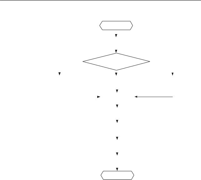
The following figure shows the process for installing an indoor AP.
Issue 12 (2015-08-05) |
Huawei Proprietary and Confidential |
15 |
|
Copyright © Huawei Technologies Co., Ltd. |
|
AP3x10xN&5x10xN&5x30xN&6x10xN&7x10xN |
|
Hardware Installation and Maintenance Guide |
2 AP Installation |
Figure 2-1 Installation flowchart of the AP3010DN-AGN, AP5010DN-AGN, AP5010SN-GN, AP6010DN-AGN, AP6010SN-GN, AP6310SN-GN, AP7110SN-GN and AP7110DN-AGN
|
|
|
|
|
|
|
|
Start |
|
|
|
|||||||||
|
|
|
|
|
|
|
|
|
|
|
|
|
|
|
|
|
|
|
|
|
|
|
|
|
|
|
|
|
|
|
|
|
|
|
|
|
|
|
|
|
|
|
|
|
|
|
|
|
|
|
|
|
|
|
|
|
|
|
|
|
|
|
|
|
|
|
Check before installation |
|
|
|
|
|
|||||||||||
|
To a T-rail |
|
|
|
|
|
|
|
|
|
|
|
|
|
|
|
|
Against the ceiling |
||
|
|
|
|
|
|
|
|
|
|
|
|
|||||||||
|
|
|
|
|
|
Determine the |
|
|||||||||||||
|
|
|
|
|
|
|
installation location |
|
|
|
||||||||||
|
|
|
|
|
|
|
|
|
|
Against the wall |
|
|
|
|||||||
|
|
|
|
|
|
|
|
|
|
|
|
|
||||||||
|
|
|
|
|
|
|
|
|
|
|
|
|||||||||
|
|
|
|
|
|
|
|
|
|
|
||||||||||
Fix the wall-mounting |
|
|
|
Fix the wall-mounting |
|
|
Fix the wall-mounting |
|||||||||||||
bracket to a T-rail |
|
|
|
bracket against the wall |
|
|
bracket against the ceiling |
|||||||||||||
|
|
|
|
|
|
|
|
|
|
|
|
|
|
|
|
|
|
|
|
|
|
|
|
|
|
|
|
|
|
|
|
|
|
|
|
|
|
|
|
|
|
|
|
|
|
|
|
|
|
Install the AP |
|
|
|
|
|
|
|
|
|
|
||
|
|
|
|
|
|
|
|
|
|
|
|
|
|
|
|
|
|
|||
|
|
|
|
|
|
|
|
|
|
|
|
|
|
|
|
|
|
|
|
|
|
|
|
|
|
|
|
|
|
|
|
|
|
|
|
|
|
||||
|
|
|
|
|
|
|
|
|
|
|
|
|
|
|
|
|
|
|
|
|
|
|
|
|
|
|
|
Connect the cable |
|
|
|
|
|
|
|
|
|||||
|
|
|
|
|
|
|
|
|
|
|
|
|
|
|
|
|
|
|||
|
|
|
|
|
|
|
|
|
|
|
|
|
|
|
|
|
||||
|
|
|
|
|
|
|
|
|
|
|
|
|
|
|
|
|
|
|
|
|
|
|
|
|
|
Connect the security lock |
|
|
|
|
|
|
|||||||||
|
|
|
|
|
|
|
|
to the lock hole |
|
|
|
|
|
|||||||
|
|
|
|
|
|
|
|
|
|
|
|
|
|
|||||||
|
|
|
|
|
|
|
|
|
|
|
|
|
|
|
|
|
|
|
|
|
|
|
|
|
|
Check after installation |
|
|
|
|
|
|
|
||||||||
|
|
|
|
|
|
|
|
|
|
|
|
|
|
|
|
|||||
|
|
|
|
|
|
|
|
|
|
|
|
|
|
|
|
|
|
|
|
|
|
|
|
|
|
|
|
|
|
|
|
|
|
|
|
|
|
|
|
|
|
|
|
|
|
|
|
|
|
Power on the AP |
|
|
|
|
|
|
|
|
|
|||
|
|
|
|
|
|
|
|
|
|
|
|
|
|
|
|
|
||||
|
|
|
|
|
|
|
|
|
|
|
|
|
|
|
|
|||||
|
|
|
|
|
|
|
|
End |
|
|
|
|||||||||
Issue 12 (2015-08-05) |
Huawei Proprietary and Confidential |
16 |
|
Copyright © Huawei Technologies Co., Ltd. |
|

AP3x10xN&5x10xN&5x30xN&6x10xN&7x10xN |
|
|
|
|
|
|
|
|
|
|
|
|
|
|||
Hardware Installation and Maintenance Guide |
|
|
|
|
|
|
|
|
|
|
|
2 AP Installation |
||||
Figure 2-2 Installation flowchart of the AP5030DN and AP5130DN |
||||||||||||||||
|
|
|
|
|
|
Start |
|
|
|
|
||||||
|
|
|
|
|
|
|
|
|
|
|
|
|
|
|
|
|
|
|
|
|
|
|
|
|
|
|
|
|
|
|
|
|
|
|
|
|
|
|
|
|
|
|
|
|
|
|
|
|
|
|
|
|
|
|
|
Check before installation |
|
|
|
|
|
|
|||||
|
|
|
|
|
|
|
|
|
|
|
|
|
|
|
|
|
|
|
|
|
|
|
|
|
|
|
|
|
|
|
|
|
|
|
|
|
|
|
|
|
|
|
|
|
|
|
|
|
|
|
|
|
|
|
|
|
Determine the |
|
|
|
|
|
|
|
|
||
|
|
|
|
|
|
installation location |
|
|
|
|
|
|
|
|||
|
|
To a T-rail |
|
|
|
|
|
|
|
|
|
|
Against the ceiling |
|||
|
|
|
|
Connect the cable |
|
|||||||||||
|
|
|
|
|
|
|
|
|
|
|||||||
|
|
|
|
|
|
|
|
Against the wall |
|
|
|
|
||||
|
|
|
|
|
|
|
|
|
|
|
|
|||||
|
|
|
|
|
|
|
|
|
|
|
|
|||||
|
Fix the wall-mounting |
|
|
|
Fix the wall-mounting |
|
|
|
Fix the wall-mounting |
|
||||||
|
bracket to a T-rail |
|
|
bracket against the wall |
|
|
bracket against the ceiling |
|
||||||||
|
|
|
|
|
|
|
|
|
|
|
|
|
|
|
|
|
Install the AP
Connect the security lock to the lock hole
Check after installation
Power on the AP
End
2.3 Unpacking the Equipment
Before unpacking the carton, ensure that the packing carton is intact and not damaged or soaked. Stop unpacking if the equipment is rusted or soggy. Then, investigate causes and contact the supplier.
After unpacking, check items in the carton against the packing list. If any item is missing, contact the supplier or agent.
Usually, the packing list contains the following items.
•AP device
•Power adapter (optional)
•Sheet metal mounting bracket4
•2.4 GHz antenna1
•5 GHz antenna1
•Dual-band antenna port2
•Expansion screws
Issue 12 (2015-08-05) |
Huawei Proprietary and Confidential |
17 |
|
Copyright © Huawei Technologies Co., Ltd. |
|
AP3x10xN&5x10xN&5x30xN&6x10xN&7x10xN |
|
Hardware Installation and Maintenance Guide |
2 AP Installation |
•OT terminal3
•Quick Start Guide
•Warranty card
•Qualification Card
•MAC address label
•SN label
 NOTE
NOTE
If the AT needs to be powered by an AC power supply, a PoE adapter must be independently purchased.
Pay attention to the following:
1.Three 2.4 GHz antennas and three 5 GHz antennas are contained in the AP7110DN-AGN carton, and three 2.4 GHz antennas are contained in the AP7110SN-GN carton. Cartons of other models do not contain these two types of antennas.
2.Only the AP5130DN carton contains three dual-band antennas.
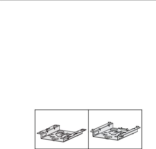
3.Only the AP6310SN-GN and AP7110 series have OT terminals delivered.
4.Currently, two types of sheet metal mounting brackets are available: sheet metal mounting bracket for the AP5030DN and AP5130DN, which has four mounting holes (see the left figure in Figure 2-3), and sheet metal mounting bracket for other indoor AP models, which has four mounting screws (see the right figure in Figure 2-3).
Figure 2-3 Sheet metal mounting brackets
2.4Determining the Installation Position
When determining the AP installation position, comply with the following rules:
•Try to reduce the number of obstacles, such as walls, between the AP and user terminals.
•Install the AP away from electronic devices that can cause radio interference, such as the microwave oven.
•Install the AP in a hidden position that does not affect daily lives and work of residents.
•Install the AP in a site that is free from leaking or dripping water, heavy dew, and humidity, and take protective measures to prevent water from flowing into the equipment along the cable.
Indoor APs are usually mounted on a wall or ceiling using sheet metal mounting brackets. The installation position is determined by the site survey. There must be at least 200 mm clearance between the cabling end of the AP and the wall. Figure 2-4 shows space requirements.
Issue 12 (2015-08-05) |
Huawei Proprietary and Confidential |
18 |
|
Copyright © Huawei Technologies Co., Ltd. |
|

AP3x10xN&5x10xN&5x30xN&6x10xN&7x10xN |
|
Hardware Installation and Maintenance Guide |
2 AP Installation |
Figure 2-4 Mounting an AP
Celling
≥200mm
≥200mm
≥200mm
Wall ≥200mm
Floor
2.5 Installing the AP
All cables of the AP5030DN and AP5130DN, including network cables, power supply cables, and console cables are routed towards the same direction. Before installing an AP on the mounting bracket, connect cables to the AP first. Figure 2-5 shows cable deployment and AP installation.
Figure 2-5 Cable deployment and AP installation
Issue 12 (2015-08-05) |
Huawei Proprietary and Confidential |
19 |
|
Copyright © Huawei Technologies Co., Ltd. |
|

AP3x10xN&5x10xN&5x30xN&6x10xN&7x10xN |
|
Hardware Installation and Maintenance Guide |
2 AP Installation |
 NOTE
NOTE
•The AP5030DN and AP5130DN must have cables connected first before installation. Except the two models, the procedures for installing the other models of indoor APs are the same unless otherwise stated. The following figures use the AP7110DN-AGN as an example.
•Remove the protective film on the AP surface before installation to prevent electrostatic discharge.
2.5.1Wall Mounting
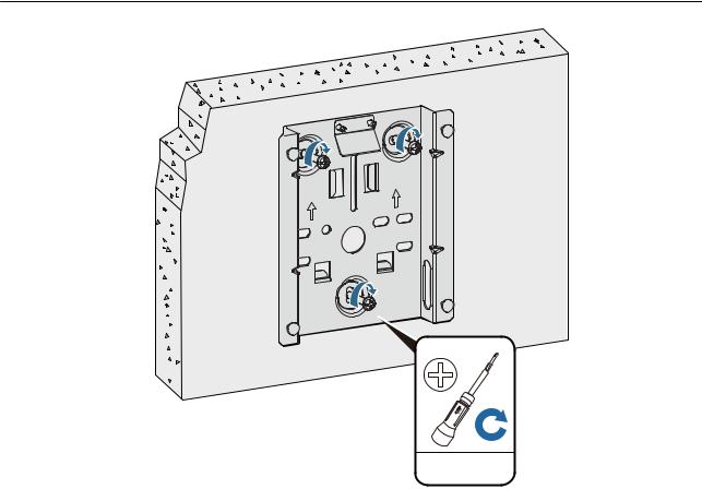
Mounting APs on a wall requires sheet metal mounting brackets and expansion screws. The procedures are as follows:
1.Fix the mounting bracket to the wall, adjust the installation position, and use the marker to mark the drilling positions where expansion screws are installed.
59mm
UP 
UP
85mm
2.Use a 6 mm drill bit to drill 25 mm to 30 mm deep holes in the drilling positions. Hammer the expansion tubes into the holes until the expansion tubes are completely embedded into the wall.
1 |
2 |
25mm~30mm |
3.Fix the mounting bracket to the wall and use the Phillips screwdriver to fasten three expansion screws into the expansion tubes.
Issue 12 (2015-08-05) |
Huawei Proprietary and Confidential |
20 |
|
Copyright © Huawei Technologies Co., Ltd. |
|
AP3x10xN&5x10xN&5x30xN&6x10xN&7x10xN |
|
Hardware Installation and Maintenance Guide |
2 AP Installation |
UP
UP
ST3.5
0.3N•m
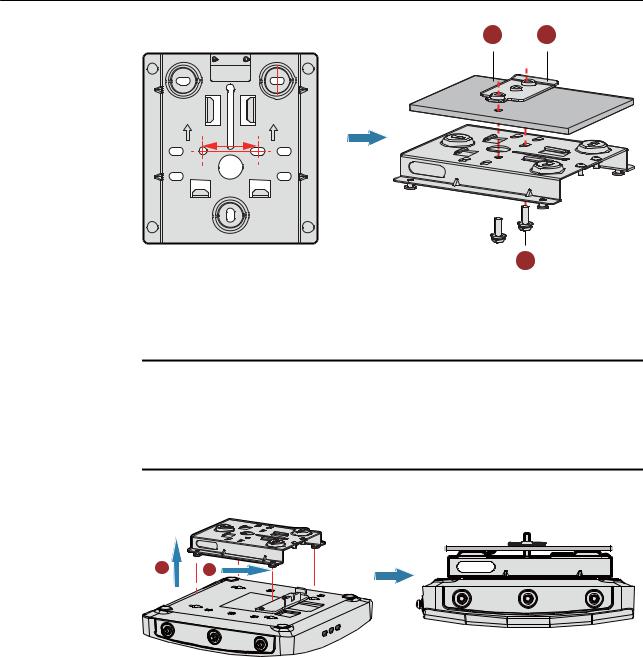
4.Align the mounting holes at the rear of the AP with the mounting screws on the mounting bracket and hang the AP on the bracket. Press the AP downwards to secure the AP on the wall.
Issue 12 (2015-08-05) |
Huawei Proprietary and Confidential |
21 |
|
Copyright © Huawei Technologies Co., Ltd. |
|

AP3x10xN&5x10xN&5x30xN&6x10xN&7x10xN |
|
Hardware Installation and Maintenance Guide |
2 AP Installation |
1
5G
LABEL
5G
5G
 NOTE
NOTE
2
The AP5030DN and AP5130DN use a different type of sheet metal mounting bracket than other APs. When installing an AP5030DN or AP5130DN, align the mounting screws at the rear of the AP with the mounting holes on the sheet metal mounting bracket and then press the AP downwards to secure the AP on the bracket.
2.5.2Ceiling Mounting
1.Fix a locking clip at the rear of the AP with two M3x6 screws. The locking clip prevents the AP hung on the mounting bracket from swaying.
 NOTE
NOTE
Only the AP6310SN-GN and AP7110 series require the locking clip during their installation.
1 2
LABEL
5G 5G 5G
1. M3x6 screw
SYS
Wireless |
Link |
|
LABEL
5G 5G 5G
2. Locking clip
SYS
Wireless |
Link |
|
2.Remove a ceiling tile, determine locations of mounting holes based on the distance between two installation holes on the mounting bracket, use a hammer drill to drill holes on the ceiling tile, and fix the mounting bracket to the ceiling tile.
Issue 12 (2015-08-05) |
Huawei Proprietary and Confidential |
22 |
|
Copyright © Huawei Technologies Co., Ltd. |
|
AP3x10xN&5x10xN&5x30xN&6x10xN&7x10xN |
|
Hardware Installation and Maintenance Guide |
2 AP Installation |
1 2
UP UP
35mm
3
1. Ceiling tile |
2. Adjustable buckle |
3. M4x30 screw |
|
|
|
 NOTICE
The screws provided for ceiling-mounting of APs are 30 mm long and can be used to fix an AP on a ceiling not thicker than 15 mm. To install APs on thicker ceilings, you need to purchase longer screws.
3.Hang the AP on the mounting screws by aligning the mounting holes at the rear of the AP with the mounting screws on the bracket and push the AP horizontally to secure the AP.
1 2
5G |
5G |
5G |
LABEL
SYS
5G 5G 5G
Wireless |
Link |
|
 NOTE
NOTE
•Ensure that the AP is correctly installed on the mounting bracket and there must be 200 mm space above and around the AP for maintenance.
•The AP5030DN and AP5130DN use a different type of sheet metal mounting bracket than other APs. When installing an AP5030DN or AP5130DN, align the mounting screws at the rear of the AP with the mounting holes on the sheet metal mounting bracket and then press the AP downwards to secure the AP on the bracket.
2.5.3T-rail Mounting
1.Fix a locking clip at the rear of the AP with two M3x6 screws. For installation methods, see step 1 in Ceiling Mounting.
Issue 12 (2015-08-05) |
Huawei Proprietary and Confidential |
23 |
|
Copyright © Huawei Technologies Co., Ltd. |
|
Loading...