


 Loading...
AP4050DN-E
Hardware Installation and
Maintenance Guide
Issue 05
Date 2018-02-02
HUAWEI TECHNOLOGIES CO., LTD.

Copyright © Huawei Technologies Co., Ltd. 2018. All rights reserved.
No part of this document may be reproduced or transmitted in any form or by any means without prior written consent of Huawei Technologies Co., Ltd.
Trademarks and Permissions


 and other Huawei trademarks are trademarks of Huawei Technologies Co., Ltd.
All other trademarks and trade names mentioned in this document are the property of their respective holders.
Notice
The purchased products, services and features are stipulated by the contract made between Huawei and the customer. All or part of the products, services and features described in this document may not be within the purchase scope or the usage scope. Unless otherwise specified in the contract, all statements, information, and recommendations in this document are provided "AS IS" without warranties, guarantees or representations of any kind, either express or implied.
The information in this document is subject to change without notice. Every effort has been made in the preparation of this document to ensure accuracy of the contents, but all statements, information, and recommendations in this document do not constitute a warranty of any kind, express or implied.
Huawei Technologies Co., Ltd.
Address: |
Huawei Industrial Base |
|
Bantian, Longgang |
|
Shenzhen 518129 |
|
People's Republic of China |
Website: |
http://e.huawei.com |
Issue 05 (2018-02-02) |
Huawei Proprietary and Confidential |
i |
|
Copyright © Huawei Technologies Co., Ltd. |
|
AP4050DN-E |
About This Document |
Hardware Installation and Maintenance Guide |
About This Document
Overview
This document describes hardware features of the AP4050DN-E and provides basic installation methods.
Intended Audience
This document is intended for network engineers responsible for WLAN installation and maintenance. You should have experience in network device installation and maintenance.
Symbol Conventions
The symbols that may be found in this document are defined as follows.
Symbol |
|
Description |
|
|
|
|
|
|
|
|
Indicates an imminently hazardous situation |
|
|
|
which, if not avoided, will result in death or |
|
|
|
serious injury. |
|
|
|
|
|
|
|
Indicates a potentially hazardous situation |
|
|
|
which, if not avoided, could result in death |
|
|
|
or serious injury. |
|
|
||
|
|
|
|
|
|
|
Indicates a potentially hazardous situation |
|
|
|
which, if not avoided, may result in minor |
|
|
|
or moderate injury. |
|
|
||
|
|
|
|
|
|
|
Indicates a potentially hazardous situation |
|
|
|
which, if not avoided, could result in |
|
|
|
equipment damage, data loss, performance |
|
|
||
|
|
|
deterioration, or unanticipated results. |
|
|
|
NOTICE is used to address practices not |
|
|
|
related to personal injury. |
|
|
|
|
Issue 05 (2018-02-02) |
Huawei Proprietary and Confidential |
ii |
|
Copyright © Huawei Technologies Co., Ltd. |
|

AP4050DN-E |
About This Document |
|
Hardware Installation and Maintenance Guide |
||
|
|
|
|
Symbol |
Description |
|
|
|
|
NOTE |
Calls attention to important information, |
|
|
best practices and tips. |
|
|
NOTE is used to address information not |
|
|
related to personal injury, equipment |
|
|
damage, and environment deterioration. |
|
|
|
Change History
Changes between document issues are cumulative. The latest document issue contains all changes made in previous issues.
Issue 05 (2018-02-02)
This version has the following updates:
The following information is modified:
•2.6.1 Installing the Device on a Wall
•2.6.2 Installing the Device on a Ceiling
•2.6.3 Installing the Device on a T-rail
•2.6.4 Removing an AP
Issue 04 (2017-08-31)
This version has the following updates:
The following information is modified:
•1.1 Device Structure
•2.3 Unpacking the Equipment
Issue 03 (2017-01-20)
This version has the following updates:
The following information is modified:
•2.6.1 Installing the Device on a Wall
•2.6.2 Installing the Device on a Ceiling
•2.6.3 Installing the Device on a T-rail
Issue 02 (2016-09-30)
This version has the following updates:
The following information is modified:
2.7 Cable Connection
Issue 05 (2018-02-02) |
Huawei Proprietary and Confidential |
iii |
|
Copyright © Huawei Technologies Co., Ltd. |
|

AP4050DN-E |
About This Document |
Hardware Installation and Maintenance Guide |
Issue 01 (2016-07-22)
Initial commercial release
Issue 05 (2018-02-02) |
Huawei Proprietary and Confidential |
iv |
|
Copyright © Huawei Technologies Co., Ltd. |
|

AP4050DN-E |
|
Hardware Installation and Maintenance Guide |
Contents |
Contents
About This Document..................................................................................................................... |
|
ii |
|
1 Product Overview.......................................................................................................................... |
|
1 |
|
1.1 |
Device Structure............................................................................................................................................................. |
|
1 |
1.2 |
Indicator Description...................................................................................................................................................... |
|
3 |
1.3 |
Basic Specifications........................................................................................................................................................ |
|
4 |
1.4 |
Ordering Information...................................................................................................................................................... |
|
5 |
2 AP Installation............................................................................................................................... |
|
6 |
|
2.1 |
Preparing for Installation................................................................................................................................................ |
|
6 |
2.2 |
Installation Flowchart..................................................................................................................................................... |
|
8 |
2.3 |
Unpacking the Equipment.............................................................................................................................................. |
|
8 |
2.4 |
Determining the Installation Position............................................................................................................................. |
|
9 |
2.5 |
Installing an IoT Card................................................................................................................................................... |
|
10 |
2.6 |
Installing the AP........................................................................................................................................................... |
|
14 |
2.6.1 Installing the Device on a Wall.................................................................................................................................. |
|
14 |
|
2.6.2 Installing the Device on a Ceiling............................................................................................................................. |
|
17 |
|
2.6.3 Installing the Device on a T-rail................................................................................................................................ |
|
18 |
|
2.6.4 Removing an AP........................................................................................................................................................ |
|
20 |
|
2.7 |
Cable Connection......................................................................................................................................................... |
|
20 |
2.8 |
Connecting the Security Lock...................................................................................................................................... |
|
23 |
2.9 |
Checking the Device After Installation........................................................................................................................ |
23 |
|
2.10 Powering on the AP.................................................................................................................................................... |
|
24 |
|
3 Logging In to the Device............................................................................................................ |
|
25 |
|
3.1 |
Logging In to the Device Using STelnet/Telnet........................................................................................................... |
25 |
|
3.2 |
Logging In to the Device Through the Web System.................................................................................................... |
27 |
|
3.3 |
Logging In to the Device Through the Console Port.................................................................................................... |
29 |
|
4 Hardware Failures....................................................................................................................... |
|
32 |
|
4.1 |
A Device Fails to Be Powered On................................................................................................................................ |
|
32 |
5 Appendix....................................................................................................................................... |
|
35 |
|
5.1 |
On-site Cable Assembly and Installation..................................................................................................................... |
35 |
|
5.1.1 Cable Assembly Precautions..................................................................................................................................... |
|
35 |
|
5.1.2 Assembling Power Cables......................................................................................................................................... |
|
36 |
|
Issue 05 (2018-02-02) |
Huawei Proprietary and Confidential |
v |
|
|
Copyright © Huawei Technologies Co., Ltd. |
|
|

AP4050DN-E |
|
|
Hardware Installation and Maintenance Guide |
Contents |
|
5.1.2.1 Assembling a DC 2-Pin Round Connector (A)...................................................................................................... |
36 |
|
5.1.2.2 Assembling a DC 2-Pin Round Connector (B)...................................................................................................... |
41 |
|
5.1.2.3 Assembling the OT Terminal and Power Cable..................................................................................................... |
47 |
|
5.1.2.4 Assembling the JG Terminal and Power Cable...................................................................................................... |
51 |
|
5.1.2.5 Assembling the Cord End Terminal and the Power Cable..................................................................................... |
53 |
|
5.1.3 Assembling Ethernet Cables...................................................................................................................................... |
|
56 |
5.1.3.1 Assembling the Shielded RJ45 Connector and Ethernet Cable.............................................................................. |
56 |
|
5.1.3.2 Assembling an Optimized Shielded RJ45 Connector and SFTP Network Cables................................................. |
62 |
|
5.1.3.3 Assembling an Integrated Shielded RJ45 Connector and SFTP Network Cables................................................. |
66 |
|
5.1.3.4 Assembling a Shielded RJ45 Connector and an FTP Network Cable.................................................................... |
70 |
|
5.1.3.5 Assembling an Unshielded RJ45 Connector and Ethernet Cable........................................................................... |
75 |
|
5.1.3.6 Checking the Appearance of Contact Strips........................................................................................................... |
77 |
|
5.1.3.7 Testing the Connection of Assembled Cables........................................................................................................ |
80 |
|
5.1.3.8 Common Network Cable Faults and Preventive Measures.................................................................................... |
83 |
|
5.1.4 Assembling Feeders................................................................................................................................................... |
|
84 |
5.1.4.1 Assembling the Straight Male Coaxial N Connector and the 1/2'' Feeder............................................................. |
84 |
|
5.1.4.2 Assembling a Straight Male Coaxial N Connector and an RG8U Feeder.............................................................. |
88 |
|
5.1.5 Installing Cable Accessories...................................................................................................................................... |
|
94 |
5.1.5.1 Precautions for Installing Cable Accessories......................................................................................................... |
94 |
|
5.1.5.2 Installing Power Adapters...................................................................................................................................... |
|
95 |
5.1.5.2.1 Installing the OT Terminal................................................................................................................................... |
|
95 |
5.1.5.2.2 Installing the Cord End Terminal........................................................................................................................ |
98 |
|
5.1.5.2.3 Installing a 2-Pin Round Connector and a DC Power Cable............................................................................... |
99 |
|
5.1.5.3 Installing Ethernet Adapters................................................................................................................................. |
|
102 |
5.1.5.3.1 Installing a Shielded Ethernet Connector.......................................................................................................... |
103 |
|
5.1.5.3.2 Installing an Unshielded Ethernet Connector.................................................................................................... |
104 |
|
5.1.5.4 Installing Fiber Connectors.................................................................................................................................. |
|
106 |
5.1.5.4.1 Cleaning Fiber Connectors................................................................................................................................ |
|
106 |
5.1.5.4.2 Installing an FC Fiber Connector...................................................................................................................... |
106 |
|
5.1.5.4.3 Installing an LC Fiber Connector...................................................................................................................... |
108 |
|
5.1.5.4.4 Installing the SC Fiber Connector..................................................................................................................... |
110 |
|
5.1.5.4.5 Installing an MPO Connector............................................................................................................................ |
|
111 |
5.1.6 Replacing the Mold of the Crimping Tool............................................................................................................... |
113 |
|
5.2 Environmental Requirements for Device Operation.................................................................................................. |
116 |
|
5.2.1 Environmental Requirements for an Equipment Room........................................................................................... |
116 |
|
5.2.1.1 Requirements for Selecting a Site for an Equipment Room................................................................................. |
116 |
|
5.2.1.2 Equipment Room Layout...................................................................................................................................... |
|
117 |
5.2.1.3 Construction Requirements for the Equipment Room.......................................................................................... |
118 |
|
5.2.1.4 Equipment Room Environment............................................................................................................................ |
|
119 |
5.2.1.5 Requirements for Corrosive Gases....................................................................................................................... |
120 |
|
5.2.1.6 Requirements for ESD Prevention....................................................................................................................... |
|
121 |
5.2.1.7 Electromagnetism Requirements for the Equipment Room................................................................................. |
121 |
|
Issue 05 (2018-02-02) |
Huawei Proprietary and Confidential |
vi |
Copyright © Huawei Technologies Co., Ltd. |
|
|

AP4050DN-E |
|
Hardware Installation and Maintenance Guide |
Contents |
5.2.1.8 Requirements for Lightning Proof Grounding..................................................................................................... |
121 |
5.2.2 Requirements for Power Supply.............................................................................................................................. |
123 |
5.2.2.1 Requirements for AC Power Supply.................................................................................................................... |
123 |
5.2.2.2 Recommendations for AC Power Supply............................................................................................................. |
124 |
5.2.2.3 Requirements for DC Power Supply.................................................................................................................... |
125 |
5.2.2.4 Recommendations for DC Power Supply............................................................................................................. |
125 |
5.3 Equipment Grounding Specifications......................................................................................................................... |
126 |
5.3.1 General Grounding Specifications........................................................................................................................... |
126 |
5.3.2 Grounding Specifications for an Equipment Room................................................................................................ |
126 |
5.3.3 Grounding Specifications for Devices..................................................................................................................... |
126 |
5.3.4 Grounding Specifications for Communications Power Supply............................................................................... |
127 |
5.3.5 Grounding Specifications for Signal Cables........................................................................................................... |
128 |
5.3.6 Specifications for Laying Out Grounding Cables................................................................................................... |
128 |
5.4 Engineering Labels for Cables................................................................................................................................... |
129 |
5.4.1 Introduction to Labels.............................................................................................................................................. |
129 |
5.4.1.1 Label Materials..................................................................................................................................................... |
129 |
5.4.1.2 Type and Structure................................................................................................................................................ |
130 |
5.4.1.3 Label Printing....................................................................................................................................................... |
131 |
5.4.1.4 Writing Labels...................................................................................................................................................... |
133 |
5.4.1.5 Attaching Labels................................................................................................................................................... |
134 |
5.4.1.6 Contents of Engineering Labels........................................................................................................................... |
136 |
5.4.1.7 Precautions for Using Engineering Labels........................................................................................................... |
136 |
5.4.2 Engineering Labels for Optical Fibers..................................................................................................................... |
137 |
5.4.2.1 Labels for the Optical Fibers Connecting Devices............................................................................................... |
137 |
5.4.2.2 Labels for the Optical Fibers Connecting the Device and an ODF...................................................................... |
138 |
5.4.3 Engineering Labels for Network Cables................................................................................................................. |
139 |
5.4.4 Engineering Labels for User Cables........................................................................................................................ |
141 |
5.4.5 Engineering Labels for Power Cables..................................................................................................................... |
142 |
5.4.5.1 Engineering Labels for DC Power Cables............................................................................................................ |
142 |
5.4.5.2 Engineering Labels for AC Power Cables............................................................................................................ |
143 |
5.5 Guide to Using Optical Modules................................................................................................................................ |
144 |
5.6 Fault Tag..................................................................................................................................................................... |
148 |
5.7 Installation Checklist.................................................................................................................................................. |
149 |
5.8 Guide to Making Drip Loops...................................................................................................................................... |
156 |
5.9 Power Adaptation Solution......................................................................................................................................... |
158 |
Issue 05 (2018-02-02) |
Huawei Proprietary and Confidential |
vii |
|
Copyright © Huawei Technologies Co., Ltd. |
|

AP4050DN-E |
1 Product Overview |
Hardware Installation and Maintenance Guide |
1Product Overview
About This Chapter
The AP4050DN-E has the following advantages:
•2x2 MIMO
•Good service support capabilities
•High reliability
•High security
•Simple network deployment
•Automatic AC discovery and configuration
•Real-time management and maintenance
In compliance with 802.11ac Wave 2, the AP4050DN-E can provide gigabit access for wireless users, greatly improving wireless user experience.
The AP4050DN-E provides basic 802.11n/ac WLANs for scenarios that can integrate enhanced applications (such as Bluetooth and RFID), such as shopping malls, supermarkets, healthcare, warehouse, manufacturing, and logistics. It provides flexible distribution options in different environments.
A cloud AP must be used together with a cloud server.
1.1Device Structure
1.2Indicator Description
1.3Basic Specifications
1.4Ordering Information
1.1Device Structure
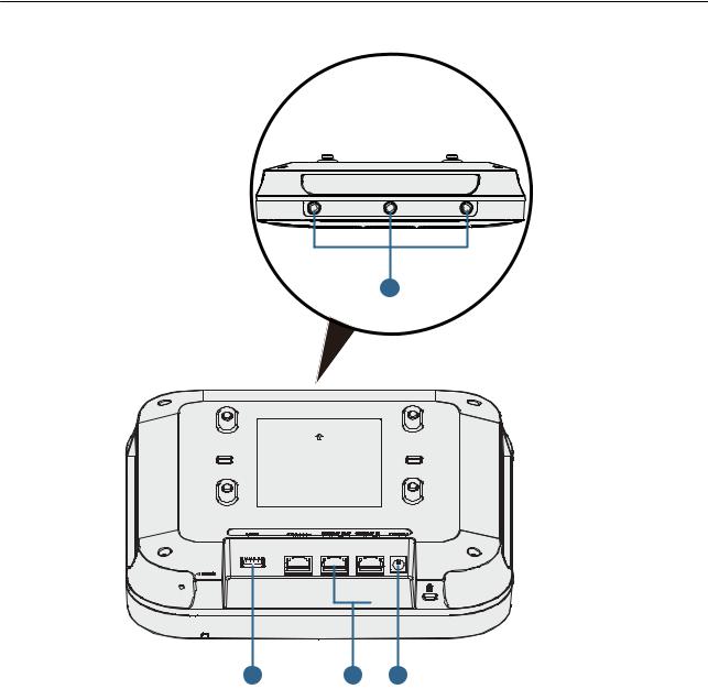
Figure 1-1 shows the appearance of the AP4050DN-E.
Issue 05 (2018-02-02) |
Huawei Proprietary and Confidential |
1 |
|
Copyright © Huawei Technologies Co., Ltd. |
|

AP4050DN-E |
1 Product Overview |
Hardware Installation and Maintenance Guide |
Figure 1-1 Appearance of the AP4050DN-E
8
1 |
2 |
3 |
4 |
5 |
6 |
7 |
Table 1-1 describes ports on the AP4050DN-E.
Table 1-1 Interface description
No. |
Name |
Description |
|
|
|
1 |
Default |
Reset button: restores factory settings and restarts the |
|
|
device if you hold down the button more than 3 seconds. |
|
|
|
2 |
USB port |
Connects to a USB flash drive to extend the storage space |
|
|
of the AP, and provides a maximum of 2.5 W power. |
|
|
|
3 |
Console |
Connects to a maintenance terminal for AP configuration |
|
|
and management. |
|
|
|
4 |
GE1/ |
10/100/1000M port: connects to the wired Ethernet and |
|
PoE_OUT |
supports PoE output. |
|
|
|
Issue 05 (2018-02-02) |
Huawei Proprietary and Confidential |
2 |
|
Copyright © Huawei Technologies Co., Ltd. |
|
AP4050DN-E |
|
1 Product Overview |
|
Hardware Installation and Maintenance Guide |
|||
|
|
|
|
|
No. |
Name |
Description |
|
|
|
|
|
5 |
GE0/PoE_IN |
10/100/1000M port: connects to the wired Ethernet and |
|
|
|
supports PoE input. |
|
|
|
|
|
6 |
DC 12V |
Connects a 12 V power adapter to the AP. |
|
|
|
|
|
7 |
Security slot |
Connects to a security lock. |
|
|
|
|
|
8 |
Radio port |
Connects an antenna to an IoT card through a radio cable. |
|
|
|
|
 NOTE
NOTE
•The AP supports the following power supply modes: PoE power supply and DC power supply.
•When the AP uses the DC power supply, use a power adapter for power supply; otherwise, the AP may be damaged.
•For power adapter models, see 5.9 Power Adaptation Solution.
1.2Indicator Description
The AP4050DN-E provides only a single indicator, as shown in Figure 1-2.
 NOTE
NOTE
Indicator colors may vary slightly at different temperature.
Figure 1-2 Indicator
Indicator
Table 1-2 Description about the single indicator
Type |
Color |
Status |
Description |
|
|
|
|
Default |
Green |
Steady on |
The AP is just powered on and the software is not |
status |
|
|
started yet. |
after |
|
|
|
power-on |
|
|
|
|
|
|
|
Issue 05 (2018-02-02) |
Huawei Proprietary and Confidential |
3 |
|
Copyright © Huawei Technologies Co., Ltd. |
|
AP4050DN-E |
|
|
1 Product Overview |
|
Hardware Installation and Maintenance Guide |
|
|||
|
|
|
|
|
|
Type |
Color |
Status |
Description |
|
|
|
|
|
|
Software |
Green |
Steady on |
After the system is reset and starts uploading the |
|
startup |
|
after |
software, the indicator blinks green once. Until the |
|
status |
|
blinking |
software is uploaded and started, the indicator |
|
|
|
once |
remains steady green. |
|
|
|
|
|
|
Running |
Green |
Blinking |
• The system is running properly, the Ethernet |
|
status |
|
once |
connection is normal, and STAs are associated |
|
|
|
every 2s |
with the AP. |
|
|
|
(0.5 Hz) |
• The system enters the Uboot CLI. |
|
|
|
|
|
|
|
|
|
|
|
|
|
Blinking |
The system is running properly, the Ethernet |
|
|
|
once |
connection is normal, and no STA is associated |
|
|
|
every 5s |
with the AP. The system is in low power |
|
|
|
(0.2 Hz) |
consumption state. |
|
|
|
|
|
|
Alarm |
Green |
Blinking |
• The software is being upgraded. |
|
|
|
once |
• After the software is loaded and started, the AP |
|
|
|
every |
|
|
|
|
requests to go online if it works in Fit AP or |
|
|
|
|
0.25s (4 |
|
|
|
|
cloud-based management mode. The indicator |
|
|
|
|
Hz) |
|
|
|
|
remains in this state before the AP successfully |
|
|
|
|
|
|
|
|
|
|
goes online. |
|
|
|
|
• The AP works in Fit AP or cloud-based |
|
|
|
|
management mode and fails to go online. |
|
|
|
|
|
|
Fault |
Red |
Steady on |
A fault that affects services has occurred, such as a |
|
|
|
|
DRAM detection failure or system software |
|
|
|
|
loading failure. The fault cannot be automatically |
|
|
|
|
rectified and must be rectified manually. |
|
|
|
|
|
1.3 Basic Specifications
Table 1-3 provides basic specifications of the AP4050DN-E.
Table 1-3 Basic specifications
Item |
|
Description |
|
|
|
Physical |
Dimensions (H x |
53 mm x 220 mm x 220 mm |
specifications |
W x D) |
|
|
|
|
|
Weight |
0.84 kg |
|
|
|
|
System memory |
• 256 MB DDR3L |
|
|
• 64 MB NOR FLASH |
|
|
|
Power |
Power input |
• DC: 12 V ± 10% |
specifications |
|
• PoE power supply: in compliance with IEEE |
|
|
|
|
|
802.3at |
|
|
|
Issue 05 (2018-02-02) |
Huawei Proprietary and Confidential |
4 |
|
Copyright © Huawei Technologies Co., Ltd. |
|

AP4050DN-E |
1 Product Overview |
Hardware Installation and Maintenance Guide |
Item |
|
Description |
|
|
|
|
Maximum power |
16.0 W (excluding the output power of the USB port, |
|
consumption |
IoT card, or PoE_OUT port) |
|
|
NOTE |
|
|
The actual maximum power consumption depends on local |
|
|
laws and regulations. |
|
|
|
Environment |
Operating |
• -60 m to +1800 m: -10°C to +50°C |
specifications |
temperature |
• 1800 m to 5000 m: Temperature decreases by 1°C |
|
|
|
|
|
every time the altitude increases 300 m. |
|
|
|
|
Storage |
-40°C to +70°C |
|
temperature |
|
|
|
|
|
Operating |
5% to 95% (non-condensing) |
|
humidity |
|
|
|
|
|
IP rating |
IP41 |
|
|
|
|
Atmospheric |
53 kPa to 106 kPa |
|
pressure |
|
|
|
|
1.4 Ordering Information
To place an order, contact technical support personnel.
Part Number |
Description |
|
|
50082944 |
AP4050DN-E Mainframe(11ac wave2,Dual Band,Built-in |
|
Antenna,BT,USB,PSE,IoT Slot) |
|
|
50083055 |
AP4050DN-E Mainframe Bundle (AP4050DN-E Mainframe*8) |
|
|
Issue 05 (2018-02-02) |
Huawei Proprietary and Confidential |
5 |
|
Copyright © Huawei Technologies Co., Ltd. |
|

AP4050DN-E |
2 AP Installation |
Hardware Installation and Maintenance Guide |
2AP Installation
About This Chapter
2.1Preparing for Installation
2.2Installation Flowchart
2.3Unpacking the Equipment
2.4Determining the Installation Position
2.5Installing an IoT Card
2.6Installing the AP
2.7Cable Connection
2.8Connecting the Security Lock
2.9Checking the Device After Installation
2.10Powering on the AP
2.1 Preparing for Installation
This section describes safety precautions and tool preparations for AP installation.
Safety Precautions
•Take proper measures to prevent injuries and device damage.
•Place the device in a dry and flat position away from any liquid and prevent the device from slipping.
•Keep the device clean.
•Do not put the device and tools in the aisles.
Issue 05 (2018-02-02) |
Huawei Proprietary and Confidential |
6 |
|
Copyright © Huawei Technologies Co., Ltd. |
|
AP4050DN-E |
2 AP Installation |
Hardware Installation and Maintenance Guide |
 CAUTION
Only the qualified personnel are permitted to install and remove the device and its accessories. Before installation and operation, read the safety precautions carefully.
Tool Preparation
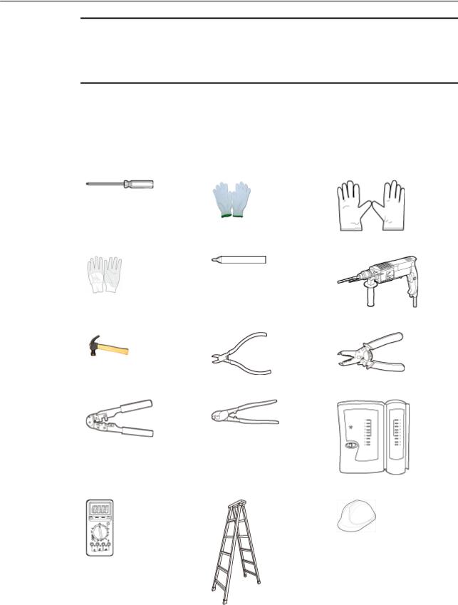
To install APs, prepare tools listed in Table 2-1.
Table 2-1 Tools
Phillips screwdriver |
Protective gloves |
ESD gloves |
|
|
|
Slip-proof glove |
Marker |
Hammer drill |
|
|
|
Claw hammer |
Diagonal pliers |
Wire stripper |
|
|
|
RJ45 crimping tool |
Cable cutter |
Network cable tester |
|
|
|
Multimeter |
Ladder |
Safety helmet |
|
|
|
Issue 05 (2018-02-02) |
Huawei Proprietary and Confidential |
7 |
|
Copyright © Huawei Technologies Co., Ltd. |
|

AP4050DN-E |
|
2 AP Installation |
|
Hardware Installation and Maintenance Guide |
|
||
|
|
|
|
|
Safety belt |
Anti-skid shoes |
- |
|
|
|
|
2.2 Installation Flowchart
The following figure shows the process for installing an AP.
Figure 2-1 Installation flowchart
2.3 Unpacking the Equipment
Before unpacking the carton, ensure that the packing carton is intact and not damaged or soaked. Stop unpacking if the equipment is rusted or soggy. Then, investigate causes and contact the supplier.
After unpacking, check items in the carton against the packing list. If any item is missing, contact the supplier or agent.
Issue 05 (2018-02-02) |
Huawei Proprietary and Confidential |
8 |
|
Copyright © Huawei Technologies Co., Ltd. |
|

AP4050DN-E |
2 AP Installation |
Hardware Installation and Maintenance Guide |
Usually, the packing list contains the following items.
•AP device
•Sheet metal mounting bracket
•Adjustable buckle
•Expansion screws
•Quick start guide
•Warranty card
•MAC address label
•SN label
 NOTE
NOTE
If a PoE adapter or a DC power adapter is required, you need to purchase it separately. For DC power adapter models, see 5.9 Power Adaptation Solution.
2.4 Determining the Installation Position
Indoor APs are usually mounted on a wall or ceiling using sheet metal mounting brackets. The installation position is determined by the site survey. There must be at least 200 mm clearance between the cabling end of the AP and the wall. Figure 2-2 shows space requirements.
Figure 2-2 Mounting an AP
Celling
≥200 mm
≥200 mm
≥200 mm
Wall |
≥200 mm |
|
Floor
When determining the AP installation position, comply with the following rules:
•Try to reduce the number of obstacles, such as walls, between the AP and user terminals.
Issue 05 (2018-02-02) |
Huawei Proprietary and Confidential |
9 |
|
Copyright © Huawei Technologies Co., Ltd. |
|

AP4050DN-E |
2 AP Installation |
Hardware Installation and Maintenance Guide |
•Place the AP far away from electronic devices that may produce radio interference, such as microwave ovens, other APs, antennas, and other radio communication devices. For details, see Table 2-2.
•Install the AP in a hidden position that does not affect daily lives and work of residents.
•Install the AP in a site that is free from leaking or dripping water, heavy dew, and humidity, and take protective measures to prevent water from flowing into the equipment along the cable.
•Do not install the AP in an environment with high temperature, dust, poisonous gases, flammable or explosive objects, electromagnetic interference (from a radar station, radio station, or substation), unstable voltage, violent shakes, or strong noise.
Table 2-2 General anti-interference requirements
Scenario |
Deployment Distance Requirement |
|
|
Indoor |
• There should be at least a 7 m distance between antennas. |
installation |
• The antennas should be placed at least 5 m from the 4G antennas of |
|
|
|
the carrier. |
|
• The antennas should be placed far away from electronic devices that |
|
may produce interference, such as microwave ovens. |
|
|
 NOTE
NOTE
If antennas are embedded into APs, the deployment distance requirements on the antennas are those on APs.
2.5 Installing an IoT Card
An AP4050DN-E has three IoT slots supporting ANT and RFID cards. An ANT card has only one radio port while an RFID card has two radio ports. Depending on card characteristics, IoT cards can be installed in one-cable per card or two-cable per card mode. Users need to install IoT cards onsite as required.
One-Cable per Card
In this mode, one to three ANT or RFID cards can be installed.
1.Remove the front cover of an AP.
Issue 05 (2018-02-02) |
Huawei Proprietary and Confidential |
10 |
|
Copyright © Huawei Technologies Co., Ltd. |
|

AP4050DN-E |
2 AP Installation |
Hardware Installation and Maintenance Guide |
2.Remove rubber plugs based on the number of IoT cards to be installed. One rubber plug maps one IoT card.
Rubber plugs
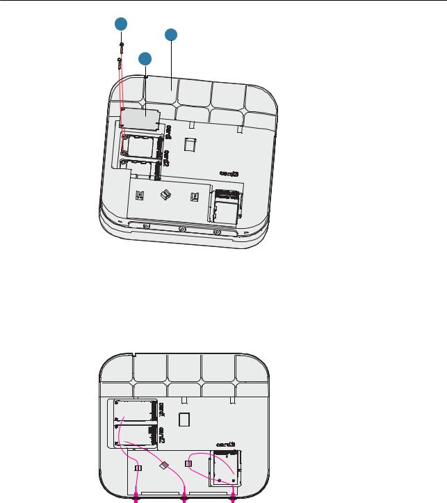
3.Place IoT cards in the slots and tighten the cards using M2x7 screws (with a tightening torque of 1.5 N•m). You are advised to start installation from the card1 slot.
Issue 05 (2018-02-02) |
Huawei Proprietary and Confidential |
11 |
|
Copyright © Huawei Technologies Co., Ltd. |
|
AP4050DN-E |
2 AP Installation |
Hardware Installation and Maintenance Guide |
3
1
2
1. AP4050DN-E |
2. IoT card |
3. M2x7 screws |
|
|
|
4.Install RF cables and sort cables following the instruction shown in the figure.
 NOTE
NOTE
•The diagonal size of a hexagon SMA connector must be less than or equal to 8 mm; otherwise, the cable cannot be installed.
5.Slide the cover back.
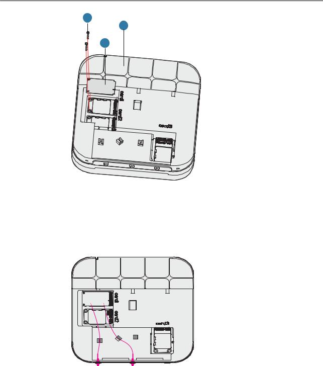
Two-Cable per Card
In this mode, only one RFID card can be installed. The card1 slot is preferentially used.
1.Remove the front cover of an AP.
Issue 05 (2018-02-02) |
Huawei Proprietary and Confidential |
12 |
|
Copyright © Huawei Technologies Co., Ltd. |
|
AP4050DN-E |
2 AP Installation |
Hardware Installation and Maintenance Guide |
2.Remove the two rubber plugs.
Rubber plugs
3.Place the card in the card1 slot and tighten the card using M2x7 screws (with a tightening torque of 1.5 N•m).
Issue 05 (2018-02-02) |
Huawei Proprietary and Confidential |
13 |
|
Copyright © Huawei Technologies Co., Ltd. |
|
AP4050DN-E |
2 AP Installation |
Hardware Installation and Maintenance Guide |
3
1
2
1. AP4050DN-E |
2. IoT card |
3. M2x7 screws |
|
|
|
4.Install RF cables and sort cables following the instruction shown in the figure.
 NOTE
NOTE
•The diagonal size of a hexagon SMA connector must be less than or equal to 8 mm; otherwise, the cable cannot be installed.
5.Slide the cover back.
2.6Installing the AP
 NOTE
NOTE
Remove the protective film on the surface before installation to prevent electrostatic discharge.
2.6.1 Installing the Device on a Wall
Issue 05 (2018-02-02) |
Huawei Proprietary and Confidential |
14 |
|
Copyright © Huawei Technologies Co., Ltd. |
|

AP4050DN-E |
2 AP Installation |
Hardware Installation and Maintenance Guide |
 NOTE
NOTE
A wall for installing the device needs to meet the following requirements:
•The wall can bear the weight of four times the total weight of the device and mounting bracket without damage.
•When the tightening torx of a screw reaches 5 N•m, the screw still properly works, without crack or damage on the wall.
Mounting kits and expansion bolts are required to install the AP on a wall. The procedures are as follows:
When fixing the sheet metal mounting bracket, ensure that the arrows point upwards on the  label.
1.Fix a mounting bracket to the wall against the wall and mark the drilling positions through holes of the bracket.
59 mm 


 mm85
mm85
2.Use a 6 mm drill bit to drill 25 mm to 30 mm deep holes in the drilling positions. Hammer the expansion tubes into the holes until the expansion tubes are completely embedded into the wall.
 Ø6
Ø6
25 mm~30 mm
3.Fix the mounting bracket to the wall and use the Phillips screwdriver to fasten three expansion screws into the expansion tubes.
Issue 05 (2018-02-02) |
Huawei Proprietary and Confidential |
15 |
|
Copyright © Huawei Technologies Co., Ltd. |
|

AP4050DN-E |
2 AP Installation |
Hardware Installation and Maintenance Guide |
ST3.5
1.7 N•m
4.Connect the cables. For details, see 2.7 Cable Connection.
5.Align the rubber feet of the device over the mounting slots on the mounting bracket and vertically push the AP to secure it. When the spring clip is popped up, push the AP downward until it snaps into place (you can hear a click).
a
b
Issue 05 (2018-02-02) |
Huawei Proprietary and Confidential |
16 |
|
Copyright © Huawei Technologies Co., Ltd. |
|

AP4050DN-E |
2 AP Installation |
Hardware Installation and Maintenance Guide |
 NOTE
NOTE
In a scenario with heavy vibrations, tighten the AP to the mounting bracket using M4x30 screws with a torque of 1.4N•m. This prevents the AP falling off from due to vibrations. In normal scenarios, you do not need to install these screws.
2.6.2 Installing the Device on a Ceiling
 NOTE
NOTE
A ceiling needs to bear the weight of four times the total weight of the device and mounting bracket without damage.
1.Remove a ceiling tile, determine locations of mounting holes based on the distance between two installation holes on the mounting bracket, use a hammer drill to drill holes on the ceiling tile, and fix the mounting bracket to the ceiling tile(with a tightening torque of 1.4 N•m).
The screws provided for ceiling-mounting of APs are 30 mm long and can be used to fix an AP on a ceiling no thicker than 15 mm. To install APs on thicker ceilings, you need to purchase longer screws.
1
2
47 mm
3
1. Ceiling tile |
2. Adjustable buckle |
3. M4x30 screw |
|
|
|
Issue 05 (2018-02-02) |
Huawei Proprietary and Confidential |
17 |
|
Copyright © Huawei Technologies Co., Ltd. |
|

AP4050DN-E |
2 AP Installation |
Hardware Installation and Maintenance Guide |
2.Connect the cables. For details, see 2.7 Cable Connection.
3.Align the rubber feet of the device over the mounting slots on the mounting bracket and vertically push the AP to secure it. When the spring clip is popped up, push the AP horizontally until it snaps into place (you can hear a click).
b
a
c
 NOTE
NOTE
•Ensure that the AP is correctly installed on the mounting bracket and there is 200 mm space above and around the AP for maintenance.
•In a scenario with heavy vibrations, tighten the AP to the mounting bracket using M4x30 screws with a torque of 1.4N•m. This prevents the AP falling off from due to vibrations. In normal scenarios, you do not need to install these screws.
2.6.3Installing the Device on a T-rail
A T-rail needs to bear the weight of four times the total weight of the device and mounting bracket without damage. Figure 2-3 shows the T-rail dimensions requirements (t: thickness; w: width).
Figure 2-3 Section of a T-rail
0.6 mm ≤ t ≤ 1.0 mm
19 mm ≤ w ≤ 29 mm
Issue 05 (2018-02-02) |
Huawei Proprietary and Confidential |
18 |
|
Copyright © Huawei Technologies Co., Ltd. |
|

AP4050DN-E |
2 AP Installation |
Hardware Installation and Maintenance Guide |
1.Remove two ceiling tiles around the T-rail, use screws to fix the adjustable buckle to the mounting bracket, hook the adjustable buckle to the T-rail, and secure the screw on the adjustable buckle to fasten the mounting bracket and T-rail.
3
1
4
2
1. T-rail 2. M4x30 Screw 3. Adjustable buckle 4. Sheet metal mounting bracket
2.Connect the cables. For details, see 2.7 Cable Connection.
3.Align the rubber feet of the device over the mounting slots on the mounting bracket and vertically push the AP to secure it. When the spring clip is popped up, push the AP horizontally until it snaps into place (you can hear a click).
b
a
c
Issue 05 (2018-02-02) |
Huawei Proprietary and Confidential |
19 |
|
Copyright © Huawei Technologies Co., Ltd. |
|

AP4050DN-E |
2 AP Installation |
Hardware Installation and Maintenance Guide |
 NOTE
NOTE
•Before fixing the adjustable buckle with a screw, adjust the buckle to a proper position based on the T-rail width.
•Ensure that the AP is correctly installed on the mounting bracket and there is 200 mm space above and around the AP for maintenance.
•In a scenario with heavy vibrations, tighten the AP to the mounting bracket using M4x30 screws with a torque of 1.4N•m. This prevents the AP falling off from due to vibrations. In normal scenarios, you do not need to install these screws.
2.6.4Removing an AP
Flip the spring clip on the mounting bracket and slip the AP towards the spring clip. Release the spring clip until the rubber feet of the AP enter the mounting keyholes. Remove the AP from the mounting bracket.
Figure 2-4 Removing an AP
c
a
b
 NOTE
NOTE
If a captive screw is installed, remove the screw and then follow the preceding steps to uninstall the AP.
2.7 Cable Connection
Table 2-3 describes the cable connections.
Issue 05 (2018-02-02) |
Huawei Proprietary and Confidential |
20 |
|
Copyright © Huawei Technologies Co., Ltd. |
|
AP4050DN-E |
2 AP Installation |
Hardware Installation and Maintenance Guide |
Figure 2-5 Appearance of the AP4050DN-E
4
|
|
|
|
|
|
|
|
|
|
|
|
|
|
|
|
|
|
|
|
|
|
|
|
|
|
|
|
|
|
|
|
|
|
|
|
|
1 |
|
|
|
|
|
|
|
2 |
|
|
|
|
|
|||
|
|
|
|
|
|
|
|
|
|
3 |
|||||||
Table 2-3 Cable connections |
|
|
|
|
|
|
|
|
|||||||||
|
|
|
|
|
|
|
|
|
|
|
|
|
|
|
|
|
|
No. |
Cable or Device |
|
Description |
||||||||||||||
|
|
|
|
|
|
|
|
|
|
|
|
|
|
|
|
|
|
1 |
USB flash drive |
|
Connects to a USB flash drive to extend the storage space |
||||||||||||||
|
|
|
|
|
|
|
|
|
|
|
of the AP, and provides a maximum of 2.5 W power. |
||||||
|
|
|
|
|
|
|
|
|
|
|
|
|
|
|
|
|
|
Issue 05 (2018-02-02) |
Huawei Proprietary and Confidential |
21 |
|
Copyright © Huawei Technologies Co., Ltd. |
|

AP4050DN-E |
|
2 AP Installation |
|
Hardware Installation and Maintenance Guide |
|||
|
|
|
|
|
No. |
Cable or Device |
Description |
|
|
|
|
2Network cable • The service network cable and PoE input cable cannot
be connected to the console port. Otherwise, the AP may be damaged when using PoE power supply.
|
|
• If the AP needs to connect to the Ethernet, ensure that |
|
|
the Ethernet cable is working properly. If the Ethernet |
|
|
cable is not working properly, for example, RJ45 |
|
|
connectors are short-circuited, the AP may fail to be |
|
|
powered on or fail to work. Before connecting an |
|
|
Ethernet cable to the AP, use the cable test tool to |
|
|
check whether the cable is qualified. If the cable is |
|
|
unqualified, replace it. |
|
|
NOTICE |
|
|
• Do not insert a PoE input cable into the GE1/PoE_OUT port. |
|
|
• CAT5e cables or higher must be used. |
|
|
• The length of a cable in the GE0/PoE_IN interface cannot |
|
|
exceed 100 m. |
|
|
• The length of a cable cannot exceed 40 m when the GE1/ |
|
|
PoE_OUT port has PoE output and cannot exceed 100 m |
|
|
when there is no PoE output. |
|
|
• The GE1/PoE_OUT port of an AP can provide power output |
|
|
only works in 802.3at PoE mode. The output power varies at |
|
|
different connection status: |
|
|
• The maximum output power is 7 W when no IoT card is |
|
|
connected to the AP and the USB port is not used. |
|
|
• The maximum output power is 5.5 W when only one IoT |
|
|
card is connected to the AP and the USB port is not used. |
|
|
• The PoE_OUT function is automatically disabled when |
|
|
two or more IoT cards are connected to the AP or the |
|
|
USB port is used. |
|
|
|
3 |
DC power adapter |
When the AP uses the DC power supply, use a power |
|
|
adapter for power supply; otherwise, the AP may be |
|
|
damaged. |
|
|
|
4 |
RF cable |
Connects to an IoT card or an antenna. |
 NOTE
NOTE
The AP is powered by either the DC power supply or PoE power supply that backs up each other.
When installing a cable, you must make a drip loop to prevent water from flowing into devices along the cable. For the method of making the drip loop, see 5.8 Guide to Making Drip Loops.
Pay attention to the following points when bundling the cables:
•Different types of cables must be separately routed with the minimum spacing of 30 mm and cannot be entangled or crossed. Cables should be parallel or separated using dedicated separators.
•Bundled cables are closely arranged, straight, tidy, and undamaged.
Issue 05 (2018-02-02) |
Huawei Proprietary and Confidential |
22 |
|
Copyright © Huawei Technologies Co., Ltd. |
|
Loading...