


 Loading...
User Guide
hp rp7405/7410 Servers
Third Edition
Manufacturing Part Number: A6752-96008
21102
USA
© Copyright 2002

Legal Notices
The information in this document is subject to change without notice.
Hewlett-Packard makes no warranty of any kind with regard to this manual, including, but not limited to, the implied warranties of merchantability and fitness for a particular purpose. Hewlett-Packard shall not be held liable for errors contained herein or direct, indirect, special, incidental or consequential damages in connection with the furnishing, performance, or use of this material.
Restricted Rights Legend. Use, duplication or disclosure by the U.S. Government is subject to restrictions as set forth in subparagraph (c) (1) (ii) of the Rights in Technical Data and Computer Software clause at DFARS 252.227-7013 for DOD agencies, and subparagraphs (c) (1) and (c) (2) of the Commercial Computer Software Restricted Rights clause at FAR 52.227-19 for other agencies.
HEWLETT-PACKARD COMPANY 3000 Hanover Street Palo Alto, California 94304 U.S.A.
Copyright Notices. ©copyright 1983-2002 Hewlett-Packard Company, all rights reserved.
Reproduction, adaptation, or translation of this document without prior written permission is prohibited, except as allowed under the copyright laws.
ii

Contents
1. Introduction
hp rp7405/rp7410 Overview . . . . . . . . . . . . . . . . . . . . . . . . . . . . . . . . . . . . . . . . . . . . . . . . . . . . . . . . . . . . 2 Cell Board . . . . . . . . . . . . . . . . . . . . . . . . . . . . . . . . . . . . . . . . . . . . . . . . . . . . . . . . . . . . . . . . . . . . . . . . . 3 System Backplane. . . . . . . . . . . . . . . . . . . . . . . . . . . . . . . . . . . . . . . . . . . . . . . . . . . . . . . . . . . . . . . . . . . 4 I/O Subsystem . . . . . . . . . . . . . . . . . . . . . . . . . . . . . . . . . . . . . . . . . . . . . . . . . . . . . . . . . . . . . . . . . . . . . . 4 hp rp7405 Servers . . . . . . . . . . . . . . . . . . . . . . . . . . . . . . . . . . . . . . . . . . . . . . . . . . . . . . . . . . . . . . . . . . . . 5 Detailed hp rp7405/rp7410 Description . . . . . . . . . . . . . . . . . . . . . . . . . . . . . . . . . . . . . . . . . . . . . . . . . . . 6 Cell Board . . . . . . . . . . . . . . . . . . . . . . . . . . . . . . . . . . . . . . . . . . . . . . . . . . . . . . . . . . . . . . . . . . . . . . . . . 7 Cells and nPartitions . . . . . . . . . . . . . . . . . . . . . . . . . . . . . . . . . . . . . . . . . . . . . . . . . . . . . . . . . . . . . . . . 9 System Backplane. . . . . . . . . . . . . . . . . . . . . . . . . . . . . . . . . . . . . . . . . . . . . . . . . . . . . . . . . . . . . . . . . . 11 I/O Subsystem . . . . . . . . . . . . . . . . . . . . . . . . . . . . . . . . . . . . . . . . . . . . . . . . . . . . . . . . . . . . . . . . . . . . . 11 Package Description . . . . . . . . . . . . . . . . . . . . . . . . . . . . . . . . . . . . . . . . . . . . . . . . . . . . . . . . . . . . . . . . 14
2. Installation
Unpacking the Server . . . . . . . . . . . . . . . . . . . . . . . . . . . . . . . . . . . . . . . . . . . . . . . . . . . . . . . . . . . . . . . . 18 Unpacking a Racked Server . . . . . . . . . . . . . . . . . . . . . . . . . . . . . . . . . . . . . . . . . . . . . . . . . . . . . . . . . . 18 Unpacking a Non-Racked Server . . . . . . . . . . . . . . . . . . . . . . . . . . . . . . . . . . . . . . . . . . . . . . . . . . . . . . 22 Installing Server Into the Rack . . . . . . . . . . . . . . . . . . . . . . . . . . . . . . . . . . . . . . . . . . . . . . . . . . . . . . . 28 Installing the Cable Management Arm (CMA). . . . . . . . . . . . . . . . . . . . . . . . . . . . . . . . . . . . . . . . . . . 29 Installing Add-On Products . . . . . . . . . . . . . . . . . . . . . . . . . . . . . . . . . . . . . . . . . . . . . . . . . . . . . . . . . . 30
Connecting AC Input Power . . . . . . . . . . . . . . . . . . . . . . . . . . . . . . . . . . . . . . . . . . . . . . . . . . . . . . . . . . . 34 MP Core I/O Connections . . . . . . . . . . . . . . . . . . . . . . . . . . . . . . . . . . . . . . . . . . . . . . . . . . . . . . . . . . . . . 36 MP/SCSI Connections. . . . . . . . . . . . . . . . . . . . . . . . . . . . . . . . . . . . . . . . . . . . . . . . . . . . . . . . . . . . . . . 36 LAN/SCSI Connections . . . . . . . . . . . . . . . . . . . . . . . . . . . . . . . . . . . . . . . . . . . . . . . . . . . . . . . . . . . . . 36 Management Processor Access. . . . . . . . . . . . . . . . . . . . . . . . . . . . . . . . . . . . . . . . . . . . . . . . . . . . . . . . 36 Setting Up the CE Tool (PC) . . . . . . . . . . . . . . . . . . . . . . . . . . . . . . . . . . . . . . . . . . . . . . . . . . . . . . . . . 37 Standby Power and Logging in to the MP . . . . . . . . . . . . . . . . . . . . . . . . . . . . . . . . . . . . . . . . . . . . . . . 38 Configuring LAN Information for the MP. . . . . . . . . . . . . . . . . . . . . . . . . . . . . . . . . . . . . . . . . . . . . . . 40 Verifying Presence of the Cell Boards . . . . . . . . . . . . . . . . . . . . . . . . . . . . . . . . . . . . . . . . . . . . . . . . . . 42 Powering On the hp rp7405/rp7410 Server . . . . . . . . . . . . . . . . . . . . . . . . . . . . . . . . . . . . . . . . . . . . . . . 44 Selecting a Boot Partition using the Management Processor . . . . . . . . . . . . . . . . . . . . . . . . . . . . . . . . 45 Verifying the System Configuration using Boot Console Handler (BCH) . . . . . . . . . . . . . . . . . . . . . . . 46 Booting HP-UX using Boot Console Handler (BCH) . . . . . . . . . . . . . . . . . . . . . . . . . . . . . . . . . . . . . . . . 47
3. Troubleshooting
Common Installation Problems. . . . . . . . . . . . . . . . . . . . . . . . . . . . . . . . . . . . . . . . . . . . . . . . . . . . . . . . . 50 The Server Does Not Power On . . . . . . . . . . . . . . . . . . . . . . . . . . . . . . . . . . . . . . . . . . . . . . . . . . . . . . . 51 The Server Powers On But Then Shuts Down with a Fault Light . . . . . . . . . . . . . . . . . . . . . . . . . . . 51 hp rp7405/rp7410 LED Indicators . . . . . . . . . . . . . . . . . . . . . . . . . . . . . . . . . . . . . . . . . . . . . . . . . . . . . 51
4. Removal and Replacement
Shutting Down nPartitions and Powering Off Hardware Components . . . . . . . . . . . . . . . . . . . . . . . . . 58
Shutting Down an nPartition. . . . . . . . . . . . . . . . . . . . . . . . . . . . . . . . . . . . . . . . . . . . . . . . . . . . . . . . . 58
Powering Off Hardware Components . . . . . . . . . . . . . . . . . . . . . . . . . . . . . . . . . . . . . . . . . . . . . . . . . . 59
Removing and Replacing the Top Cover . . . . . . . . . . . . . . . . . . . . . . . . . . . . . . . . . . . . . . . . . . . . . . . . . . 61
Removing the Top Cover. . . . . . . . . . . . . . . . . . . . . . . . . . . . . . . . . . . . . . . . . . . . . . . . . . . . . . . . . . . . . 62
iii

Contents
Replacing the Top Cover. . . . . . . . . . . . . . . . . . . . . . . . . . . . . . . . . . . . . . . . . . . . . . . . . . . . . . . . . . . . . 62 Removing and Replacing a Disk Drive . . . . . . . . . . . . . . . . . . . . . . . . . . . . . . . . . . . . . . . . . . . . . . . . . . . 63 Removing a Disk Drive. . . . . . . . . . . . . . . . . . . . . . . . . . . . . . . . . . . . . . . . . . . . . . . . . . . . . . . . . . . . . . 64 Replacing a Disk Drive . . . . . . . . . . . . . . . . . . . . . . . . . . . . . . . . . . . . . . . . . . . . . . . . . . . . . . . . . . . . . . 64 Removing and Replacing a CD/DVD Drive. . . . . . . . . . . . . . . . . . . . . . . . . . . . . . . . . . . . . . . . . . . . . . . . 66 Removing a CD/DVD Drive . . . . . . . . . . . . . . . . . . . . . . . . . . . . . . . . . . . . . . . . . . . . . . . . . . . . . . . . . . 67 Replacing a CD/DVD . . . . . . . . . . . . . . . . . . . . . . . . . . . . . . . . . . . . . . . . . . . . . . . . . . . . . . . . . . . . . . . 68 Removing and Replacing a Front Smart Fan Assembly . . . . . . . . . . . . . . . . . . . . . . . . . . . . . . . . . . . . . 69 Removing a Front Smart Fan Assembly . . . . . . . . . . . . . . . . . . . . . . . . . . . . . . . . . . . . . . . . . . . . . . . . 70 Replacing a Front Smart Fan Assembly . . . . . . . . . . . . . . . . . . . . . . . . . . . . . . . . . . . . . . . . . . . . . . . . 70 Removing and Replacing a Rear Smart Fan Assembly . . . . . . . . . . . . . . . . . . . . . . . . . . . . . . . . . . . . . . 71 Removing a Rear Smart Fan Assembly . . . . . . . . . . . . . . . . . . . . . . . . . . . . . . . . . . . . . . . . . . . . . . . . . 72 Replacing a Rear Smart Fan Assembly . . . . . . . . . . . . . . . . . . . . . . . . . . . . . . . . . . . . . . . . . . . . . . . . . 72 Removing and Replacing a PCI Smart Fan Assembly . . . . . . . . . . . . . . . . . . . . . . . . . . . . . . . . . . . . . . . 73 Removing a PCI Smart Fan Assembly. . . . . . . . . . . . . . . . . . . . . . . . . . . . . . . . . . . . . . . . . . . . . . . . . . 74 Replacing a PCI Smart Fan Assembly. . . . . . . . . . . . . . . . . . . . . . . . . . . . . . . . . . . . . . . . . . . . . . . . . . 74 Removing and Replacing a Bulk Power Supply . . . . . . . . . . . . . . . . . . . . . . . . . . . . . . . . . . . . . . . . . . . . 75 Removing a BPS . . . . . . . . . . . . . . . . . . . . . . . . . . . . . . . . . . . . . . . . . . . . . . . . . . . . . . . . . . . . . . . . . . . 76 Replacing a BPS . . . . . . . . . . . . . . . . . . . . . . . . . . . . . . . . . . . . . . . . . . . . . . . . . . . . . . . . . . . . . . . . . . . 76 Removing and Replacing a PCI Power Module (Brick) . . . . . . . . . . . . . . . . . . . . . . . . . . . . . . . . . . . . . . 77 Removing a PCI Power Module (Brick) . . . . . . . . . . . . . . . . . . . . . . . . . . . . . . . . . . . . . . . . . . . . . . . . . 78 Replacing a PCI Power Module (Brick) . . . . . . . . . . . . . . . . . . . . . . . . . . . . . . . . . . . . . . . . . . . . . . . . . 78 Removing and Replacing the PCI Voltage Regulator Modules . . . . . . . . . . . . . . . . . . . . . . . . . . . . . . . . 79 Removing PCI VRM . . . . . . . . . . . . . . . . . . . . . . . . . . . . . . . . . . . . . . . . . . . . . . . . . . . . . . . . . . . . . . . . 79 Replacing the PCI VRM . . . . . . . . . . . . . . . . . . . . . . . . . . . . . . . . . . . . . . . . . . . . . . . . . . . . . . . . . . . . . 79 Removing and Replacing a PCI Card . . . . . . . . . . . . . . . . . . . . . . . . . . . . . . . . . . . . . . . . . . . . . . . . . . . . 81 Removing and Replacing a PCI Card . . . . . . . . . . . . . . . . . . . . . . . . . . . . . . . . . . . . . . . . . . . . . . . . . . 81 Removing and Replacing the Mass Storage Backplane . . . . . . . . . . . . . . . . . . . . . . . . . . . . . . . . . . . . . . 84 Removing the Backplane . . . . . . . . . . . . . . . . . . . . . . . . . . . . . . . . . . . . . . . . . . . . . . . . . . . . . . . . . . . . 84 Replacing the Backplane . . . . . . . . . . . . . . . . . . . . . . . . . . . . . . . . . . . . . . . . . . . . . . . . . . . . . . . . . . . . 86 Removing and Replacing a MP/SCSI Board . . . . . . . . . . . . . . . . . . . . . . . . . . . . . . . . . . . . . . . . . . . . . . . 87 Removing a MP/SCSI board . . . . . . . . . . . . . . . . . . . . . . . . . . . . . . . . . . . . . . . . . . . . . . . . . . . . . . . . . . 88 Replacing a MP/SCSI Board . . . . . . . . . . . . . . . . . . . . . . . . . . . . . . . . . . . . . . . . . . . . . . . . . . . . . . . . . 88
A.Replaceable Parts
B.System Specifications
Dimensions and Weights . . . . . . . . . . . . . . . . . . . . . . . . . . . . . . . . . . . . . . . . . . . . . . . . . . . . . . . . . . . . . . 94
Electrical Specifications. . . . . . . . . . . . . . . . . . . . . . . . . . . . . . . . . . . . . . . . . . . . . . . . . . . . . . . . . . . . . . . 95
Grounding . . . . . . . . . . . . . . . . . . . . . . . . . . . . . . . . . . . . . . . . . . . . . . . . . . . . . . . . . . . . . . . . . . . . . . . . 95
Circuit Breaker . . . . . . . . . . . . . . . . . . . . . . . . . . . . . . . . . . . . . . . . . . . . . . . . . . . . . . . . . . . . . . . . . . . . 95
System AC Power Specifications . . . . . . . . . . . . . . . . . . . . . . . . . . . . . . . . . . . . . . . . . . . . . . . . . . . . . . 95
Environmental Specifications . . . . . . . . . . . . . . . . . . . . . . . . . . . . . . . . . . . . . . . . . . . . . . . . . . . . . . . . . . 97
Temperature and Humidity . . . . . . . . . . . . . . . . . . . . . . . . . . . . . . . . . . . . . . . . . . . . . . . . . . . . . . . . . . 97
Cooling. . . . . . . . . . . . . . . . . . . . . . . . . . . . . . . . . . . . . . . . . . . . . . . . . . . . . . . . . . . . . . . . . . . . . . . . . . . 97
Typical Power Dissipation and Cooling . . . . . . . . . . . . . . . . . . . . . . . . . . . . . . . . . . . . . . . . . . . . . . . . . 98
iv

Contents
Acoustic Noise Specification. . . . . . . . . . . . . . . . . . . . . . . . . . . . . . . . . . . . . . . . . . . . . . . . . . . . . . . . . . 98
Air Flow . . . . . . . . . . . . . . . . . . . . . . . . . . . . . . . . . . . . . . . . . . . . . . . . . . . . . . . . . . . . . . . . . . . . . . . . . . 98
C. Site Preparation
Electrical Considerations. . . . . . . . . . . . . . . . . . . . . . . . . . . . . . . . . . . . . . . . . . . . . . . . . . . . . . . . . . . . . 102 Electrical Load Requirements (Circuit Breaker Sizing) . . . . . . . . . . . . . . . . . . . . . . . . . . . . . . . . . . . . 103 Power Quality. . . . . . . . . . . . . . . . . . . . . . . . . . . . . . . . . . . . . . . . . . . . . . . . . . . . . . . . . . . . . . . . . . . . . . 104 Sources of Electrical Disturbances . . . . . . . . . . . . . . . . . . . . . . . . . . . . . . . . . . . . . . . . . . . . . . . . . . . 104 Power System Protection . . . . . . . . . . . . . . . . . . . . . . . . . . . . . . . . . . . . . . . . . . . . . . . . . . . . . . . . . . . 104 Distribution Hardware . . . . . . . . . . . . . . . . . . . . . . . . . . . . . . . . . . . . . . . . . . . . . . . . . . . . . . . . . . . . . . 105 Wire Selection . . . . . . . . . . . . . . . . . . . . . . . . . . . . . . . . . . . . . . . . . . . . . . . . . . . . . . . . . . . . . . . . . . . . 105 Raceway Systems (electrical conduits) . . . . . . . . . . . . . . . . . . . . . . . . . . . . . . . . . . . . . . . . . . . . . . . . 105 Building Distribution . . . . . . . . . . . . . . . . . . . . . . . . . . . . . . . . . . . . . . . . . . . . . . . . . . . . . . . . . . . . . . 105 Power Routing. . . . . . . . . . . . . . . . . . . . . . . . . . . . . . . . . . . . . . . . . . . . . . . . . . . . . . . . . . . . . . . . . . . . 105 Grounding Systems . . . . . . . . . . . . . . . . . . . . . . . . . . . . . . . . . . . . . . . . . . . . . . . . . . . . . . . . . . . . . . . . . 106 Power Distribution Safety Grounding . . . . . . . . . . . . . . . . . . . . . . . . . . . . . . . . . . . . . . . . . . . . . . . . . 106 Cabinet Performance Grounding (High frequency Ground). . . . . . . . . . . . . . . . . . . . . . . . . . . . . . . . 106 Equipment Grounding Implementation Details . . . . . . . . . . . . . . . . . . . . . . . . . . . . . . . . . . . . . . . . . 108 System Installation Guidelines. . . . . . . . . . . . . . . . . . . . . . . . . . . . . . . . . . . . . . . . . . . . . . . . . . . . . . . . 109 Wiring Connections. . . . . . . . . . . . . . . . . . . . . . . . . . . . . . . . . . . . . . . . . . . . . . . . . . . . . . . . . . . . . . . . 109 Data Communications Cables . . . . . . . . . . . . . . . . . . . . . . . . . . . . . . . . . . . . . . . . . . . . . . . . . . . . . . . 109 Environmental Elements . . . . . . . . . . . . . . . . . . . . . . . . . . . . . . . . . . . . . . . . . . . . . . . . . . . . . . . . . . . . 110 Computer Room Preparation . . . . . . . . . . . . . . . . . . . . . . . . . . . . . . . . . . . . . . . . . . . . . . . . . . . . . . . . 110 Basic Air Conditioning Equipment Requirements . . . . . . . . . . . . . . . . . . . . . . . . . . . . . . . . . . . . . . . 110 Air Conditioning System Guidelines . . . . . . . . . . . . . . . . . . . . . . . . . . . . . . . . . . . . . . . . . . . . . . . . . . 111 Air Conditioning System Types . . . . . . . . . . . . . . . . . . . . . . . . . . . . . . . . . . . . . . . . . . . . . . . . . . . . . . 111 Basic Air Distribution Systems . . . . . . . . . . . . . . . . . . . . . . . . . . . . . . . . . . . . . . . . . . . . . . . . . . . . . . 111 Air Conditioning System Installation . . . . . . . . . . . . . . . . . . . . . . . . . . . . . . . . . . . . . . . . . . . . . . . . . 112 Humidity Level . . . . . . . . . . . . . . . . . . . . . . . . . . . . . . . . . . . . . . . . . . . . . . . . . . . . . . . . . . . . . . . . . . . 112 Air Conditioning Ducts. . . . . . . . . . . . . . . . . . . . . . . . . . . . . . . . . . . . . . . . . . . . . . . . . . . . . . . . . . . . . 113 Dust and Pollution Control . . . . . . . . . . . . . . . . . . . . . . . . . . . . . . . . . . . . . . . . . . . . . . . . . . . . . . . . . 113 Electrostatic Discharge (ESD) Prevention . . . . . . . . . . . . . . . . . . . . . . . . . . . . . . . . . . . . . . . . . . . . . 114 Acoustics . . . . . . . . . . . . . . . . . . . . . . . . . . . . . . . . . . . . . . . . . . . . . . . . . . . . . . . . . . . . . . . . . . . . . . . . 115 Computer Room Safety . . . . . . . . . . . . . . . . . . . . . . . . . . . . . . . . . . . . . . . . . . . . . . . . . . . . . . . . . . . . . . 116 Fire Protection . . . . . . . . . . . . . . . . . . . . . . . . . . . . . . . . . . . . . . . . . . . . . . . . . . . . . . . . . . . . . . . . . . . 116 Lighting Requirements for Equipment Servicing . . . . . . . . . . . . . . . . . . . . . . . . . . . . . . . . . . . . . . . . 116 Facility Characteristics . . . . . . . . . . . . . . . . . . . . . . . . . . . . . . . . . . . . . . . . . . . . . . . . . . . . . . . . . . . . . . 117 Floor Loading . . . . . . . . . . . . . . . . . . . . . . . . . . . . . . . . . . . . . . . . . . . . . . . . . . . . . . . . . . . . . . . . . . . . 117 Windows . . . . . . . . . . . . . . . . . . . . . . . . . . . . . . . . . . . . . . . . . . . . . . . . . . . . . . . . . . . . . . . . . . . . . . . . 119 Space Requirements. . . . . . . . . . . . . . . . . . . . . . . . . . . . . . . . . . . . . . . . . . . . . . . . . . . . . . . . . . . . . . . . . 120 Delivery Space Requirements . . . . . . . . . . . . . . . . . . . . . . . . . . . . . . . . . . . . . . . . . . . . . . . . . . . . . . . 120 Operational Space Requirements . . . . . . . . . . . . . . . . . . . . . . . . . . . . . . . . . . . . . . . . . . . . . . . . . . . . 120 Zinc Particle Contamination . . . . . . . . . . . . . . . . . . . . . . . . . . . . . . . . . . . . . . . . . . . . . . . . . . . . . . . . . . 122
Index . . . . . . . . . . . . . . . . . . . . . . . . . . . . . . . . . . . . . . . . . . . . . . . . . . . . . . . . . . . . . . . . . . . . . . 123
v

Contents
vi

Tables
Table 1. Revisions. . . . . . . . . . . . . . . . . . . . . . . . . . . . . . . . . . . . . . . . . . . . . . . . . . . . . . . . . . . . . . . . .viii Table 1-1. hp rp7405 Servers. . . . . . . . . . . . . . . . . . . . . . . . . . . . . . . . . . . . . . . . . . . . . . . . . . . . . . . . . 5 Table 1-2. hp rp7405-to-rp7410 Upgrades . . . . . . . . . . . . . . . . . . . . . . . . . . . . . . . . . . . . . . . . . . . . . . 5 Table 1-3. hp rp7405/rp7410 DIMMs . . . . . . . . . . . . . . . . . . . . . . . . . . . . . . . . . . . . . . . . . . . . . . . . . . 9 Table 1-4. PCI Slot Types. . . . . . . . . . . . . . . . . . . . . . . . . . . . . . . . . . . . . . . . . . . . . . . . . . . . . . . . . . . 13 Table 2-1. hp rp7405/rp7410 DIMMs . . . . . . . . . . . . . . . . . . . . . . . . . . . . . . . . . . . . . . . . . . . . . . . . . 32 Table 3-1. Front Panel LEDs . . . . . . . . . . . . . . . . . . . . . . . . . . . . . . . . . . . . . . . . . . . . . . . . . . . . . . . . 51 Table 3-2. BPS LEDs . . . . . . . . . . . . . . . . . . . . . . . . . . . . . . . . . . . . . . . . . . . . . . . . . . . . . . . . . . . . . . 52 Table 3-3. PCI Power Supply LEDs. . . . . . . . . . . . . . . . . . . . . . . . . . . . . . . . . . . . . . . . . . . . . . . . . . . 52 Table 3-4. System, Standby, and I/O Fan LEDs . . . . . . . . . . . . . . . . . . . . . . . . . . . . . . . . . . . . . . . . . 53 Table 3-5. SINC POST LEDs. . . . . . . . . . . . . . . . . . . . . . . . . . . . . . . . . . . . . . . . . . . . . . . . . . . . . . . . 53 Table 3-6. OL* LEDs . . . . . . . . . . . . . . . . . . . . . . . . . . . . . . . . . . . . . . . . . . . . . . . . . . . . . . . . . . . . . . 54 Table 3-7. OL* LEDs States. . . . . . . . . . . . . . . . . . . . . . . . . . . . . . . . . . . . . . . . . . . . . . . . . . . . . . . . . 54
Table 3-8. MP Core I/O LEDs . . . . . . . . . . . . . . . . . . . . . . . . . . . . . . . . . . . . . . . . . . . . . . . . . . . . . . . 54
Table 3-9. LAN/SCSI LEDs . . . . . . . . . . . . . . . . . . . . . . . . . . . . . . . . . . . . . . . . . . . . . . . . . . . . . . . . . 55 Table 4-1. Front Smart Fan Assembly LED Indications . . . . . . . . . . . . . . . . . . . . . . . . . . . . . . . . . . 69 Table 4-2. Rear Smart Fan Assembly LED Indications . . . . . . . . . . . . . . . . . . . . . . . . . . . . . . . . . . . 71 Table 4-3. Smart Fan Assembly LED Indications . . . . . . . . . . . . . . . . . . . . . . . . . . . . . . . . . . . . . . . 73 Table 4-4. PCI Power Module LED Indications . . . . . . . . . . . . . . . . . . . . . . . . . . . . . . . . . . . . . . . . . 77 Table A-1. hp rp7405/rp7410 Field Replaceable Unit (FRU) List . . . . . . . . . . . . . . . . . . . . . . . . . . . 90 Table B-1. hp rp7405/rp7410 Server Dimensions and Weights . . . . . . . . . . . . . . . . . . . . . . . . . . . . . 94
Table B-2. hp rp7405/rp7410 Component Weights. . . . . . . . . . . . . . . . . . . . . . . . . . . . . . . . . . . . . . . 94
Table B-3. Power Cords . . . . . . . . . . . . . . . . . . . . . . . . . . . . . . . . . . . . . . . . . . . . . . . . . . . . . . . . . . . . 95
Table B-4. AC Power Specifications . . . . . . . . . . . . . . . . . . . . . . . . . . . . . . . . . . . . . . . . . . . . . . . . . . 96 Table B-5. System Power Requirements . . . . . . . . . . . . . . . . . . . . . . . . . . . . . . . . . . . . . . . . . . . . . . . 96
Table B-6. Typical hp rp7405/rp7410 Configurations . . . . . . . . . . . . . . . . . . . . . . . . . . . . . . . . . . . . 98
Table C-1. Computer Room Environment. . . . . . . . . . . . . . . . . . . . . . . . . . . . . . . . . . . . . . . . . . . . . 112
Table C-2. Effect of Humidity on ESD Charge Levels . . . . . . . . . . . . . . . . . . . . . . . . . . . . . . . . . . . 114
Table C-3. Floor Loading Term Definitions . . . . . . . . . . . . . . . . . . . . . . . . . . . . . . . . . . . . . . . . . . . 117
Table C-4. Typical Raised Floor Specifications. . . . . . . . . . . . . . . . . . . . . . . . . . . . . . . . . . . . . . . . . 118
vii

Tables
viii

Figures
Figure 1. Declaration of Conformity . . . . . . . . . . . . . . . . . . . . . . . . . . . . . . . . . . . . . . . . . . . . . . . . . . . xi Figure 2. Japanese RFI . . . . . . . . . . . . . . . . . . . . . . . . . . . . . . . . . . . . . . . . . . . . . . . . . . . . . . . . . . . . xii Figure 3. Korean RFI . . . . . . . . . . . . . . . . . . . . . . . . . . . . . . . . . . . . . . . . . . . . . . . . . . . . . . . . . . . . . .xiii Figure 4. Taiwan Area EMC . . . . . . . . . . . . . . . . . . . . . . . . . . . . . . . . . . . . . . . . . . . . . . . . . . . . . . . . xiv Figure 5. C-Tick Label . . . . . . . . . . . . . . . . . . . . . . . . . . . . . . . . . . . . . . . . . . . . . . . . . . . . . . . . . . . . . xvi Figure 1-1. hp rp7405/rp7410 Server (front view) . . . . . . . . . . . . . . . . . . . . . . . . . . . . . . . . . . . . . . . . 2 Figure 1-2. hp rp7405/rp7410 Server (without front bezel) . . . . . . . . . . . . . . . . . . . . . . . . . . . . . . . . . 3 Figure 1-3. hp rp7410 8-Way Block Diagram . . . . . . . . . . . . . . . . . . . . . . . . . . . . . . . . . . . . . . . . . . . . 6 Figure 1-4. Cell Controller. . . . . . . . . . . . . . . . . . . . . . . . . . . . . . . . . . . . . . . . . . . . . . . . . . . . . . . . . . . 7 Figure 1-5. Cell Board . . . . . . . . . . . . . . . . . . . . . . . . . . . . . . . . . . . . . . . . . . . . . . . . . . . . . . . . . . . . . . 7 Figure 1-6. Memory Subsystem. . . . . . . . . . . . . . . . . . . . . . . . . . . . . . . . . . . . . . . . . . . . . . . . . . . . . . . 8 Figure 1-7. Internal Disks . . . . . . . . . . . . . . . . . . . . . . . . . . . . . . . . . . . . . . . . . . . . . . . . . . . . . . . . . . 10 Figure 1-8. System Backplane Block Diagram. . . . . . . . . . . . . . . . . . . . . . . . . . . . . . . . . . . . . . . . . . 11
Figure 1-9. I/O Subsystem Architecture . . . . . . . . . . . . . . . . . . . . . . . . . . . . . . . . . . . . . . . . . . . . . . . 12
Figure 1-10. Right-Front View of hp rp7405/rp7410 . . . . . . . . . . . . . . . . . . . . . . . . . . . . . . . . . . . . . 15 Figure 1-11. Left-Rear View of hp rp7405/rp7410 . . . . . . . . . . . . . . . . . . . . . . . . . . . . . . . . . . . . . . . 16 Figure 2-1. Removing the Polystraps and Cardboard . . . . . . . . . . . . . . . . . . . . . . . . . . . . . . . . . . . . 19 Figure 2-2. Removing the Shipping Bolts and Plastic Cover . . . . . . . . . . . . . . . . . . . . . . . . . . . . . . 20 Figure 2-3. Preparing to Roll Off the Pallet. . . . . . . . . . . . . . . . . . . . . . . . . . . . . . . . . . . . . . . . . . . . 21 Figure 2-4. Securing the Cabinet . . . . . . . . . . . . . . . . . . . . . . . . . . . . . . . . . . . . . . . . . . . . . . . . . . . . 22 Figure 2-5. RONI Lifter . . . . . . . . . . . . . . . . . . . . . . . . . . . . . . . . . . . . . . . . . . . . . . . . . . . . . . . . . . . . 23
Figure 2-6. Server with Shipping Box Removed . . . . . . . . . . . . . . . . . . . . . . . . . . . . . . . . . . . . . . . . 23
Figure 2-7. Remove Cushions for Lift Access . . . . . . . . . . . . . . . . . . . . . . . . . . . . . . . . . . . . . . . . . . 24
Figure 2-8. Raising a Server Off the Pallet . . . . . . . . . . . . . . . . . . . . . . . . . . . . . . . . . . . . . . . . . . . . 25 Figure 2-9. Lifting the Server to the Rack. . . . . . . . . . . . . . . . . . . . . . . . . . . . . . . . . . . . . . . . . . . . . 25
Figure 2-10. Positioning the Lift handles . . . . . . . . . . . . . . . . . . . . . . . . . . . . . . . . . . . . . . . . . . . . . 26
Figure 2-11. Inserting the Pins Into the Rack. . . . . . . . . . . . . . . . . . . . . . . . . . . . . . . . . . . . . . . . . . 27
Figure 2-12. Lift Handles Mounted . . . . . . . . . . . . . . . . . . . . . . . . . . . . . . . . . . . . . . . . . . . . . . . . . . 27
Figure 2-13. Lifting the Server. . . . . . . . . . . . . . . . . . . . . . . . . . . . . . . . . . . . . . . . . . . . . . . . . . . . . . 28
Figure 2-14. Cable Management Arm. . . . . . . . . . . . . . . . . . . . . . . . . . . . . . . . . . . . . . . . . . . . . . . . . 29 Figure 2-15. Attaching CMA to Rack . . . . . . . . . . . . . . . . . . . . . . . . . . . . . . . . . . . . . . . . . . . . . . . . . 29
Figure 2-16. Attaching CMA to the Server . . . . . . . . . . . . . . . . . . . . . . . . . . . . . . . . . . . . . . . . . . . . 30 Figure 2-17. Embedded Disks . . . . . . . . . . . . . . . . . . . . . . . . . . . . . . . . . . . . . . . . . . . . . . . . . . . . . . . 31 Figure 2-18. Cell Board (Two processors and CC Shown) . . . . . . . . . . . . . . . . . . . . . . . . . . . . . . . . . 32 Figure 2-19. DIMM Loading Sequence . . . . . . . . . . . . . . . . . . . . . . . . . . . . . . . . . . . . . . . . . . . . . . . . 33 Figure 2-20. Power Cord Configuration . . . . . . . . . . . . . . . . . . . . . . . . . . . . . . . . . . . . . . . . . . . . . . . 34 Figure 2-21. Power Source vs. Power Distribution. . . . . . . . . . . . . . . . . . . . . . . . . . . . . . . . . . . . . . . 35
Figure 2-22. Front Panel Display . . . . . . . . . . . . . . . . . . . . . . . . . . . . . . . . . . . . . . . . . . . . . . . . . . . . 39
Figure 2-23. MP Main Menu . . . . . . . . . . . . . . . . . . . . . . . . . . . . . . . . . . . . . . . . . . . . . . . . . . . . . . . 40
Figure 2-24. The lc Command Screen . . . . . . . . . . . . . . . . . . . . . . . . . . . . . . . . . . . . . . . . . . . . . . . . . 41
Figure 2-25. The ls Command Screen . . . . . . . . . . . . . . . . . . . . . . . . . . . . . . . . . . . . . . . . . . . . . . . . . 42 Figure 2-26. The du Command Screen . . . . . . . . . . . . . . . . . . . . . . . . . . . . . . . . . . . . . . . . . . . . . . . . 43
Figure 4-1. Top Cover. . . . . . . . . . . . . . . . . . . . . . . . . . . . . . . . . . . . . . . . . . . . . . . . . . . . . . . . . . . . . . 61
ix

Figures
Figure 4-2. Top Cover Retaining Screws . . . . . . . . . . . . . . . . . . . . . . . . . . . . . . . . . . . . . . . . . . . . . . 62 Figure 4-3. Disk Drive Location . . . . . . . . . . . . . . . . . . . . . . . . . . . . . . . . . . . . . . . . . . . . . . . . . . . . . 63 Figure 4-4. Disk Drive Detail . . . . . . . . . . . . . . . . . . . . . . . . . . . . . . . . . . . . . . . . . . . . . . . . . . . . . . . 64 Figure 4-5. CD/DVD Location . . . . . . . . . . . . . . . . . . . . . . . . . . . . . . . . . . . . . . . . . . . . . . . . . . . . . . . 66 Figure 4-6. CD/DVD Detail . . . . . . . . . . . . . . . . . . . . . . . . . . . . . . . . . . . . . . . . . . . . . . . . . . . . . . . . . 67 Figure 4-7. CD/DVD Detail . . . . . . . . . . . . . . . . . . . . . . . . . . . . . . . . . . . . . . . . . . . . . . . . . . . . . . . . . 68 Figure 4-8. Front Smart Fan Assembly Locations . . . . . . . . . . . . . . . . . . . . . . . . . . . . . . . . . . . . . . . 69 Figure 4-9. Front Fan Detail . . . . . . . . . . . . . . . . . . . . . . . . . . . . . . . . . . . . . . . . . . . . . . . . . . . . . . . . 70 Figure 4-10. Rear Smart Fan Assembly Locations. . . . . . . . . . . . . . . . . . . . . . . . . . . . . . . . . . . . . . . 71 Figure 4-11. Rear Fan Detail . . . . . . . . . . . . . . . . . . . . . . . . . . . . . . . . . . . . . . . . . . . . . . . . . . . . . . . . 72 Figure 4-12. PCI Smart Fan Assembly Location . . . . . . . . . . . . . . . . . . . . . . . . . . . . . . . . . . . . . . . . 73 Figure 4-13. PCI Smart Fan Assembly Detail . . . . . . . . . . . . . . . . . . . . . . . . . . . . . . . . . . . . . . . . . . 74 Figure 4-14. BPS Location . . . . . . . . . . . . . . . . . . . . . . . . . . . . . . . . . . . . . . . . . . . . . . . . . . . . . . . . . . 75
Figure 4-15. BPS Detail . . . . . . . . . . . . . . . . . . . . . . . . . . . . . . . . . . . . . . . . . . . . . . . . . . . . . . . . . . . . 76
Figure 4-16. PCI Power Module Location . . . . . . . . . . . . . . . . . . . . . . . . . . . . . . . . . . . . . . . . . . . . . . 77 Figure 4-17. PCI Power Module Detail . . . . . . . . . . . . . . . . . . . . . . . . . . . . . . . . . . . . . . . . . . . . . . . . 78 Figure 4-18. Locating the VRMs on PCI Backplane. . . . . . . . . . . . . . . . . . . . . . . . . . . . . . . . . . . . . . 79 Figure 4-19. PCI Cards . . . . . . . . . . . . . . . . . . . . . . . . . . . . . . . . . . . . . . . . . . . . . . . . . . . . . . . . . . . . 81 Figure 4-20. PCI Gate Detail . . . . . . . . . . . . . . . . . . . . . . . . . . . . . . . . . . . . . . . . . . . . . . . . . . . . . . . . 82 Figure 4-21. Locating Internal Disks . . . . . . . . . . . . . . . . . . . . . . . . . . . . . . . . . . . . . . . . . . . . . . . . . 84 Figure 4-22. Locating the Mass Storage Backplane. . . . . . . . . . . . . . . . . . . . . . . . . . . . . . . . . . . . . . 85
Figure 4-23. Mass Storage Backplane. . . . . . . . . . . . . . . . . . . . . . . . . . . . . . . . . . . . . . . . . . . . . . . . . 85
Figure 4-24. MP/SCSI Location. . . . . . . . . . . . . . . . . . . . . . . . . . . . . . . . . . . . . . . . . . . . . . . . . . . . . . 87
Figure 4-25. MP/SCSI Detail . . . . . . . . . . . . . . . . . . . . . . . . . . . . . . . . . . . . . . . . . . . . . . . . . . . . . . . . 88 Figure B-1. Airflow Diagram . . . . . . . . . . . . . . . . . . . . . . . . . . . . . . . . . . . . . . . . . . . . . . . . . . . . . . . . 99
Figure C-1. Raised Floor Ground System . . . . . . . . . . . . . . . . . . . . . . . . . . . . . . . . . . . . . . . . . . . . . 108
Figure C-2. Cabinet Dimensions . . . . . . . . . . . . . . . . . . . . . . . . . . . . . . . . . . . . . . . . . . . . . . . . . . . . 120
Figure C-3. Footprint . . . . . . . . . . . . . . . . . . . . . . . . . . . . . . . . . . . . . . . . . . . . . . . . . . . . . . . . . . . . . 121
x
Preface

Revision History
Table 1 |
Revisions |
|
|
|
|
|
|
|
|
Revision |
Part Number |
|
Release Date |
Description |
|
|
|
|
|
Third |
A6752-96008 |
|
November 2002 |
Corrected power cord and power reqirements section. |
|
|
|
|
Corrected DIMM oading order. Other general |
|
|
|
|
corrections. |
|
|
|
|
|
Second |
A6752-96002 |
|
August 2002 |
Changed title, revised entire book |
|
|
|
|
|
First |
A6752-91001 |
|
February 2002 |
Initial release |
|
|
|
|
|
viii

Notational Conventions
WARNING Warnings highlight procedures or information necessary to avoid injury to personnel. The warning should tell the reader exactly what will result from what actions and how to avoid them.
CAUTION A caution highlights procedures or information necessary to avoid damage to equipment, damage to software, loss of data, or invalid test results.
NOTE |
A note highlights supplemental information. |
ix

Safety and Regulatory
Regulatory Model: RSVLA-0102
For your protection, this product has been tested to various national and international regulations and standards. The scope of this regulatory testing includes electrical/mechanical safety, radio frequency interference, acoustics, and know hazardous materials.Where applicable, approvals obtained from third-party test agencies are shown on the product label.
Safety in Material Handling
WARNING Do not lift the cabinet manually. To avoid physical injury you must use a mechanical lifting device.
WARNING Use care when working with hazardous voltages. This equipment may be configured with dual input line sources. Hazardous voltages and energy maybe present even after the removal of a single input source. Trained service personnel must follow the service guidelines.
WARNING Do not stand in front of the equipment as it is rolled off the pallet onto the ramps. When removing the equipment from the shipping pallet, follow the guidelines specified in the Installation Procedures section of the appropriate equipment guides.
x

Figure 1 |
Declaration of Conformity |
xi
USA Radio Frequency Interference
FCC Notice
The Federal Communications Commission (in 47 CFR Part 15 subpart B) has specified that the following notice be brought to the attention of the users of this product.
NOTE |
This equipment has been tested and found to comply with the limits for a Class A digital |
|
device, pursuant to Part 15 of the FCC Rules. These limits are designed to provide reasonable |
|
protection against harmful interference when the equipment is operated in a commercial |
|
environment. This equipment generates, uses, and can radiate radio frequency energy and, if |
|
not installed and used in accordance with the instruction manual, may cause harmful |
|
interference to radio communications. Operation of this equipment in a residential area is |
|
likely to cause harmful interference in which case the user will be required to correct the |
|
interference at his own expense. |
|
|
The user is cautioned that changes or modifications not expressly approved by Hewlett-Packard could result in the equipment being noncompliant with FCC Class A requirements and void the user’s authority to operated the equipment.
Japanese Radio Frequency Interference
VCCI
This equipment is in the Class A category information technology equipment based on the rules of Voluntary Control Council For Interference by Information Technology Equipment (VCCI). When used in a residential area, radio interference may be caused. In this case, user may be required to take appropriate corrective actions.
Figure 2 |
Japanese RFI |
xii
Korean RFI Statement
Certification Number: E - AAAAA - BB - CCCC
•E: EMC registration
•AAAAA: equipment codes (RRL notice, 2000.10.26)
•BB: certification year
•CCCC: registration number
Figure 3 |
Korean RFI |
Translation
Class A Equipment:
Please note that this equipment has been approved for business purpose with regards to electromagnetic interference, if purchased un error for use in residential area, you may wish to exchange the equipment where you purchase it.
Class B Equipment:
Please note that this equipment has been approved for non-business with regards to electromagnetic interference. So, this equipment can be allowed to use all area as well as residential area.
European Union RFI Statement
This is a Class A product. In a domestic environment this product may cause radio interference in which case the user may be required to take adequate measures.
Canada RFI Statement
This Class A digital apparatus complies with Canadian ICES-003.
Notice relative aux interférences radioélectriques (Canada)
Cet appareil numéric de la classe A est conforme à la norme NMB-003 du Canada.
xiii

BSMI (Taiwan Area)
This product is fully compliant to CNS 13438 (CISPR 22: 1993) Class A. The EMC label is in the form shown in Figure 4.
Figure 4 |
Taiwan Area EMC |
NOTE |
Electrical practices and suggestions in this guide are based on North American practices. For |
|
countries outside North America, local electrical codes will take precedence over North |
|
American electrical codes. |
|
An example would be the recommendation that the PE (protective earthing) conductor be green |
|
with yellow stripes. This requirement is a North American directive and does not override the |
|
local code requirements for a country outside North America. |
|
|
Throughout this manual, the [LAHJ] acronym will be used to indicate Local Authority Has Jurisdiction.
Acoustics (Germany)
Acoustic Noise (A-weighted Sound Pressure Level LpA) measured at the bystander position, normal operation, to ISO 7779: LpA = 59 dB.
Geräuschemission (Deutschland)
Lärmangabe (Schalldruckpegel LpA) gemessen am fiktiven Arbeitsplatz bei normalem Betrieb nach DIN 45635, Teil 19: LpA = 59 dB.
IT Power System
This product has not been evaluated for connection to an IT power system (an AC distribution system having no direct connection to earth according to IEC 60950).
TT, TN-C, and TN-C-S Power Systems
These products should not be connected to power systems that switch open the return lead when the return lead also functions as the protective earth (PE). A separate PE ground wire must be connected to the equipment at the designated PE terminal tie point.
xiv

Installation Conditions
See installation instructions before connecting this equipment to the input supply. Voir la notice d’installation avant de raccorder au réseau.
WARNING NORDIC Class 1 Equipment
Denmark: Før tilslutning af de øvrige ledere, se medfølgende installationsvejledning.
WARNING NORDIC Class 1 Equipment
Sweden: Apparaten skall anslutas till jordat uttag, när den ansluts till ett nätverk.
Network Connected Equipment
The installation must provide a ground connection for the network equipment.
CAUTION Sweden: Apparaten skall anslutas till jordat uttang när deb abskuts till ett nätverk.
CAUTION Norway: Apparaten skall anslutas till jordat uttang nar deb abskuts till ett natverk.
xv

Lithium Battery Caution
WARNING Observe the correct polarity when changing the lithium battery. There is a danger of explosion if battery is installed incorrectly.
Replace only with the same or equivalent type recommended by the manufacturer. Dispose of used batteries according to the manufacturer’s instructions and local disposal requirements.
IMPORTANT Switzerland: Annex 4.10 of SR 814.013 applies to batteries.
Australian C-Tick Label
Figure 5 |
C-Tick Label |
xvi
Laser Safety
NOTE |
If a Fibre Channel I/O card is present, the following laser safety statement applies. |
This product contains a laser internal to the Optical Link Module (OLM) for connection to the Fibre communications port.
In the USA, the OLM is certified as a Class 1 laser product conforming to the requirements contained in the Department of Health and Human Services (DHHS) regulation 21 CFR, Subchapter J. The certification is indicated by a label on the plastic OLM housing.
Outside the USA, the OLM is certified as a Class 1 laser product conforming to the requirements contained in IEC 60825-1:1993 and EN 60825-1:1994, including Amendment 11:1996.
NOTE |
If a DVD is present, the following laser safety statement applies. |
This product contains a laser internal to the Digital Versatile Disc (DVD) housing.
In the USA, the DVD is certified as a Class 1 laser product conforming to the requirements contained in the Department of Health and Human Services (DHHS) regulation 21 CFR, Subchapter J. The certification is indicated by a label on the DVD housing.
Outside the USA, the DVD is certified as a Class 1 laser product conforming to the requirements contained in IEC 60825-1:1993+A1 and EN 60825-1:1994+A11.
xvii

xviii

1 Introduction
The hp rp7410 is a member of Hewlett-Packard’s business-critical computing platform family: a mid-range, mid-volume server, positioned as an upgrade to the current N-Class product in the PL-1X product line. It provides increased performance over its predecessor but in a smaller volume. Its shallower depth allows it to fit in a standard rack. In addition to the hp rp7410, Hewlett-Packard offers a series of cost-effective servers based on the hp rp7410 with somewhat less performance. See “hp rp7405 Servers” on page 5.
Chapter 1 |
1 |
Introduction
hp rp7405/rp7410 Overview
hp rp7405/rp7410 Overview
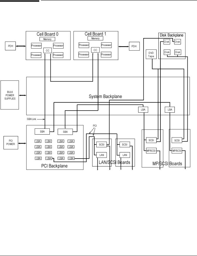
The hp rp7405/rp7410 is a 10U, 8-way SMP, rack-mount server that accommodates up to 32 GB of memory (64 GB available at a later date); PCI-4X I/O; and internal peripherals including disks and DVD/tape. Its high availability features include N+1 hot-pluggable fans and power, redundant power cords, and hot-pluggable PCI cards and internal disks. It uses the PA8700 PA-RISC processors.
Figure 1-1 hp rp7405/rp7410 Server (front view)
2 |
Chapter 1 |
Introduction
hp rp7405/rp7410 Overview
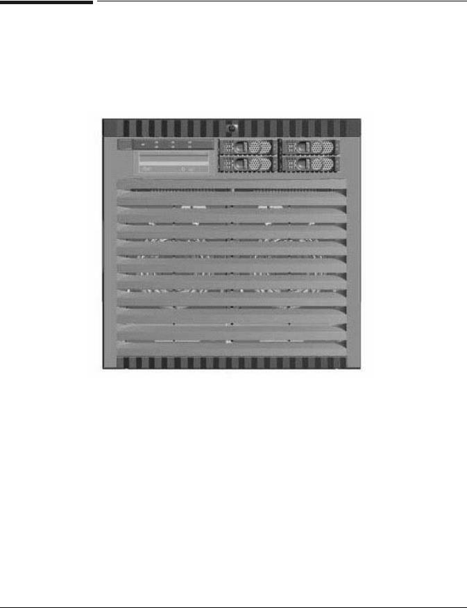
Figure 1-2 hp rp7405/rp7410 Server (without front bezel)
Improvements over its predecessor, N4000, include:
•Better availability and up time
•Depth optimized (shallower, fewer racking issues)
•Performance density increase
•Performance increase
•Internal removable media
•More internal disks
•Optimal power cord quantity (2 min., 4 max)
•Enabled for cell hot-plug, dual-partition, dual and/or redundant MP Core I/O
•More PCI slots (up to 16)
•Upgradeable to PCI-X
•Superset of MP Core I/O functionality
Cell Board
The cell board contains the processors, main memory, and the CC ASIC that interfaces the processors and memory to the off-board I/O. The CC provides a crossbar connection, which allows communication with other cell boards in the system. It connects to the PDH and SINC hardware. Each cell board holds up to 16 DIMMS. There can be one or two cell boards installed in a server. The cell boards have hot-plug capability.
Chapter 1 |
3 |

Introduction
hp rp7405/rp7410 Overview
System Backplane
The system backplane comprises the system clock generation logic, the system reset generation logic, DC-to-DC converters, power monitor logic, and two Local Bus adaptor (LBA) link-to-PCI converter ASICs. It also includes connectors for attaching the cell boards, PCI backplane, MP Core I/O MP/SCSI boards, SCSI cables, bulk power, chassis fans, front panel display, intrusion switches, and the system scan card. Unlike Superdome or the rp8400, there are no XBC chips on the system backplane. The “crossbar-less” back-to-back CC connection increases performance and reduces costs.
There are only two sets of cell board connectors, because the server has only two cells
Also, only half of the MP Core I/O board set connects to the system backplane. The MP/SCSI boards plug into the backplane, while the LAN/SCSI boards plug into the PCI Backplane.
I/O Subsystem
All of the I/O is integrated into the system by way of the PCI busses. The CC on each cell board communicates with one SBA over the SBA link. The SBA link consists of both an inbound and an outbound link with an effective bandwidth of approximately 1 GB/sec. The SBA converts the SBA link protocol into “ropes”. SBA can support up to 16 of these high-speed bi-directional links for a total aggregate bandwidth of approximately 4 GB/sec. The LBA acts as a bus bridge, supporting either one or two ropes, and capable of driving either
PCI-2x Turbo (33 MHz x 64 bits) or PCI-4 Twin Turbo (66 MHz x 64 bits) respectively.
4 |
Chapter 1 |

Introduction
hp rp7405 Servers
hp rp7405 Servers
Hewlett-Packard offers a cost-effective server based on the hp rp7410 by employing a reduced number of processors, memory, core I/O, or power supplies as indicated in Table 1-1.These servers provide a somewhat reduced performance than the fully functional hp rp7410 servers.
Table 1-1 |
hp rp7405 Servers |
|
|
|
|
|
|
Server |
|
Product Number |
Description |
|
|
|
|
rp7405 2-way system |
A7111A |
Includes rp7405 SMP base system, two 650-MHz PA-RISC |
|
|
|
|
processors, 4-GB memory (2 x 2GB memory modules), two |
|
|
|
73-GB 10k internal disks, one DVD drive, one cell board, one |
|
|
|
core I/O, and two power supplies |
|
|
|
|
rp7405 4-way system |
A7112A |
Includes rp7405 SMP base system, four 650-MHz PA-RISC |
|
|
|
|
processors, 8-GB memory (4 x 2 GB memory modules), four |
|
|
|
73-GB 10k internal disks, one DVD drive, two cell boards, |
|
|
|
two core I/O, and two powers supplies |
|
|
|
|
rp7405 8-way system |
A7113A |
Includes rp7405 SMP base system, eight 650-MHz PA-RISC |
|
|
|
|
processors, 16-GB memory (8 x 2 GB memory modules), four |
|
|
|
73-GB 10k internal disks, one DVD drive, two cell boards, |
|
|
|
two core I/O, and two power supplies |
|
|
|
|
These servers may be upgraded with additional processors/cell boards, memory, core I/O, etc. according to the corporate price list.
In addition, these servers may be upgraded to fully functional hp rp7410 servers with the kits given in Table 1-2.
Table 1-2 |
hp rp7405-to-rp7410 Upgrades |
|
|
|
|
|
|
|
Kit Description |
Upgrade |
Part Number |
|
|
|
|
Upgrade kit from 2-way rp7405 to rp7410 |
750 MHz upgrade |
A7144A |
|
|
|
|
|
|
|
875 MHz upgrade |
A7145A |
|
|
|
|
Upgrade kit from 4-way rp7405 to rp7410 |
750 MHz upgrade |
A7146A |
|
|
|
|
|
|
|
875 MHz upgrade |
A7147A |
|
|
|
|
Upgrade kit from 8-way rp7405 to rp7410 |
750 MHz upgrade |
A7148A |
|
|
|
|
|
|
|
875 MHz upgrade |
A7149A |
|
|
|
|
Chapter 1 |
5 |
Introduction
Detailed hp rp7405/rp7410 Description
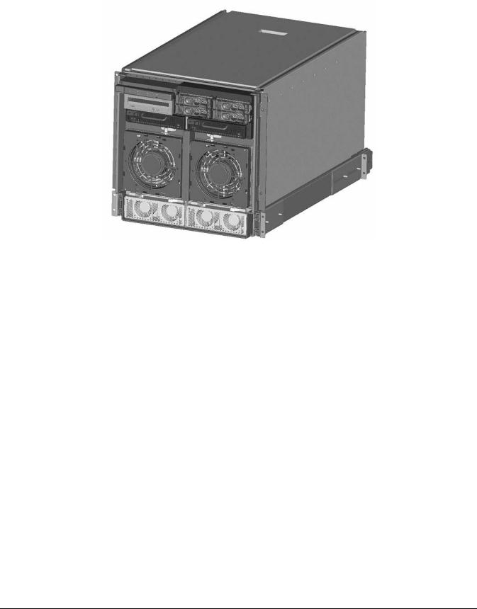
Detailed hp rp7405/rp7410 Description
Figure 1-3 hp rp7410 8-Way Block Diagram
6 |
Chapter 1 |
Introduction
Detailed hp rp7405/rp7410 Description
Cell Board
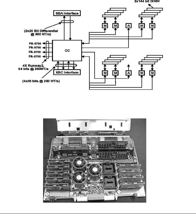
The cell board contains the processors, main memory, and the cell controller (CC) ASIC that interfaces the processors and memory to the off-board I/O. Shown in Figure 1-4 is the CC. This is the heart of the cell board. The CC provides a crossbar connection, which allows communication with other cell boards in the system. It connects to the PDH and SINC hardware. Each cell board holds up to 16 DIMMs. There can be one or two cell boards installed in an system. The cell boards have hot-plug capability.
Figure 1-4 |
Cell Controller |
Figure 1-5 |
Cell Board |
Chapter 1 |
7 |
Introduction
Detailed hp rp7405/rp7410 Description
The hp rp7405/rp7410 has a 48V distributed power system and receives the 48V power from the system backplane board. The cell board contains DC-to-DC converters to generate the required voltage rails. The DC-to-DC converters on the cell board do not provide N+1 redundancy.
The cell board contains several major buses including:
•Runway buses for each of the four processors
•Two memory buses (one going to each half of the main memory array)
•Incoming and outgoing I/O bus that goes off board to a SBA chip
•Incoming and outgoing crossbar bus that goes off board to the other cell boards
•PDH bus that goes to the PDH/SINC circuitry
All of these buses come together at the CC chip.
Due to space limitations on the cell board the PDH/SINC circuitry resides on a riser board that plugs at a right angle into the cell board. The cell board also includes clock circuits, test circuits and de-coupling capacitors.
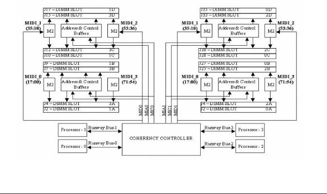
Figure 1-6 shows a simplified view of the memory subsystem. It consists of two independent access paths, each path having its own address bus, control bus, data bus, and DIMMs. In practice, the CC runs the two paths 180 degrees out of phase with respect to each other to facilitate pipelining in the CC. Address and control signals are fanned out through register ports to the SDRAMs on the DIMMs.
Data transferred between the CC and SDRAM passes through custom VLSI circuits (M2) that are bit-sliced; four form one 72-bit CC memory data bus. These circuits perform speed and width conversion between the SDRAM and MID busses. They also perform the write (tag update) portion of a read-modify-write (RMW) access. The CC memory data busses are bi-directional and run at 250 MT/s (million transfers per second). These links are self-clocked in that a pair of clock strobes is passed along with the data so that phase realignment can be done by the receiver.
Figure 1-6 Memory Subsystem
8 |
Chapter 1 |
Loading...