


 Loading...
HP BladeSystem Onboard Administrator
User Guide
Abstract
This guide provides information on the initial setup and operation of the HP Blade System Onboard Administrator. It also covers use of the Onboard Administrator GUI and enclosure Insight Display. The information in this guide applies to Version 4.20 (or later) of the HP Blade System Onboard Administrator.
Part Number: 695522-006
April 2014
Edition: 21
© Copyright 2006, 2014 Hewlett-Packard Development Company, L.P.
The information contained herein is subject to change without notice. The only warranties for HP products and services are set forth in the express warranty statements accompanying such products and services. Nothing herein should be construed as constituting an additional warranty. HP shall not be liable for technical or editorial errors or omissions contained herein.
Confidential computer software. Valid license from HP required for possession, use or copying. Consistent with FAR 12.211 and 12.212, Commercial Computer Software, Computer Software Documentation, and Technical Data for Commercial Items are licensed to the U.S. Government under vendor’s standard commercial license.
Microsoft®, Windows®, Windows Server®, Windows Vista®, and Windows XP® are U.S. registered trademarks of Microsoft Corporation. Google™ is a trademark of Google Inc. Java is a registered trademark of Oracle and/or its affiliates. Red Hat® is a registered trademark of Red Hat, Inc. in the United States and other countries. UNIX® is a registered trademark of The Open Group.

Contents |
|
Introduction.................................................................................................................................. |
8 |
Overview ................................................................................................................................................. |
8 |
Access requirements ................................................................................................................................ |
10 |
Onboard Administrator overview .............................................................................................................. |
11 |
Interfaces ............................................................................................................................................... |
12 |
Onboard Administrator authentication.............................................................................................. |
13 |
Running Onboard Administrator for the first time ......................................................................................... |
13 |
Signing in to the Onboard Administrator GUI ............................................................................................. |
15 |
Flash disaster recovery............................................................................................................................. |
17 |
Running the setup wizard ......................................................................................................................... |
18 |
Using online help .................................................................................................................................... |
19 |
Changing enclosure and device configurations ........................................................................................... |
19 |
Recovering the administrator password ...................................................................................................... |
19 |
Security considerations ............................................................................................................................ |
20 |
BladeSystem network architecture overview ...................................................................................... |
21 |
Recommended security best practices............................................................................................... |
21 |
Network ports ............................................................................................................................... |
22 |
Default FIPS Mode settings compared to strong encryption.................................................................. |
22 |
HP BladeSystem c7000 Enclosure hardware installation.................................................................. |
26 |
Installing Onboard Administrator modules .................................................................................................. |
26 |
HP BladeSystem Onboard Administrator cabling ......................................................................................... |
27 |
HP BladeSystem Insight Display .................................................................................................... |
29 |
HP BladeSystem c7000 2-inch Insight Display components ........................................................................... |
29 |
HP BladeSystem c3000 and c7000 3-inch Insight Display components .......................................................... |
30 |
Insight Display overview........................................................................................................................... |
30 |
Accessing the HP BladeSystem c3000 Insight Display .................................................................................. |
31 |
Running the Insight Display installation....................................................................................................... |
32 |
Navigating the Insight Display .................................................................................................................. |
37 |
Health Summary screen.................................................................................................................. |
39 |
Enclosure Settings screen................................................................................................................ |
39 |
Enclosure Info screen ..................................................................................................................... |
40 |
Blade and Port Info screen .............................................................................................................. |
41 |
Turn Enclosure UID On/Off screen................................................................................................... |
42 |
View User Note screen................................................................................................................... |
44 |
Chat Mode screen ......................................................................................................................... |
44 |
USB Menu screen .......................................................................................................................... |
45 |
KVM Menu screen ......................................................................................................................... |
46 |
Insight Display errors ............................................................................................................................... |
46 |
Power errors ................................................................................................................................. |
47 |
Cooling errors............................................................................................................................... |
47 |
Location errors .............................................................................................................................. |
47 |
Configuration errors....................................................................................................................... |
47 |
Device failure errors....................................................................................................................... |
48 |
Enclosure KVM ........................................................................................................................... |
49 |
Contents |
3 |
Features ................................................................................................................................................. |
49 |
First Time Setup Wizard .............................................................................................................. |
54 |
Before you begin..................................................................................................................................... |
54 |
User Preferences ..................................................................................................................................... |
55 |
FIPS....................................................................................................................................................... |
56 |
Enclosure Selection screen........................................................................................................................ |
57 |
Configuration Management screen ............................................................................................................ |
58 |
Rack and Enclosure Settings screen............................................................................................................ |
59 |
Administrator Account Setup screen........................................................................................................... |
61 |
Local User Accounts screen....................................................................................................................... |
62 |
Enclosure Bay IP Addressing ..................................................................................................................... |
63 |
Directory Groups Configuration screen ...................................................................................................... |
67 |
Directory Settings screen .......................................................................................................................... |
70 |
Onboard Administrator Network Settings screen ......................................................................................... |
72 |
Enclosure SNMP Settings screen................................................................................................................ |
77 |
Power Management screen ...................................................................................................................... |
78 |
Finish..................................................................................................................................................... |
81 |
Navigating Onboard Administrator .............................................................................................. |
82 |
Navigation overview ............................................................................................................................... |
82 |
Tree view ............................................................................................................................................... |
82 |
Graphical view navigation ....................................................................................................................... |
85 |
Rack View.................................................................................................................................. |
88 |
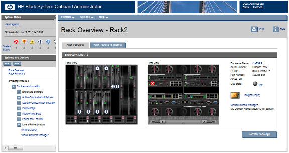
Rack Overview screen ............................................................................................................................. |
88 |
Topology modes ..................................................................................................................................... |
90 |
Rack Topology tab .................................................................................................................................. |
91 |
Rack Power and Thermal tab .................................................................................................................... |
92 |
Rack Firmware screen .............................................................................................................................. |
94 |
Configuring the HP BladeSystem c7000 enclosure and enclosure devices ......................................... |
96 |
Viewing the status screens ........................................................................................................................ |
96 |
Enclosure settings .................................................................................................................................... |
97 |
Selecting enclosures....................................................................................................................... |
97 |
Enclosure Settings screen................................................................................................................ |
97 |
AlertMail .................................................................................................................................... |
101 |
Device Power Sequence Device Bays tabs ...................................................................................... |
104 |
Date and Time ............................................................................................................................ |
106 |
Enclosure TCP/IP settings.............................................................................................................. |
108 |
Network Access .......................................................................................................................... |
114 |
Link Loss Failover......................................................................................................................... |
118 |
SNMP Settings ............................................................................................................................ |
119 |
Enclosure Bay IP Addressing ......................................................................................................... |
123 |
Device Summary ......................................................................................................................... |
133 |
Active to Standby ........................................................................................................................ |
135 |
DVD drive .................................................................................................................................. |
135 |
VLAN Configuration .................................................................................................................... |
149 |
Active Health System.................................................................................................................... |
156 |
HP Insight Remote Support ............................................................................................................ |
157 |
Enclosure Firmware Management .................................................................................................. |
167 |
Managing enclosures ............................................................................................................................ |
172 |
Powering off the enclosure............................................................................................................ |
172 |
Linking enclosures........................................................................................................................ |
172 |
Managing multiple enclosures ....................................................................................................... |
173 |
|
Contents 4 |
Active Onboard Administrator Module..................................................................................................... |
174 |
Active Onboard Administrator screen............................................................................................. |
174 |
Active Onboard Administrator Virtual Buttons tab ............................................................................ |
175 |
Active Onboard Administrator USB tab .......................................................................................... |
176 |
Active Onboard Administrator TCP/IP Settings screen ...................................................................... |
177 |
Certificate Administration Information tab ....................................................................................... |
179 |
Certificate Request tab ................................................................................................................. |
181 |
Certificate Upload tab.................................................................................................................. |
183 |
Firmware update ......................................................................................................................... |
184 |
Language Pack tab ...................................................................................................................... |
186 |
System log.................................................................................................................................. |
187 |
Standby Onboard Administrator Module.................................................................................................. |
192 |
Standby Onboard Administrator screen.......................................................................................... |
192 |
Standby Onboard Administrator Virtual Buttons tab ......................................................................... |
192 |
TCP/IP Settings for Standby OA .................................................................................................... |
193 |
Standby Onboard Administrator Certificate Administration Information tab ......................................... |
194 |
Standby Certificate Request tab..................................................................................................... |
195 |
Standby Certificate Upload tab ..................................................................................................... |
197 |
Device bays.......................................................................................................................................... |
198 |
Device Bay Overview screen......................................................................................................... |
198 |
Device Bay Status tab .................................................................................................................. |
200 |
Server Blade Information tab......................................................................................................... |
204 |
Server Blade Virtual Devices tab.................................................................................................... |
206 |
Boot Options tab ......................................................................................................................... |
208 |
IML Log tab................................................................................................................................. |
209 |
iLO screen .................................................................................................................................. |
210 |
Port Mapping.............................................................................................................................. |
212 |
Firmware.................................................................................................................................... |
224 |
Storage blades............................................................................................................................ |
233 |
I/O expansion blade information .................................................................................................. |
236 |
Interconnect bays .................................................................................................................................. |
238 |
Interconnect Bay Summary screen.................................................................................................. |
238 |
Interconnect Bay screen................................................................................................................ |
240 |
Interconnect Bay Information tab ................................................................................................... |
242 |
Interconnect Bay Virtual Buttons ..................................................................................................... |
243 |
Interconnect Bay Port Mapping screen............................................................................................ |
244 |
Enclosure power management ................................................................................................................ |
245 |
Power management planning........................................................................................................ |
245 |
Power and thermal screen ............................................................................................................ |
246 |
Power management ..................................................................................................................... |
247 |
Enclosure Power Meter screen....................................................................................................... |
252 |
Enclosure power allocation ........................................................................................................... |
256 |
Enclosure power summary ............................................................................................................ |
256 |
Power Subsystem screen............................................................................................................... |
257 |
Power Supply Information............................................................................................................. |
259 |
Fans and cooling management ............................................................................................................... |
260 |
Fan zones................................................................................................................................... |
260 |
Thermal subsystem....................................................................................................................... |
261 |
c7000 Enclosure fan location rules ................................................................................................ |
264 |
c3000 Enclosure fan location rules ................................................................................................ |
266 |
Managing users .................................................................................................................................... |
267 |
Users/Authentication ................................................................................................................... |
267 |
User roles and privilege levels....................................................................................................... |
267 |
|
Contents 5 |
Role-based user accounts.............................................................................................................. |
267 |
Local Users ................................................................................................................................. |
268 |
Directory Settings screen .............................................................................................................. |
273 |
Uploading a certificate................................................................................................................. |
276 |
Directory Certificate Upload tab .................................................................................................... |
277 |
Directory Test Settings tab............................................................................................................. |
277 |
Directory Groups......................................................................................................................... |
279 |
SSH Administration...................................................................................................................... |
286 |
HP SSO Integration...................................................................................................................... |
287 |
Two-Factor Authentication....................................................................................................................... |
288 |
Two-Factor Authentication Certificate Information tab ....................................................................... |
288 |
Two-Factor Authentication Certificate Upload tab............................................................................. |
289 |
Signed In Users..................................................................................................................................... |
289 |
Session Options tab..................................................................................................................... |
290 |
Insight Display ...................................................................................................................................... |
290 |
Virtual Connect Manager ....................................................................................................................... |
291 |
iLO Integration...................................................................................................................................... |
291 |
Management network IP dependencies .................................................................................................... |
292 |
Using the command line interface ............................................................................................... |
293 |
Command line overview......................................................................................................................... |
293 |
Setting up Onboard Administrator using the CLI ........................................................................................ |
293 |
Pinout signals for Onboard Administrator Serial RS232 connector ............................................................... |
295 |
Using the service port connection ............................................................................................................ |
295 |
Using configuration scripts...................................................................................................................... |
297 |
Configuration scripts .................................................................................................................... |
297 |
Reset factory defaults ................................................................................................................... |
298 |
HP Integrity i2 server blade support ............................................................................................ |
300 |
Updated support for HP Integrity BL860c i2, BL870c i2, and BL890c i2 Server Blades................................... |
300 |
Tree view and graphical view changes for HP Integrity i2 Server Blades....................................................... |
300 |
Port mapping changes for HP Integrity i2 Server Blades ............................................................................. |
302 |
Partner blade changes for HP Integrity i2 Server Blades ............................................................................. |
302 |
Troubleshooting ........................................................................................................................ |
303 |
Onboard Administrator error messages.................................................................................................... |
303 |
Onboard Administrator factory default settings.......................................................................................... |
318 |
Onboard Administrator SNMP traps ........................................................................................................ |
318 |
Known browser issues............................................................................................................................ |
319 |
Known network issues............................................................................................................................ |
320 |
Miscellaneous known issues.................................................................................................................... |
321 |
Enabling LDAP Directory Services Authentication to Microsoft Active Directory................................. |
323 |
Certificate Services................................................................................................................................ |
323 |
Preparing the directory........................................................................................................................... |
323 |
Uploading the DC Certificate (optional).................................................................................................... |
324 |
Creating directory groups....................................................................................................................... |
326 |
Testing the directory login solution........................................................................................................... |
328 |
Troubleshooting LDAP on Onboard Administrator ...................................................................................... |
329 |
Time zone settings .................................................................................................................... |
331 |
Universal time zone settings.................................................................................................................... |
331 |
Africa time zone settings ........................................................................................................................ |
331 |
Americas time zone settings.................................................................................................................... |
332 |
Asia time zone settings .......................................................................................................................... |
333 |
|
Contents 6 |
Oceanic time zone settings |
..................................................................................................................... 334 |
Europe time zone settings ....................................................................................................................... |
335 |
Polar time zone settings.......................................................................................................................... |
335 |
Support and other resources ...................................................................................................... |
337 |
Before you contact HP............................................................................................................................ |
337 |
HP contact information........................................................................................................................... |
337 |
Acronyms and abbreviations...................................................................................................... |
338 |
Documentation feedback ........................................................................................................... |
342 |
Index....................................................................................................................................... |
343 |
Contents 7

Introduction
Overview
HP BladeSystem Onboard Administrator is the enclosure management processor, subsystem, and firmware base that supports the HP BladeSystem c-Class enclosure and all the managed devices contained within the enclosure.
Onboard Administrator provides a single point from which to perform basic management tasks on server blades or switches within the enclosure. Onboard Administrator performs configuration steps for the enclosure, enables run-time management and configuration of the enclosure components, and informs you of problems within the enclosure through email, SNMP, or the Insight Display.
HP recommends that you read the specific HP BladeSystem c3000 or c7000 Enclosure user guide for enclosure specific information before proceeding with Onboard Administrator setup.
The HP BladeSystem Onboard Administrator provides several features designed to simplify management of c-Class blades and interconnects. The HP BladeSystem c3000 and c7000 Enclosures can be configured with redundant Onboard Administrator modules to provide uninterrupted manageability of the entire enclosure and blades in the event of a failure of a single Onboard Administrator module. The following table indicates which Onboard Administrator feature is enhanced when the enclosure contains redundant Onboard Administrator modules. For an enclosure with only a single Onboard Administrator module, the table indicates the behavior of the enclosure if the single Onboard Administrator module has failed or is removed. Enclosure Dynamic Power Capping, introduced in Onboard Administrator firmware version 2.31, is only available in HP BladeSystem enclosures with redundant Onboard Administrator modules installed.
Benefits of using a redundant Onboard Administrator versus a single Onboard Administrator
Onboard Administrator |
Single Onboard |
Single Onboard |
Redundant Onboard |
feature |
Administrator in enclosure |
Administrator failed or |
Administrator in enclosure |
|
|
removed |
|
|
|
|
|
Power allocation and control |
Yes. No enclosure dynamic |
No. Power supplies will |
Yes. Complete control |
for all blades and |
power capping as this |
continue to deliver power to |
including sustaining a failure |
interconnects |
requires redundant Onboard |
all blades and interconnects. |
of either Onboard |
|
Administrators. |
No power on requests can be |
Administrator. Enclosure |
|
|
made for blades or |
dynamic power capping |
|
|
interconnects. |
requires redundant Onboard |
|
|
|
Administrators. |
|
|
|
|
Cooling for all blades and |
Yes. Complete control. |
No. All enclosure fans will |
Yes. Complete control, |
interconnects. |
|
ramp to an un-managed |
including sustaining a failure |
|
|
higher speed to protect |
of either Onboard |
|
|
blades and interconnects from |
Administrator. |
|
|
overheating. |
|
Enclosure Bay IP Addressing |
Yes. Complete control. |
No. EBIPA IP addresses will |
Yes. Complete control, |
(EBIPA) |
|
be lost after lease timeout. |
including sustaining a failure |
|
|
|
of either Onboard |
|
|
|
Administrator. |
|
|
|
|
Ethernet communications to |
Yes. Complete control. |
No Ethernet management |
Yes. Complete control, |
Onboard Administrator, |
|
communications including |
including sustaining a failure |
|
|
internal management traffic |
of either Onboard |
|
|
|
Introduction 8 |

server iLO, interconnect |
|
such as Virtual Connect |
Administrator. |
management processors such |
|
Manager to other VC modules |
|
as Virtual Connect which use |
|
in the enclosure. |
|
the Onboard |
|
|
|
Administrator/iLO |
|
|
|
management port |
|
|
|
Information and health status |
Yes. Complete control. |
No information is available |
Yes. Complete control, |
reporting for all blades, |
|
from the Onboard |
including sustaining a failure |
interconnects, fans, power |
|
Administrator nor is any |
of either Onboard |
supplies, Onboard |
|
out-of-band information |
Administrator. |
Administrators, and enclosure |
|
available from VCM or iLO on |
|
through Onboard |
|
any server. |
|
Administrator's GUI or CLI, |
|
|
|
alert mail, or SNMP |
|
|
|
Insight Display |
Yes. Complete control. |
No. |
Yes. Complete control, |
|
|
|
including sustaining a failure |
|
|
|
of either Onboard |
|
|
|
Administrator. |
|
|
|
|
Enclosure DVD (requires |
Yes. Complete control. |
No. |
Yes. Complete control, |
either c3000 DVD option, |
|
|
including sustaining a failure |
external USB DVD drive, or |
|
|
of either Onboard |
USB key) |
|
|
Administrator. |
Enclosure KVM (requires |
Yes. Complete control. |
No. |
Yes. Complete control. For the |
c3000 KVM option or |
|
|
HP c3000 Enclosure, requires |
Onboard Administrator |
|
|
both c3000 KVM option and |
module with VGA connector) |
|
|
redundant Onboard |
|
|
|
Administrator option. For the |
|
|
|
HP c7000 Enclosure, requires |
|
|
|
two of the newer Onboard |
|
|
|
Administrator modules with |
|
|
|
VGA connector. |
|
|
|
|
Stored Onboard Administrator settings and module replacement |
|
||
Enclosure model |
Single Onboard |
Redundant Onboard |
Redundant Onboard |
|
Administrator in enclosure |
Administrator (same |
Administrator (different |
|
|
replacement type |
replacement type |
|
|
installed)1 |
installed)1 |
c3000 |
All enclosure settings are lost |
All enclosure settings are |
When changing from the |
|
when a single module is |
retained on the remaining |
non-redundant c3000 |
|
removed and must be restored |
module and those settings are |
Onboard Administrator to |
|
manually using Insight Display |
synchronized to the replaced |
redundant Onboard |
|
and USB key, GUI, or CLI. |
module if the firmware |
Administrator with DDR2, the |
|
|
versions match.2 |
enclosure settings must be |
|
|
|
restored manually using |
|
|
|
Insight Display and USB key, |
|
|
|
GUI, or CLI. |
|
|
|
|
c7000 |
All enclosure settings are lost |
All enclosure settings are |
All enclosure settings are |
|
when a single module is |
retained on the remaining |
retained on the remaining |
|
removed and must be restored |
module and those settings are |
module and those settings are |
|
manually using Insight Display |
synchronized to the replaced |
synchronized to the replaced |
|
and USB key, GUI, or CLI. |
module if the firmware |
module if the firmware |
|
|
versions match.2 |
versions match.2 |
|
|
|
|
1 Removing a redundant Onboard Administrator module immediately results in the remaining module becoming the Active Onboard Administrator.
Introduction 9
2 If redundant Onboard Administrator firmware versions do not match, the settings are not automatically synchronized. Synchronize the firmware by using the Insight Display, GUI, or CLI command, and then the settings are automatically synchronized to the replaced Onboard Administrator module.
Access requirements
To access HP BladeSystem Onboard Administrator web interface, you must have the Onboard Administrator IP address and a compatible web browser. You must access the application through HTTPS (HTTP packets exchanged over an SSL/TLS-encrypted session).
HP BladeSystem Onboard Administrator web interface requires an XSLT-enabled browser with support for JavaScript 1.3 or the equivalent.
For a list of browsers supported for use with Onboard Administrator, see the latest version of the Onboard Administrator release notes.
Before running the web browser, you must enable the following browser settings:
•ActiveX (for Microsoft® Internet Explorer)
•Cookies
•JavaScript
If you receive a notice that your browser does not have the required functionality, be sure that your browser settings meet the preceding requirements, and see "Recovering the administrator password (on page 19)."
If you use an installed language pack with the Onboard Administrator GUI and the browser does not display all characters correctly, make sure the operating system has the corresponding language support installed.
To access HP BladeSystem Onboard Administrator CLI, use HP BladeSystem Onboard Administrator IP address and a terminal or terminal application. To access the CLI interface, you must use Telnet or SSH, depending on which of these protocols are enabled.
The following ports are used to access and monitor the Onboard Administrator.
Protocol |
Incoming port |
Outgoing port |
|
|
|
SSH |
22 |
— |
Telnet |
23 |
— |
SMTP |
— |
25 |
Browser access |
80 |
80 |
Browser access encrypted |
443 |
443 |
SNMP get/set |
161 |
— |
SNMP traps |
— |
162 |
LDAP SSL |
— |
636 |
LDAP Global Catalog |
— |
3269 |
Terminal services pass-through from PC to iLO |
3389 |
— |
iLO Remote Console |
17790 |
— |
Virtual media from PC to iLO |
17988 |
— |
Remote syslog |
— |
514 |
You can change LDAP and Remote syslog port numbers.
If a protocol is disabled, then the corresponding ports are also disabled.
To use EDPC, iLO firmware 1.70 or later is required.
Introduction 10
NOTE: The Onboard Administrator supports multiple simultaneous login sessions, whether through the Onboard Administrator web interface or CLI, except for LDAP/Active Directory users where only one login session is allowed per user.
Onboard Administrator overview
Managing a c-Class enclosure involves multiple functions:
•Detecting component insertion and removal
•Identifying components including required connectivity
•Managing power and cooling
•Controlling components including remote control and remote consoles
Detecting component insertion and removal
Onboard Administrator provides component control in c-Class enclosures. Component management begins after the component is detected and identified. The Onboard Administrator detects components in BladeSystem c-Class enclosures through presence signals on each bay. When you insert a component into a bay, the Onboard Administrator immediately recognizes and identifies the component. When you remove a component from a bay, the Onboard Administrator deletes the information about that component.
Identifying components
To identify a component, Onboard Administrator reads a FRU EEPROM that contains specific factory information about the component such as product name, part number, and serial number. All FRU EEPROMs in c-Class enclosures are powered up, even if the component is turned off. Therefore, Onboard Administrator can identify the component before granting power. For devices such as fans, power supplies, and Insight Display, Onboard Administrator directly reads the FRU EEPROMs. Onboard Administrator accesses server blade FRU EEPROMs through iLO management processors.
•The server blades contain several FRU EEPROMs: one on the server board, which contains server information and embedded NIC information, and one on each installed mezzanine option cards.
•Server blade control options include auto login to the iLO web interface and remote server consoles, virtual power control, and boot order control. Server blade control options also include extensive server hardware information including BIOS and iLO firmware versions, server name, NIC and option card port IDs, and port mapping.
•Onboard Administrator provides easy-to-understand port mapping information for each server blade and interconnect module in the enclosure.
The NIC and mezzanine option FRU information informs Onboard Administrator of the type of interconnects each server requires. Before power is provided to a server blade, Onboard Administrator compares this information with the FRU EEPROMs on installed interconnect modules to check for electronic keying errors. For interconnect modules, Onboard Administrator provides virtual power control, dedicated serial consoles, and management Ethernet connections.
A 16-step progress meter appears when the Active Onboard Administrator boots. Some steps might take as much as several minutes, depending on the number and types of blades, mezzanine cards, and interconnects.
Managing power and cooling
The most important Onboard Administrator tasks are power control and thermal management. Onboard Administrator can remotely control the power state of all components in BladeSystem c-Class enclosures. For
Introduction 11
components in device bays in the front of each enclosure, Onboard Administrator communicates with iLO to control servers, and with a microcontroller to control options such as storage blades. A separate microcontroller controls power to the interconnect modules.
After components are powered, the Onboard Administrator begins thermal management with Thermal Logic. The Thermal Logic feature in BladeSystem c-Class minimizes power consumption by the enclosure fan subsystem by reading temperature sensors across the entire enclosure. Then, Thermal Logic changes fan speed in different zones in the enclosure to minimize power consumption and maximize cooling efficiency.
Controlling components
Onboard Administrator uses embedded management interfaces to provide detailed information and health status for all bays in the enclosure including presence detection signals in each bay, i2c, serial, USB, and Ethernet controllers. Onboard Administrator also offers information on firmware versions for most components in the enclosure and can be used to update those components.
Interfaces
Each c-Class enclosure has several external management interfaces that connect the user to Onboard Administrator. The RJ-45Ethernet jack is the primary interface. This interface provides network access to the Onboard Administrator and management interface on all server blades (iLO), storage blades (TBM), and interconnect modules.
A serial port on the Onboard Administrator module provides full out-of-band CLI access to the Onboard Administrator and is used for Onboard Administrator firmware flash recovery.
USB ports on Onboard Administrator are used to connect external DVD drives to support the enclosure DVD feature. In addition, you can order an optional internal DVD drive for the c3000 Enclosure. The USB port on the Onboard Administrator might have a sticker on the port, stating that it is reserved for future use. To use the USB port with Onboard Administrator firmware version 2.00 or later, remove the sticker.
All c-Class enclosures support two enclosure link connectors that provide private communications among enclosures linked with CAT5 cable. The enclosure link-up connector provides an enclosure service port that allows you to temporarily connect a laptop personal computer to any linked enclosure Onboard Administrator for local diagnostics and debugging.
The KVM Module option for the c3000 Enclosure plugs into the rear bay adjacent to interconnect module 1 and provides a VGA connector and two more USB connectors for the c3000 enclosure. This KVM module enables the enclosure KVM feature for the c3000 enclosure. The VGA connector attaches to an external VGA monitor and external USB keyboard and mouse to provide access to all the server video consoles or the Onboard Administrator CLI or Insight Display.
The new c7000 Onboard Administrator Module with KVM adds a VGA connector to the c7000 Onboard Administrator, enabling the Enclosure KVM feature for the c7000 Enclosure. The Active c7000 Onboard Administrator Module with KVM provides the same Enclosure KVM capabilities as the optional c3000 KVM Module. An external USB hub (not included) must be used to connect a USB DVD drive at the same time as the KVM USB for keyboard and mouse for simultaneous Enclosure KVM and Enclosure DVD functionality. The Standby Onboard Administrator Module with KVM will only provide access to the Onboard Administrator CLI login which enables the logged in user to force a takeover.
Each c-Class enclosure includes an embedded Insight Display on the front of the enclosure which provides status and information on all the bays in a c-Class enclosure and diagnostic information if the Onboard Administrator detects a problem in the enclosure. The Insight Display configures key settings in the Onboard Administrator including the IP address of the Onboard Administrator.
Introduction 12

Onboard Administrator authentication
Security is maintained for all Onboard Administrator user interfaces through user authentication. User accounts created in Onboard Administrator are assigned one of three privilege levels and granted access to component bays at the specified privilege level. Onboard Administrator stores the passwords for local user accounts and can be configured to use LDAP authentication for user group accounts. The Insight Display can be protected by an LCD PIN code or completely disabled. An LCD PIN code protects against unauthorized access to the Insight Display and Enclosure KVM. Use of the KVM Module to access server consoles is protected by server operating system user name and passwords.
IMPORTANT: Onboard Administrator does not support OpenLDAP.
Role-based user accounts
Onboard Administrator provides configurable user accounts that can provide complete isolation of multiple administrative roles such as server, LAN, and SAN. User accounts are configured with specific device bay or interconnect bay permissions and one of three privilege levels: administrator, operator, or user. An account with administrator privileges including Onboard Administrator bay permission can create or edit all user accounts on an enclosure. Operator privileges enable full information access and control of permitted bays. User privileges enable information access but no control capability.
Onboard Administrator requires you to log in to the web GUI or CLI with an account and password. The account can be a local account where the password is stored on Onboard Administrator or an LDAP account, where Onboard Administrator contacts the defined LDAP server to verify the user credentials. Two-factor authentication enables even tighter security for the user management session to Onboard Administrator.
Rather than requiring separate logins to multiple resources (once to each enclosure, once to every server management processor, or both), Onboard Administrator enables single point access for linked enclosures in a rack. In this way, the administrator can use single sign-on to log in to a single Onboard Administrator and use the web GUI to graphically view and manage the HP BladeSystem c-Class components in up to seven linked enclosures. (The single sign-on requires that all the enclosure active Onboard Administrators have the same password.) For example, an IT administrator can automatically propagate management commands, such as changing the enclosure power mode, across all the linked enclosures. A valid account must be present on each linked enclosure to gain access. For more information, see "Signing in to the Onboard Administrator GUI (on page 15)."
Login security
Onboard Administrator provides several login security features. No penalty is imposed after an initial failed login attempt. With all subsequent failed attempts, Onboard Administrator imposes a 10-second to 20-second delay. An information page appears during each delay. This action continues until a valid login is completed. This feature assists in defending against possible dictionary attacks.
Onboard Administrator saves a detailed log entry for all failed login attempts.
Running Onboard Administrator for the first time
Setting up a c-Class enclosure using the Onboard Administrator is simplified by using the Insight Display first time installation wizard, followed by use of the Onboard Administrator GUI First Time Wizard or Onboard Administrator CLI to complete the reset of the enclosure settings.
Introduction 13

When operating in FIPS Mode, configure FIPS Mode before performing any other enclosure or Onboard Administrator configuration, including configuration of the Virtual Connect or First Time Setup Wizard. Enabling FIPS Mode on an Onboard Administrator module or redundant pair of modules forces the Onboard Administrator modules to be reset to factory defaults. After configuring FIPS Mode, perform the configuration steps in this section. For more information on FIPS Mode, see "FIPS tab (on page 117)."
The Onboard Administrator modules, server blade iLO management processors and many interconnect modules default to DHCP for their management IP address. If the user has DHCP and connects the Onboard Administrator management port to the DHCP server, then the Onboard Administrator modules, all iLO, and interconnect modules supporting and configured to use the Onboard Administrator internal management network will all automatically obtain DHCP addresses from the user DHCP server.
If you do not have a DHCP server for assigning IP addresses to management processors, you must configure each Onboard Administrator IP address and then all the individual device and interconnect module management IP addresses by using one of the following methods:
•Recommended Practice - configure each Onboard Administrator with a static IP address using the Insight Display. Then log in to the Onboard Administrator GUI and use the First Time Setup Wizard or log in to the Onboard Administrator CLI and configure and enable Enclosure Bay IP Addresses (EBIPA) for Device Bays and Interconnect Bays. Enabling EBIPA for a bay will allow that server or interconnect module to be replaced and the new module will automatically obtain the previously configured IP address for that bay.
•Alternatively configure each device and interconnect module for static IP manually. For ProLiant server blades, you must connect to each server blade from SUV port (using the SUV cable included with each enclosure) and configure the iLO IP address manually during POST by pressing F8 to access the iLO Option ROM settings. For the interconnect modules with management processors that can use the Onboard Administrator management network, access and configure their IP address using either an external serial console port or the Onboard Administrator CLI serial connection to that bay. After changing the interconnect module IP address manually, the switch may require power cycling to use the new setting.
IMPORTANT: Do not configure the IP address for any Onboard Administrator in the 169.254.x.x range.
The initial credentials to log in to a new Onboard Administrator module are printed on a label on each module. The user is Administrator and the password is unique to each module. This password must be captured by the installer and communicated to the remote Administrator for the first remote login to the Onboard Administrator GUI or Onboard Administrator CLI.
The enclosure settings can be configured manually or uploaded from a configuration script or file. The web GUI offers a First Time Setup Wizard. The CLI can be accessed from the Onboard Administrator serial port, Ethernet management port, service port, or by using the Enclosure KVM - Onboard Administrator CLI button.
An alternative to manual configuration is to upload an enclosure configuration file to the active Onboard Administrator using either the GUI or CLI with an HTTP, FTP or TFTP network location for the configuration file, or use the GUI, CLI or Insight Display to upload a configuration file from a USB key drive plugged into the active Onboard Administrator USB port.
The recommended practice to create an enclosure configuration file is to use the GUI, CLI, or Insight Display USB Key Menu to save the existing configuration to a file. The saved configuration file is a set of CLI text commands for each configuration item. The Onboard Administrator will not save user passwords when it saves a configuration file. The user can edit the configuration file and insert the password commands for
Introduction 14
each user account - or use the Administrator local account to individually update all user passwords after restoring a previously saved enclosure configuration file.
If the enclosure contains redundant Onboard Administrator modules, the remaining Onboard Administrator updates the new Onboard Administrator with all the settings.
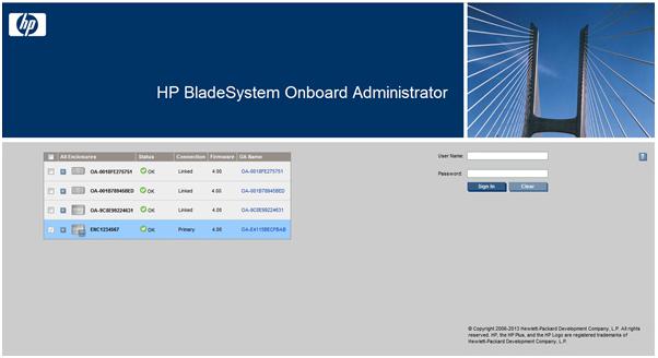
Signing in to the Onboard Administrator GUI
Enter the user name and initial administration password for your Onboard Administrator. The default account credentials can be found on the tag attached to the Onboard Administrator.
When signing in to the Onboard Administrator, the following issues might occur:
•You are not entering the information correctly. Passwords are case sensitive.
•The account information you are entering has not been set up for HP BladeSystem Onboard Administrator.
•The user name you are entering has been deleted, disabled, or locked out.
•The password for the account must be changed.
•You are attempting to sign in from an IP address that is not valid for the specified account.
•The password for the Administrator account has been forgotten or lost. To reset the Administrator password, see "Recovering the Administrator password (on page 19)."
If you continue to have issues signing in, contact your administrator.
If you have the same credentials on multiple enclosures, you can use single sign-on to log in to multiple linked enclosures. Before signing in, select the box next to each of the linked enclosures listed in the table on the Sign-in page, as shown in the following table. In this scenario, you are attempting to log in to three active Onboard Administrators on the corresponding selected enclosures, using the supplied user name and password. Alternatively, to verify and log in to all the linked enclosures, select the box at the top of the check box column. If the login succeeds, then each of those enclosures is viewed in the same GUI window. The display order of each enclosure is based on the enclosure link cables. Connect the "down-link" port of the
Introduction 15
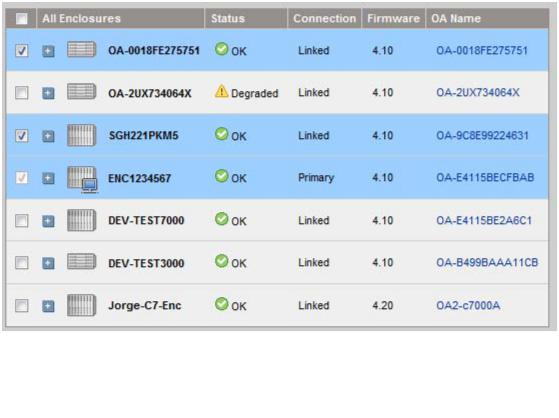
topmost enclosure to the "up-link" port of the following enclosure. Repeat until the bottom enclosure is reached. This GUI order is the same order that appears in the SHOW TOPOLOGY command.
As shown in the preceding example, the enclosure table on the Sign-in page also provides information on the enclosure status, connection, firmware version, OA name, and rack position. If extended data has been enabled on the Network Access (on page 114) page Anonymous Data tab, you can view more detailed
enclosure and Onboard Administrator information by selecting the 
 sign to the left of the enclosure icon.
The 
 sign appears only if extended data is enabled on that enclosure. Through Location Discovery Services, the extended data includes location information for each chassis. For more information about Location Discovery Services, see "Rack Overview screen (on page 88)." Extended data is enabled by default. If extended data is disabled on an enclosure, the enclosure status appears as N/A.
Introduction 16
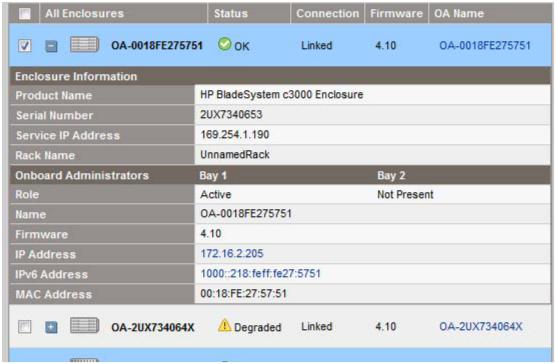
The following figure shows the extended data for the first enclosure listed in the table.
Flash disaster recovery
To successfully recover an Onboard Administrator from a failed flash, you must have the following:
•Local access to the enclosure
•A DHCP server accessible by the Onboard Administrator
•A TFTP server accessible by the Onboard Administrator
•Onboard Administrator firmware (.bin file)
To recover from a failed flash use one of the following processes:
•If you have only one Onboard Administrator in the enclosure or you want to Flash Recover the Active OA:
a.With a null-modem cable (9600 N, 8, 1, VT100), locally connect to the Onboard Administrator.
b.Press and hold the Reset button of the Onboard Administrator for 5 seconds.
c.On the serial console, when you are prompted for Flash Recovery or Reset Password, press F. The Onboard Administrator obtains an IP address through DHCP.
d.At the prompt for the TFTP server IP address (where the Onboard Administrator image files are stored), enter the appropriate IP address.
e.You are prompted for the path to the Onboard Administrator firmware image. The Onboard Administrator downloads the image and flashes itself.
Upon successful completion of this process, the Onboard Administrator firmware is up to date, and any error condition is repaired.
•If you have two Onboard Administrator modules in the enclosure and you want to Flash Recover the Active OA:
Introduction 17
a.With a null-modem cable (9600 N, 8, 1, VT100), locally connect to the Onboard Administrator.
b.Press and hold the Reset button of the Onboard Administrator for 5 seconds.
c.On the serial console, when you are prompted for Flash Recovery or Reset Password, do not type anything. Wait at least 2 minutes or more to let the Standby OA to become the Active OA before proceeding to the next step.
d.When the OA to be flashed has become the Standby OA, press and hold the Reset button a second time on the same OA as in step b.
e.On the serial console, when you are prompted for Flash Recovery or Reset Password, press F. The Onboard Administrator obtains an IP address through DHCP.
f.At the prompt for the TFTP server IP address (where the Onboard Administrator image files are stored), enter the appropriate IP address.
g.You are prompted for the path to the Onboard Administrator firmware image. The Onboard Administrator downloads the image and flashes itself.
Upon successful completion of this process, the Onboard Administrator firmware is up to date, and any error condition is repaired.
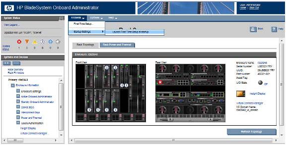
Running the setup wizard
To run the setup wizard, sign in to Onboard Administrator. The First Time Setup Wizard starts automatically when you sign in to Onboard Administrator for the first time. This wizard assists you in setting up all of the functions of the Onboard Administrator. You can access the setup wizard at any time after initial setup by clicking the Wizards link on the top left of the center screen.
For detailed information, see "First Time Setup wizard (on page 54)."
Introduction 18
Using online help
To access online help, click the blue box with the white question mark or Help located on the top right of the screen under the header bar. Online help displays information related to the section of Onboard Administrator in which you are navigating.
Changing enclosure and device configurations
After you have completed the First Time Setup Wizard, you can return to the Onboard Administrator GUI to make configuration changes at any time. For information that will help you make changes to enclosure and device configuration, user setup, and LDAP server settings and LDAP groups, see "Configuring the HP BladeSystem c7000 enclosure and enclosure devices (on page 96)."
For information about enclosure power settings, see "Enclosure Power Management (on page 245)."
Recovering the administrator password
If the Administrator password has been lost, you can reset the administrator password to the factory default that shipped on the tag with the Onboard Administrator module. The Onboard Administrator resets a lost password to Lost Password/Flash Disaster Recovery (LP/FDR) mode. To reset the administrator password to the factory default:
1.Connect a computer to the serial port of the Active Onboard Administrator using a null-modem cable.
2.With a null-modem cable (9600 N, 8, 1, VT100) locally connect to the Onboard Administrator.
3.Open a suitable terminal window utility (Windows or Linux), and connect to the Active Onboard Administrator.
4.Press and hold in the Onboard Administrator reset button for 5 seconds.
5.To boot the system into Lost Password modem Press L. The password appears as the system reboots.
Introduction 19

Alternatively, to reset a password on the Onboard Administrator, select the Insight Display (LCD panel) USB Menu option. This option restores a configuration script using command line interface commands stored on a USB key.
NOTE: If the Insight Display USB menu buttons are locked, then the serial port method must be used. If the LCD panel is locked, then a large “lock” symbol appears on the screen.
In this example, the OA Administrator password is set to Password123.
1.Create a text file named reset_password.cfg with the one line command: SET USER PASSWORD “Administrator” “Password123”
2.Insert the flash drive with reset_password.cfg file into the USB port of the active Onboard Administrator. The LED on the Onboard Administrator indicates which OA is active.
3.Using the Onboard Administrator Insight Display, navigate to the main menu, select USB Key Menu, and then click OK.
4.If Insight Display PIN Protection is enabled, you are prompted to enter the PIN. Select Accept, and then click OK.
5.Select Restore Configuration, then click OK. The USB flash drive in the Onboard Administrator is scanned and the available .cfg files are listed.
6.Select the reset_password.cfg file, and then click OK.
7.The Confirm Operation screen appears, click OK.
8.Login into the Onboard Administrator with the user ID and password specified in step 1.
Security considerations
This section documents the architecture and best practice security recommendations to be considered when configuring the Onboard Administrator and compares default settings with the previous versions.
Introduction 20
BladeSystem network architecture overview
All device bays, interconnect modules, and Onboard Administrator modules are connected to an internal enclosure network that is managed by the active Onboard Administrator. Network traffic from business applications running on server blades is routed through interconnect switch modules and onto the production network.
Although it is possible for the management and production networks to be connected, the management network should be isolated from production traffic and the intranet. From a security perspective, this reduces access and ability to attack the management interfaces. From an efficiency standpoint, separate networks keep production traffic off the management network.
Recommended security best practices
In addition to the best practices, note these additional considerations.
Physical presence considerations
Physical access to a system often implies administrator privilege. The Onboard Administrator is no exception. For more information on how to configure the Onboard Administrator administrator, see "Configuring the HP BladeSystem c7000 enclosure and enclosure devices (on page 96)."
•Verifying physical cabling
The BladeSystem enclosure can have many cables attached to the enclosure. Cables connected to the interconnect switch modules are generally for production network traffic. All other cables and ports are generally for enclosure management network traffic and should be carefully inspected.
o Ensure that enclosure link ports are connected only to enclosure link ports on other enclosures. o Inspect Onboard Administrator serial ports for unauthorized connections.
o Inspect Onboard Administrator USB ports for unauthorized connections.
Introduction 21
•Securing the Insight Display LCD panel
The Insight Display LCD panel allows for configuration and monitoring of key Onboard Administrator settings: network address configuration and power up/down of server blade bays to name a few critical BladeSystem functions. HP recommends securing the Insight Display LCD panel with a PIN, particularly in a multi-tenant datacenter. Furthermore, certain regulatory or industry standards, such as PCI, might require that all interfaces be secured with a PIN/password, regardless of requiring physical access.
The Insight Display LCD panel buttons are locked by default in FIPS Mode ON/DEBUG. For more information, see "FIPS tab (on page 117)."
Set factory defaults before hardware redeployment
The very nature of redundant hardware is to ensure that all settings are present so that if a failure occurs on the Active Onboard Administrator, the Standby Onboard Administrator can take over the active role. This means that local user account information is duplicated on the Standby Onboard Administrator. If Enclosure IP mode is configured, then the private key used for SSL communications is also stored on the Standby Onboard Administrator. (Enclosure IP mode is not configured by default.) Depending on the security requirements for the datacenter, critical security parameters should be cleared from the hardware before decommissioning or reprovisioning an enclosure or components inside the enclosure, such as the Onboard Administrator, VC, and iLO for HP BladeSystem.
To ensure all critical security parameters are cleared, SET FACTORY defaults. Additionally, the Administrator password can be set to factory “toe-tag” value by manually changing the password or connecting a serial cable and invoking the lost password recovery procedure. For instructions, see "Recovering the administrator password (on page 19)."
Isolate the management network
No matter how secure a device might appear to be, there will always be some sort of new attack or vulnerability. As a preventative measure and to follow industry best practices, HP strongly recommends that the management network be separate from the production network. Furthermore, do not place the management network on the open internet or firewall DMZ without requiring additional access authentication, such as using a VPN/tunnel.
Network ports
For more information on ports, see "Access requirements (on page 10)."
For more information on managing HP software through a firewall, see the Managing HP Servers Through Firewalls with Insight Management White Paper. This document may be downloaded from the HP Insight Management Information Library (http://www.hp.com/go/docs).
Default FIPS Mode settings compared to strong encryption
Beginning with version 3.70, Onboard Administrator significantly upgrades the Onboard Administrator cryptographic capabilities by adding a new FIPS Mode of operation. FIPS Mode enforces a number of requirements that differ significantly from the Enforce Strong Encryption setting in Onboard Administrator version 3.60 and prior releases. As of version 3.70, the default security settings in Onboard Administrator have been upgraded and are now equivalent to the version 3.60 Enforce Strong Encryption setting. The security improvements remove weak algorithms for message authentication, default the SSL hash signature algorithm to SHA-256, and support use of only FIPS 140-2 approved ciphers. For more information, see the following table. A list of supported SSH ciphers, SSH key exchange algorithms, and SSH Message Authentication Code algorithms follows the table.
Introduction 22

NOTE: When running a version of Onboard Administrator firmware earlier than version 3.70 with Strong Encryption mode enabled, if you update the firmware to version 3.70 or later, an entry might be logged to the Onboard Administrator syslog indicating that the Onboard Administrator is operating in FIPS Mode. This syslog entry ("FIPS: OA is operating in FIPS Mode On") is incorrect and can be ignored.
FIPS Mode and Encryption settings
|
OA 3.60 |
OA 3.60 |
OA 3.70 |
OA 3.70 |
OA 4.11 |
OA 4.11 |
|
|
Encryption |
Encryption |
FIPS |
FIPS Mode |
OA 4.20 |
OA 4.20 |
|
|
Normal |
Strong |
Mode |
ON |
FIPS Mode |
FIPS Mode |
|
|
|
|
OFF |
|
ON |
OFF |
|
|
|
|
|
|
|
|
|
General Security Items |
|
|
|
|
|
|
|
|
|
|
|
|
|
|
|
CSPs Zeroization |
NO |
NO |
NO |
YES |
YES |
NO |
|
Known Answer Tests |
NO |
NO |
NO |
YES |
YES |
NO |
|
(KATs) |
|
|
|
|
|
|
|
Power-up tests |
NO |
NO |
NO |
YES |
YES |
YES |
|
Continuous PRNG testing |
NO |
NO |
NO |
YES |
YES |
YES |
|
Minimum Password |
3 |
3 |
3 |
8 |
8 |
3 |
|
Length required |
|
|
|
|
|
|
|
Require Password |
NO |
NO |
NO |
YES |
YES |
NO |
|
Complexity (upper, lower, |
|
|
|
|
|
|
|
symbols) |
|
|
|
|
|
|
|
FIPS compatible PRNG |
NO |
NO |
YES |
YES |
YES |
YES |
|
(X9.31) |
|
|
|
|
|
|
|
Telnet service disabled |
NO |
NO |
NO1 |
YES |
YES |
NO1 |
|
Enclosure IP Mode |
NO |
NO |
NO |
YES |
YES |
NO |
|
disabled |
|
|
|
|
|
|
|
Support Dump disabled |
NO |
NO |
NO |
YES |
YES |
NO |
|
SNMPv1 and SNMPv2 |
NO |
NO |
NO |
YES |
YES |
NO |
|
services disabled |
|
|
|
|
|
|
|
Partition Integrity |
NO |
NO |
YES |
YES |
YES |
YES |
|
Checking |
|
|
|
|
|
|
|
Requires Insight Display |
NO |
NO |
NO |
YES |
YES |
NO |
|
LCD PIN |
|
|
|
|
|
|
|
SSL Encryption |
|
|
|
|
|
|
|
|
|
|
|
|
|
|
|
Default SSL Key Size |
2048 |
2048 |
2048 |
2048 |
2048 |
2048 |
|
Default self-signed |
SHA1 |
SHA1 |
SHA256 |
SHA256 |
SHA256 |
SHA256 |
|
certificate Hash Signature |
|
|
|
|
|
|
|
algorithm |
|
|
|
|
|
|
|
Configurable SSL hash |
NO |
NO |
YES |
YES |
YES |
YES |
|
signature algorithms on |
|
|
|
|
|
|
|
self signed certificate |
|
|
|
|
|
|
|
SSL Protocols |
SSLv3 |
SSLv3 |
SSLv3 |
TLSv1 |
TLSv1 |
SSLv3 |
|
|
TLSv1 |
TLSv1 |
TLSv1 |
|
TLSv1.1 |
TLSv1 |
|
|
|
|
|
|
TLSv1.2 |
TLSv1.1 |
|
|
|
|
|
|
|
TLSv1.2 |
|
|
|
|
|
|
|
|
|
Reject Certificates with |
NO |
NO |
NO |
YES |
YES |
NO |
|
non FIPS Hash Signature |
|
|
|
|
|
|
|
Algorithms2 |
|
|
|
|
|
|
|
|
|
|
|
|
|
Introduction 23 |
|
|
OA 3.60 |
OA 3.60 |
OA 3.70 |
OA 3.70 |
OA 4.11 |
OA 4.11 |
|
Encryption |
Encryption |
FIPS |
FIPS Mode |
OA 4.20 |
OA 4.20 |
|
Normal |
Strong |
Mode |
ON |
FIPS Mode |
FIPS Mode |
|
|
|
OFF |
|
ON |
OFF |
|
|
|
|
|
|
|
Permitted Certificate |
md5, sha1, |
md5, sha1, |
md5, |
sha1, |
sha1, |
sha1, |
Signature Hash |
sha224, |
sha224, |
sha1, |
sha224, |
sha224, |
sha224, |
Algorithms |
sha256, |
sha256, |
sha224, |
sha256, |
sha256, |
sha256, |
|
sha384, |
sha384, |
sha256, |
sha384, |
sha384, |
sha384, |
|
sha512 |
sha512 |
sha384, |
sha512 |
sha512 |
sha512 |
|
|
|
sha512 |
|
|
|
DES |
NO |
NO |
NO |
NO |
NO |
NO |
CAST5 |
NO |
NO |
NO |
NO |
NO |
NO |
Blowfish |
NO |
NO |
NO |
NO |
NO |
NO |
ARC4 |
YES |
YES |
NO |
NO |
NO |
NO |
3DES |
YES |
YES |
YES |
YES |
YES |
YES |
AES |
YES |
YES |
YES |
YES |
YES |
YES |
256 bits |
YES |
YES |
YES |
YES |
YES |
YES |
DHE-RSA-AES256-SHA |
|
|
|
|
|
|
256 bits AES256-SHA |
YES |
YES |
YES |
YES |
YES |
YES |
128 bits |
YES |
YES |
YES |
YES |
YES |
YES |
DHE-RSA-AES128-SHA |
|
|
|
|
|
|
128 bits AES128-SHA |
YES |
YES |
YES |
YES |
YES |
YES |
168 bits |
YES |
YES |
YES |
YES |
YES |
YES |
EDH-RSA-DES-CBC3-SHA |
|
|
|
|
|
|
168 bits DES-CBC3-SHA |
YES |
YES |
YES |
YES |
YES |
YES |
SSH Interface |
|
|
|
|
|
|
|
|
|
|
|
|
|
Default SSH key type and |
DSA 2048 |
DSA 2048 |
DSA 2048 |
DSA 1024 |
RSA 2048 |
RSA 2048 |
size |
|
|
|
|
|
|
HMAC-MD5 |
YES |
NO |
NO |
NO |
NO |
NO |
HMAC-SHA1-96 |
YES |
NO |
NO |
NO |
NO |
NO |
HMAC-SHA1 |
YES |
YES |
YES |
YES |
YES |
YES |
|
|
|
|
|
|
|
HMAC-SHA256 |
NO |
NO |
NO |
NO |
YES |
YES |
HMAC-SHA512 |
NO |
NO |
NO |
NO |
YES |
YES |
Insight Display KVM |
|
|
|
|
|
|
|
|
|
|
|
|
|
RC4 Encryption |
YES |
YES |
YES |
NO |
NO |
YES |
AES Support for LCD KVM |
NO |
NO |
YES |
YES |
YES |
YES |
1Telnet is disabled by default in Onboard Administrator 3.70 and later. When in FIPS Mode, Telnet cannot be enabled. 2Default certificate hash algorithm changed from SHA1 to SHA256 in Onboard Administrator 3.70. You can select different key sizes and hash algorithms with the GENERATE KEYS command.
SSH ciphers
The supported SSH ciphers are the same for FIPS Mode ON and FIPS Mode OFF, and for Onboard Administrator 3.71, 4.01, 4.11, and 4.20:
•aes128-ctr
•aes192-ctr
•aes256-ctr
Introduction 24
•aes128-cbc
•3des-cbc
•aes192-cbc
•aes256-cbc
•rijndael-cbc@lysator.liu.se
SSH key exchange algorithms
•OA 4.11 and OA 4.20
diffie-hellman-group-exchange-sha1,diffie-hellman-group14-sha1,diffie-he llman-group1-sha1
•OA 4.01 diffie-hellman-group-exchange-sha1,diffie-hellman-group14-sha1
•OA 3.71
diffie-hellman-group-exchange-sha1,diffie-hellman-group14-sha1,diffie-he llman-group1-sha1
o OA 4.01 and later versions include an option to enable/disable diffie-hellman-group1-sha1.
o OA 4.01 default for diffie-hellman-group1-sha1 is disabled.
o OA 4.11 and OA 4.20 default for diffie-hellman-group1-sha1 is enabled when FIPS Mode is OFF and disabled when FIPS Mode is ON.
SSH Message Authentication Code algorithms
The supported SSH Message Authentication Code is the same for FIPS Mode ON and FIPS Mode OFF. Onboard Administrator 3.70 and later no longer supports HMAC-MD5 and HMAC-SHA-96 for SSH2 message authentication.
•OA 4.11 and OA 4.20 hmac-sha2-256 hmac-sha2-512 hmac-sha1
•OA 4.01 hmac-sha1
•OA 3.71 hmac-sha1
Introduction 25
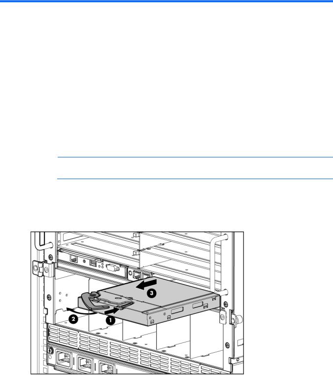
HP BladeSystem c7000 Enclosure hardware installation
Installing Onboard Administrator modules
The HP BladeSystem c7000 Enclosure is shipped with one HP BladeSystem Onboard Administrator module installed and can support up to two Onboard Administrator modules. Install Onboard Administrator modules based on the total number ordered:
•One Onboard Administrator module: Bay 1
•Two Onboard Administrator modules: Bays 1 and 2
Install an Onboard Administrator blank in an unused Onboard Administrator bay.
NOTE: When two Onboard Administrator modules are installed, the module installed in Bay 1 is active and the module installed in Bay 2 is redundant.
To install an Onboard Administrator module:
1.Remove the Onboard Administrator blank, if present.
a.Press the button on the front of the blank to release the handle.
b.Pull the handle, and slide the Onboard Administrator blank out of the Onboard Administrator tray.
HP BladeSystem c7000 Enclosure hardware installation 26

2.Slide the Onboard Administrator module into the Onboard Administrator tray, and close the handle. When the Onboard Administrator module is fully inserted, it locks into place.
HP BladeSystem Onboard Administrator cabling
Item |
Connector |
Description |
|
|
|
|
|
1 |
Enclosure |
Connects to the enclosure link-up port on the enclosure beneath it using a CAT5 patch |
|
|
link-down port |
cable. |
|
2 |
Enclosure link-up |
Connects to the enclosure link-down port on the enclosure above it using CAT5 patch |
|
|
port and service |
cable. On a stand-alone enclosure or the top enclosure in a series of linked |
|
|
port |
enclosures, the top enclosure link-up port may function as a service port. |
|
|
|
|
|
3 |
OA1/iLO |
Onboard Administrator Ethernet connection. Use a CAT5 patch cable to connect to |
|
|
|
the management network. Connect to this port to remotely communicate with the |
|
|
|
Onboard Administrator, all iLO ports on each server blade, and supporting |
|
|
|
interconnect module management parts. |
|
|
|
|
|
|
|
HP BladeSystem c7000 Enclosure hardware installation 27 |
|
Item |
Connector |
Description |
|
|
|
4 |
OA2/iLO |
Reserved for future Onboard Administrator connections. |
If the Onboard Administrator management Ethernet port is connected to a management LAN that also connects to server ports, be sure that the server applications do not overload the Onboard Administrator management port with broadcast packets. The Onboard Administrator management port forwards all broadcast packets from the management network to all the devices inside the enclosure, and the Onboard Administrator records network packet flooding messages to the active Onboard Administrator syslog when it detects a high rate of packets. If the server connections are 1GB, and the Onboard Administrator connection is 100 MB, the server broadcast packets can easily overwhelm the port on the network switch connected to the Onboard Administrator. If the network packet flooding persists, the Onboard Administrator performance is impacted with a possibility of Onboard Administrator restart if the packet flooding overwhelms the Onboard Administrator capacity. This condition occurs is because Onboard Administrator must inspect all packets from the network it is connected to so the Onboard Administrator can act as the management conduit for internal enclosure devices, such as iLOs or Virtual Connect management interfaces. While an Onboard Administrator restart does not cause direct customer traffic outage, this action can cause unnecessary inconvenience, especially in configurations with Virtual Connect.
If the Onboard Administrator is connected to a network with a DHCP server when you power up the enclosure, the Onboard Administrator and each iLO (one for each server blade) consumes a DHCP lease.
HP BladeSystem c7000 Enclosure hardware installation 28
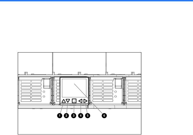
HP BladeSystem Insight Display
HP BladeSystem c7000 2-inch Insight Display components
Item |
Description |
Function |
|
|
|
1 |
Up arrow button |
Moves the menu selection up one position |
2 |
Down arrow button |
Moves the menu selection down one position |
3 |
OK button |
Accepts the highlighted selection and navigates to the selected |
|
|
menu |
4 |
Left arrow button |
Moves the menu or navigation bar selection left one position |
5 |
Right arrow button |
Moves the menu or navigation bar selection right one position |
6 |
Insight Display screen |
Displays Main Menu error messages and instructions |
|
|
|
HP BladeSystem Insight Display 29
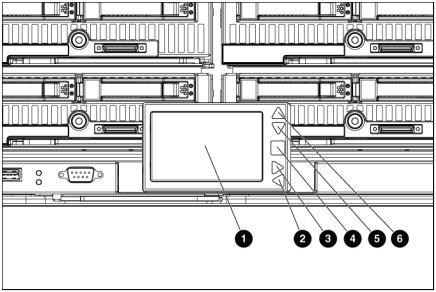
HP BladeSystem c3000 and c7000 3-inch Insight Display components
Item |
Description |
Function |
|
|
|
1 |
Insight Display screen |
Displays Main Menu error messages and instructions |
2 |
Left arrow button |
Moves the menu or navigation bar selection left one position |
3 |
Right arrow button |
Moves the menu or navigation bar selection right one position |
4 |
OK button |
Accepts the highlighted selection and navigates to the selected |
|
|
menu |
5 |
Down arrow button |
Moves the menu selection down one position |
6 |
Up arrow button |
Moves the menu selection up one position |
|
|
|
Insight Display overview
The Insight Display enables the rack technician to initially configure the enclosure. It also provides information about the health and operation of the enclosure. The color of the Insight Display varies with the condition of the enclosure health:
•Blue—The Insight Display illuminates blue when the enclosure UID is active. The enclosure UID is automatically turned on when the enclosure is powered up for the first time, and can be turned by selecting Turn Enclosure UID On from the Main Menu or by pressing the enclosure UID button on the management interposer.
When the enclosure UID is on, the Insight Display flashes after two minutes of inactivity. Pressing any button on the Insight Display stops the blinking and reactivates the screen.
•Green—The Insight Display illuminates green when no error or alert conditions exist, and the enclosure is operating normally. After two minutes of inactivity, the Insight Display light turns off. Pressing any button on the Insight Display reactivates the screen.
•Amber—The Insight Display illuminates amber when the Onboard Administrator detects an error or alert condition. The details of the condition display on the screen.
HP BladeSystem Insight Display 30
Loading...