


|
|
|
|
|
TABLE OF CONTENTS |
|
|
|
|
|
|
Models 78670A/78671A |
|
|
|
|
|
|
|
78670-1 |
|
|
|
|
TABLE OF CONTENTS |
|
|
1 |
GENERAL |
|
|
|
|
|
|
1.1 |
INTRODUCTION |
|
|
1-1 |
|
|
1.2 |
IDENTIFICATION |
|
1-1 |
||
|
1.3 |
INQUIRES |
|
|
1-1 |
|
|
1.4 |
DESCRIPTION |
|
|
1-2 |
|
|
|
1.4.1 |
General |
|
|
1-2 |
|
|
1.4.2 |
Model 78670A Defibrillator/Monitor with Annotating Recorder |
. . 1-3 |
||
|
|
1.4.3 |
Model |
78671A Defibrillator/Monitor/Recorder |
1-4 |
|
|
|
1.4.4 |
Monitor |
|
|
1-4 |
|
|
1.4.5 |
Recorder |
|
1-4 |
|
|
|
1.4.6 |
Defibrillator Output |
Information |
1-5 |
|
|
|
1.4.7 |
Self Diagnostics |
|
1-5 |
|
|
|
1.4.8 |
Defibrillator Charge Time |
1-6 |
||
|
|
1.4.9 |
Paddles |
|
|
1-6 |
|
1.5 |
MODEL |
78670A/78671A OPERATING CONTROLS |
1-7 |
||
|
1.6 |
OPTIONS |
|
|
1-13 |
|
|
1.7 |
GENERAL INSTALLATION INFORMATION |
1-13 |
|||
|
|
1.7.1 |
Initial |
Inspection |
|
1-13 |
|
|
1.7.2 |
Claims |
and Repackaging |
1-13 |
|
|
1.8 |
PREPARING FOR OPERATION |
|
1-14 |
||
|
1.9 |
ENVIRONMENT |
|
|
1-14 |
|
|
|
1.9.1 |
Operating Environment |
|
1-14 |
|
|
|
1.9.2 |
Storage |
and Shipment |
Environment |
1-14 |
|
1.10 |
POWER |
REQUIREMENTS (MODEL |
78668A POWER BASE) |
1-15 |
|
1.11INSTRUMENT GROUNDING AND POWER CORD SETS (78668A POWER BASE) . . . 1-15
1.12 |
MOUNTING |
(78668A POWER BASE) |
1-15 |
1.13 |
OPTIONAL |
ACCESSORY CABLES |
1-17 |
2 THEORY OF OPERATION |
|
||
2.1 |
INTRODUCTION |
2-1 |
|
2.2 |
SYSTEM OVERVIEW |
2-1 |
|
|
2.2.1 |
ECG |
Switch |
Board and Analog Board |
2-1 |
|
2.2.2 |
Digital ECG |
Circuits |
2-2 |
|
|
2.2.3 |
CRT Timing Circuit and Memory |
2-2 |
||
|
2.2.4 |
CRT Driver Circuit |
2-2 |
||
|
2.2.5 |
Heart |
Rate Circuit |
2-2 |
|
|
2.2.6 |
Real |
Time Clock |
2-2 |
|
|
2.2.7 |
Recorder Circuit |
2-2 |
||
|
2.2.8 |
Defibrillator Control |
2-3 |
||
|
2.2.9 |
Defibrillator H.V. Circuits |
2-3 |
||
|
2.2.10 |
Low Voltage and CRT Power Supply |
2-4 |
||
|
2.2.11 |
Battery and |
Battery Relay |
2-4 |
|
|
2.2.12 |
Quick-Mount Power Base 78668A |
2-4 |
||
|
2.2.13 |
Spare Battery Charger 78669A |
2-4 |
||
2.3 |
DETAILED THEORY OF |
OPERATION |
2-7 |
||
|
2.3.1 |
ECG Switch Board 78670-60215 |
2-7 |
||
|
2.3.1.1 |
ECG Source Switch |
2-7 |
||
|
2.3.1.2 |
Protective Circuitry |
2-7 |
||
|
2.3.2 |
ECG Analog Board 78670-60155 |
2-7 |
||
|
2.3.2.1 |
Protection Circuitry |
2-7 |
||
|
2.3.2.2 |
Differential Amplifier |
2-8 |
||
|
2.3.2.3 |
Right |
Leg Drive (RLD) |
2-8 |
|
TABLE OF CONTENTS
Models 78670A/78671A
78670-1 |
|
|
|
|
|
|
|
|
|
2.3.2.4 |
ECG Leads |
Off |
Indicator |
|
2-9 |
|
|||
2.3.2.5 |
Chopper Modem and Power Supply |
2-10 |
|
||||||
2.3.2.6 |
EMI Rejection |
|
|
|
2-10 |
|
|||
2.3.2.7 |
Chopper Driver |
|
|
2-11 |
|
||||
2.3.2.8 |
Baseline Restore |
|
2-11 |
|
|||||
2.3.2.9 |
Fixed |
Gain |
Stage |
|
2-12 |
|
|||
2.3.2.10 |
Zero Offset |
Potentiometer |
|
2-12 |
|
||||
2.3.2.11 |
Calibration |
Potentiometer |
|
2-12 |
|
||||
2.3.2.12 |
Analog Power Supply |
|
2-12 |
|
|||||
2.3.2.13 |
Electromagnetic Interference |
Rejection |
2-12 |
|
|||||
2.3.2.14 |
Paddle Contact |
(PC) |
|
2-13 |
|
||||
2.3.3 |
ECG Digital |
Circuit |
Board |
|
2-14 |
|
|||
2.3.3.1 |
50/60 Hz Notch |
Filter |
|
2-14 |
|
||||
2.3.3.2 |
Auto Gain Attenuator |
|
2-14 |
|
|||||
2.3.3.3 |
Manual Variable |
Gain |
|
2-14 |
|
||||
2.3.3.4 |
Voltage to Frequency Converter (V/F) |
2-15 |
|
||||||
2.3.3.5 |
Auto |
Bias |
|
|
|
|
2-15 |
|
|
2.3.3.6 |
Microprocessor |
|
|
2-15 |
|
||||
2.3.4 |
Microprocessor Reset |
"Tickle" Circuit |
2-16 |
|
|||||
2.3.4.1 |
Beeper |
|
|
|
|
2-17 |
|
||
2.3.4.2 |
Electromagnetic |
Interference |
Rejection |
2-17 |
|
||||
2.3.5 |
Memory/Display Board |
78660-60170 |
|
2-17 |
|
||||
2.3.5.1 |
Functional |
Overview |
|
2-17 |
|
||||
2.3.5.2 |
Oscillator |
and |
Johnson Counter |
2-19 |
|
||||
2.3.5.3 |
1025 |
Counter |
|
|
|
2-19 |
|
||
2.3.5.4 |
Delay ECG Gate (1026 count) |
|
2-19 |
|
|||||
2.3.5.5 |
Address Counter |
|
2-20 |
-^ |
|||||
2.3.5.6 |
RAM Read-Write |
|
|
2-20 |
^ |
||||
2.3.5.7 |
Bidirectional |
Data Bus |
|
2-20 |
|
||||
2.3.5.8 |
Digital to Analog Converter (D/A) |
2-20 |
|
||||||
2.3.5.9 |
Sample and Hold |
|
|
2-20 |
|
||||
2.3.5.10 |
Ramp Generator |
|
|
2-21 |
|
||||
2.3.5.11 |
Analog Multiplexer (MUX) |
|
2-22 |
|
|||||
2.3.6 |
Deflection |
Board |
78660-60180 |
|
2-22 |
|
|||
2.3.6.1 |
Vertical Amplifier |
|
2-22 |
|
|||||
2.3.6.2 |
Horizontal |
Amplifier |
|
2-23 |
|
||||
2.3.6.3 |
Intensity |
Driver |
|
2-23 |
|
||||
2.3.7 |
Clock/Heart |
Rate Board 78660-60260 |
|
2-24 |
|
||||
2.3.7.1 |
Heart |
Rate |
Circuit |
|
2-24 |
|
|||
2.3.7.2 |
Heart |
Rate |
Digital Display |
|
2-24 |
|
|||
2.3.7.3 |
Language Option |
Selector |
|
2-24 |
|
||||
2.3.7.4 |
Heart |
Rate |
Alarm Switch |
|
2-24 |
|
|||
2.3.7.5 |
Clock |
Circuit |
|
|
|
2-25 |
|
||
2.3.7.6 |
Voltage Reference |
|
2-27 |
|
|||||
2.3.7.7 |
Clock |
Battery |
|
|
|
2-27 |
|
||
2.3.7.8 |
Clock |
Protection |
|
2-27 |
|
||||
2.3.7.9 |
Clock |
Crystal |
|
|
|
. . . 2-27 |
|
||
2.3.8 |
Recorder Control |
Board 78660-60200 |
|
2-27 |
|
||||
2.3.8.1 |
ECG Monitor to Recorder Signal |
2-27 |
|
||||||
2.3.8.2 |
ECG Memory to Recorder Signal |
|
2-27 |
|
|||||
2.3.8.3 |
Recorder Movement and Stylus Heat Control |
2-28 |
|
||||||
2.3.8.4 |
Recorder/Signal |
Control |
|
2-28 |
|
||||
2.3.8.5 |
ECG Signal Amplitude Limiting and Switching |
2-28 |
|
||||||
2.3.8.6 |
Microprocessor |
Reset (Tickle) |
Circuit |
2-29 |
|
||||
2.3.8.7 |
Print Head Driver |
2-30 |
|
|
|
|
|
|
TABLE OF CONTENTS |
|
|
|
|
|
|
Models 78670A/78671A |
|
|
|
|
|
|
78670-1 |
2.3.8.8 |
Head Protective Circuit |
2-31 |
||||
2.3.8.9 |
Input/Output |
Lines |
2-31 |
|||
2.3.9 |
Defibrillator Control Circuit Board 78670-60195 |
2-32 |
||||
2.3.9.1 |
Microprocessor |
2-32 |
||||
2.3.9.2 |
"Ticke!" Reset Circuit |
2-32 |
||||
2.3.9.3 |
LCD Drivers and Recorder Data |
2-33 |
||||
2.3.9.4 |
Analog Multiplexer and A/D Converter |
2-34 |
||||
2.3.9.5 |
I/O Expander |
|
|
2-34 |
||
2.3.9.6 |
Relay |
Drivers |
|
2-34 |
||
2.3.9.7 |
Charge |
Done Tone |
2-34 |
|||
2.3.9.8 |
Battery LED |
Driver |
2-34 |
|||
2.3.9.9 |
Paddle |
Contact |
Chopper |
2-35 |
||
2.3.9.10 |
Monitoring |
the HV Capacitor |
2-37 |
|||
2.3.9.11 |
Charge and Discharge Cycle |
2-37 |
||||
2.3.9.12 |
Cardioversion |
|
2-38 |
|||
2.3.9.13 |
Software Safety Features |
2-38 |
||||
2.3.10 |
Defibrillator High |
Voltage Section |
2-38 |
|||
2.3.10.1 |
General |
|
|
2-38 |
||
2.3.10.2 |
Power Circuits |
2-39 |
||||
2.3.11 |
Pulse Width |
Modulator |
2-39 |
|||
2.3.11.1 |
PWM Shutdown |
|
2-40 |
|||
2.3.11.2 |
Soft Start |
|
|
2-40 |
||
2.3.12 |
HV Defibrillator |
Inverter Circuit |
2-40 |
|||
2.3.12.1 |
HV Monitor |
Circuit |
2-41 |
|||
2.3.12.2 |
Patient Relay |
Circuit |
2-42 |
|||
2.3.12.3 |
Peak |
Current |
Detector Circuit |
2-43 |
||
2.3.12.4 |
Safety Relay |
Circuit |
2-44 |
|||
2.3.12.5 |
5.4 V Reference/Low Battery Shutdown |
2-44 |
||||
2.3.13 |
Low Voltage |
Power Supply Board 78660-60110 |
2-46 |
|||
2.3.13.1Pulse Width Modulator (PWM) Internal Circuits .... 2-46
2.3.13.2 |
External PWM |
Circuits |
2-48 |
||
2.3.13.3 |
5V. |
Supply Voltage |
Regulation |
2-50 |
|
2.3.13.4 |
CRT |
Supplies |
(+5000 |
and +200 volts) |
2-52 |
2.3.13.5+ and -15 Volt Supplies (Refer to Figure 2-62) .... 2-53
|
2.3.13.6 |
+ and -12 Volt Supplies |
2-53 |
||||
|
2.3.13.7 |
Noise Filtering |
|
2-53 |
|||
|
2.3.14 |
Service |
Switch |
|
|
2-53 |
|
|
2.3.15 |
Annotation Printout |
|
2-54 |
|||
CHECKS AND ADJUSTMENTS |
|
|
|
||||
3.1 |
INTRODUCTION |
|
|
|
|
3-1 |
|
3.2 |
LEVEL |
II PERFORMANCE, SAFETY AND |
MAINTENANCE CHECKS |
3-1 |
|||
|
3.2.1 |
Test Equipment |
|
|
3-1 |
||
|
3.2.2 |
Functional |
Performance Testing |
3-4 |
|||
|
3.2.2.1 |
Energy Accuracy |
|
3-4 |
|||
|
3.2.2.2 |
Self Testing Accuracy |
|
3-5 |
|||
|
3.2.2.3 |
Defibrillator Capacitor Charge Time |
3-5 |
||||
|
3.2.2.4 |
Synchronizer |
'. |
3-5 |
|||
|
3.2.2.5 |
ECG |
Amplifier Noise |
|
3-6 |
||
|
3.2.2.6 |
ECG |
Amplifier Gain |
|
3-6 |
||
|
3.2.2.7 |
Heart Rate Accuracy and Alarm |
3-7 |
||||
|
3.2.2.8 |
Paddle Contact Indicator (PCI) Test |
3-8 |
||||
|
3.2.3 |
Safety |
and |
Maintenance Checks |
3-8 |
||
|
3.2.3.1 |
Preliminary |
Safety Checks |
3-8 |
|||
|
3.2.3.2 |
Power Cord |
to Chassis |
Ground Resistance Check |
3-9 |
||
///
TABLE OF CONTENTS
Models 78670A/78671A
78670-1
3.2.3.3Paddle Leakage Current (Source Leakage) to Ground. . . .3-11
3.2.3.4 |
Paddle Leakage Current (Sink Current) with 115 Volts App 3-12 /r^l |
3.2.3.5Patient Lead Leakage Current (Source Leakage) to Ground. 3-14
3.2.3.6 |
Leakage Current Between Patient Leads Check |
3-15 |
3.2.3.7Patient Lead Leakage Current (Sink Current) with 115 Vol 3-17
|
3.2.3.8 |
Battery Capacity Check |
3-17 |
|
3.3 |
ADJUSTMENTS |
3-18 |
||
|
3.3.1 |
Equipment Required |
3-18 |
|
|
3.3.2 |
Related Adjustments |
3-18 |
|
|
3.3.3 |
Adjustment Location |
3-18 |
|
|
3.3.4 |
Paddle Contact Indicator Adjustment |
3-20 |
|
|
3.3.5 |
Low Voltage Power Supply Adjustments |
3-21 |
|
|
3.3.6 |
ECG |
Cal Adjustment |
3-22 |
|
3.3.7 |
ECG Amplifier Baseline Offset Adjustment |
3-24 |
|
|
3.3.8 |
CRT |
Display Adjustments |
3-25 |
|
3.3.9 |
Real Time Clock/V REF ADJUSTMENT |
3-26 |
|
|
3.3.10 |
Real Time Clock/Heart Rate Frequency Adjustment |
3-27 |
|
|
3.3.11 |
Common Mode Rejection Notch Filter Switches |
3-28 |
|
3.3.12Voltage Reference, Defibrillator Charger Circuit Board . . . 3-29
3.3.13 Defibrillator Output Energy Calibration 3-30
|
3.3.14 |
High Voltage Charge Time Adjust |
3-31 |
||
|
3.3.15 |
Self Test Accuracy |
Adjust |
3-32 |
|
|
3.3.16 |
Recorder Pen Heat |
Adjust |
3-33 |
|
|
3.3.17 |
Recorder Stylus Contact Pressure Adjustment |
3-34 |
||
|
3.3.18 |
Recorder Pen Positioning |
3-35 |
||
|
3.3.19 |
Recorder Print Head Adjustment |
3-36 |
||
|
3.3.20 |
Setting Real Time Clock |
3-37 |
||
3.4 |
SPECIFICATION CHECKS |
|
3-39 |
||
|
3.4.1 |
ECG |
Amplifier/Heart |
Rate Section |
3-39 |
|
3.4.1.1 |
Test Equipment |
3-39 |
||
|
3.4.1.2 |
ECG Amplifier Gain - Manual Control |
3-40 |
||
|
3.4.1.3 |
ECG Amplifier Gain - Auto Mode |
3-41 |
||
|
3.4.1.4 |
Baseline Offset - ECG Lead Input |
3-42 |
||
|
3.4.1.5 |
Baseline Offset - Paddles Input |
3-42 |
||
|
3.4.1.6 |
ECG Amplifier Frequency Response, Leads Input |
3-43 |
||
3.4.1.7ECG Amplifier Frequency Response Check - Paddle Input . 3-43
3.4.1.8 |
Input Offset Tolerance (DC) - ECG Lead Input |
3-44 |
||
3.4.1.9 |
Input Offset Tolerance (DC) - Paddle input |
3-45 |
||
3.4.1.10 |
ECG Amplifier Noise, Leads Input |
3-46 |
||
3.4.1.11 |
ECG Amplifier Noise, Paddles Input |
3-47 |
||
3.4.1.12 |
ECG Calibration Check |
3-48 |
||
3.4.1.13 |
Common Mode Rejection (CMR) Leads Source |
3-49 |
||
3.4.1.14 |
Common Mode Rejection (CMR), Paddles Source |
3-50 |
||
3.4.1.15 |
Heart |
Rate Accuracy |
3-51 |
|
3.4.1.16 |
Heart |
Rate Alarm Limits |
3-51 |
|
3.4.2 |
Recorder Section |
3-52 |
||
3.4.2.1 |
Test Equipment Requirements |
3-52 |
||
3.4.2.2 |
Recorder Frequency Response |
3-53 |
||
3.4.2.3Recorder Gain Accuracy, Linearity, and Overshoot . . . 3-53
3.4.2.4 |
Recorder Chart Speed |
3-54 |
3.4.3 Defibrillator Section |
3-54 |
|
3.4.3.1 |
Test Equipment |
3-54 |
3.4.3.2 |
Energy Accuracy |
3-55 |
3.4.3.3 |
Delivered Energy Waveform Information |
3-56 |
iv
|
|
|
|
|
|
|
TABLE OF CONTENTS |
|
|
|
|
|
|
|
Models 78670A/78671A |
|
|
|
|
|
|
|
78670-1 |
|
3.4.3.4 |
Self Testing Accuracy |
3-56 |
||||
|
3.4.3.5 |
Defibrillator Capacitor Charge Time |
3-57 |
||||
|
3.4.4 |
Synchronizer Section |
|
3.57 |
|||
|
3.4.4.1 |
Test Equipment |
|
3-57 |
|||
|
3.4.4.2 |
R-wave/Sync Pulse/Discharge Delay |
3-58 |
||||
|
3.4.5 |
Paddle |
Contact Indicator |
3-61 |
|||
|
3.4.5.1 |
Test Equipment |
|
3-61 |
|||
|
3.4.5.2 |
Paddle Contact Indicator Test |
3-61 |
||||
MECHANICAL DISASSEMBLY/ASSEMBLY |
|
|
|||||
4.0 |
PRELIMINARY INSTRUCTIONS |
|
4-0 |
||||
4.1 |
MECHANICAL |
DISASSEMBLY |
|
4-1 |
|||
4.2 |
MECHANICAL |
REASSEMBLY |
|
4-2 |
|||
|
4.2.1 |
Replacing the Low Voltage Power Supply Board |
4-4 |
||||
|
4.2.2 |
Paddle/Cable Assembly Replacement |
4-5 |
||||
|
4.2.3 |
Replacing the Defibrillator H.V. Board |
4-8 |
||||
|
4.2.4 |
Replacing H.V. Capacitor |
4-9 |
||||
|
4.2.5 |
Safety |
Relay |
Replacement |
4-10 |
||
|
4.2.6 |
Patient |
Relay |
Replacement |
4-11 |
||
|
4.2.7 |
Circuit |
Board Replacement |
4_12 |
|||
|
4.2.8 |
Recorder Board Assembly Replacement |
4-12 |
||||
|
4.2.9 |
ECG |
Analog Board Replacement |
4-13 |
|||
|
4.2.10 |
Switchboard Replacement |
4-13 |
||||
|
4.2.11 |
CRT |
Replacement |
|
4-13 |
||
|
4.2.12 |
Front |
Panel Removal |
|
4-14 |
||
|
4.2.13 |
Fuse Replacement |
|
4-16 |
|||
|
4.2.14 |
Knob Removal |
|
|
4-16 |
||
|
4.2.15 |
ECG Size, Recorder, Alarm and ECG Source Knobs |
4-16 |
||||
|
4.2.16 |
Knob Replacement |
|
4-17 |
|||
|
4.2.17 |
Energy |
Selection Knob |
|
4-17 |
||
|
4.2.18 |
Recorder Replacement |
|
4-18 |
|||
|
4.2.19 |
Printhead Replacement |
|
4-20 |
|||
|
4.2.20 |
Printhead Adjustment |
|
4-21 |
|||
|
4.2.21 |
Assembly Installation |
|
4-22 |
|||
|
4.2.22 |
QRS |
Beeper Speaker Replacement |
4-22 |
|||
|
4.2.23 |
"Paddles in Place" Reed Switch Replacement |
4-23 |
||||
|
4.2.24 |
ENERGY |
SELECTOR Switch Replacement |
4-24 |
|||
|
4.2.25 |
Other Components Mounted on the Flex Circuit |
4.94 |
||||
|
4.2.26 |
SYNC/DEFIB Switch Replacement |
4.35 |
||||
|
4.2.27 |
Flex Circuit Replacement ... |
4_26 |
||||
|
4.2.28 |
Liquid Crystal Display |
Replacement |
4-26 |
|||
|
4.2.29 |
LCD |
Replacement |
|
4-28 |
||
|
4.2.30 |
LED |
Replacement, Front |
Panel |
4_29 |
||
4.3 |
RECHARGEABLE NICKEL |
CADMIUM BATTERY - Bl |
4.29 |
||||
|
4.3.1 |
General |
Description |
|
4_29 |
||
|
4.3.2 |
Charge Retention |
|
4_29 |
|||
|
4.3.3 |
Charging |
|
|
4_30 |
||
|
4.3.4 |
Voltage Depression (Memory) |
4_30 |
||||
|
4.3.5 |
What To Do About It |
|
4.30 |
|||
|
4.3.6 |
Cell |
Reversal |
|
|
4_3q |
|
|
4.3.7 |
Battery |
Replacement |
|
4_31 |
||
|
4.3.8 |
Storage |
of Nickel Cadmium Batteries |
a 01 |
|||
4.4 |
RECORDER STYLUS REPLACEMENT |
J^f |
TABLE OF CONTENTS
Models 78670A/78671A
78670-1
5 TROUBLESHOOTING
|
5.1 |
INTRODUCTION |
|
|
|
5-1 |
||
|
5.2 |
BOARD |
LEVEL |
|
|
|
5-1 |
|
|
|
5.2.1 |
System Problems |
|
5-2 |
|||
|
|
5.2.2 |
Defibrillator H.V. Problems |
5-2 |
||||
|
|
5.2.3 |
LCD Readout Problems |
|
5-4 |
|||
|
|
5.2.4 |
ERROR Messages on LCD |
|
5-5 |
|||
|
|
5.2.5 |
CRT |
Display |
Problems |
|
5-6 |
|
|
|
5.2.6 |
Recorder Problems |
|
5-7 |
|||
|
|
5.2.7 |
Indicator Malfunction |
|
5-9 |
|||
|
|
5.2.8 |
ECG |
Signal |
|
Problems |
|
5-10 |
|
|
5.2.9 |
Real |
Time |
Clock Problems |
5-11 |
||
|
|
5.2.10 |
Control Problems |
|
5-11 |
|||
|
|
5.2.11 |
Service Mode |
|
5-12 |
|||
|
|
5.2.12 |
Battery Power Base Problems |
5-12 |
||||
|
5.3 |
COMPONENT |
LEVEL |
|
|
|
5-13 |
|
|
|
5.3.1 |
ECG Monitor |
|
|
5-14 |
||
|
|
5.3.2 |
ECG |
Analog |
|
Board (A3) |
|
5-14 |
|
|
5.3.2.1 |
ECG |
Section |
|
5-15 |
||
|
|
5.3.2.2 |
ECG Differential Amplifier Test Procedure |
5-16 |
||||
|
|
5.3.2.3 |
Bias Voltage Check Procedure on Differential Amplifier |
5-16 |
||||
|
|
5.3.2.4 |
Paddle Contact |
Indicator |
5-17 |
|||
|
|
5.3.3 |
Digital ECG Board (A-4) |
5-17 |
||||
|
|
5.3.4 |
Memory Board (A5) |
|
5-22 |
|||
|
|
5.3.5 |
Deflection |
Board (A6) |
|
5-25 |
||
|
|
5.3.6 |
Clock/Heart |
Rate Board (A7) |
5-26 |
|||
|
|
5.3.7 |
Recorder Board (A8) |
|
5-30 |
|||
|
|
5.3.7.1 |
Annotation (78670A Only) |
5-31 |
||||
|
|
5.3.7.2 |
CRT |
Digits |
|
5-34 |
||
|
|
5.3.7.3 |
Switch Functions |
5-36 |
||||
|
|
5.3.7.4 |
Recorder |
|
5-37 |
|||
|
|
5.3.8 |
Defibrillator Control |
Board (A10) |
5-39 |
|||
|
|
5.3.8.1 |
Error Messages |
|
5-39 |
|||
|
|
5.3.8.2 |
LCD |
Display |
|
5-40 |
||
|
|
5.3.8.3 |
Paddle Contact |
Indicator |
5-41 |
|||
|
|
5.3.9 |
Defibrillator Charger Board (A-ll) |
5-41 |
||||
|
|
5.3.10 |
Pulse Width Modulator (A12-U1) |
5-55 |
||||
6 |
REPLACEABLE PARTS AND SCHEMATIC DIAGRAMS |
|
||||||
|
6.1 |
INTRODUCTION |
|
|
|
6-1 |
||
|
6.2 |
REFERENCE |
DESIGNATIONS |
|
6-1 |
|||
|
6.3 |
ORDERING INFORMATION |
|
6-2 |
||||
7 |
ACCESSORIES |
|
|
|
|
|
||
|
7.1 |
78668A Quick-Mount Power Base |
7-1 |
|||||
|
|
7.1.1 |
Theory of Operation - AC Circuits |
7-1 |
||||
|
|
7.1.2 |
Regulated |
Voltage Circuit |
7-1 |
|||
|
|
7.1.3 |
Raw Voltage and Battery Charge Circuit |
7-2 |
||||
|
|
7.1.4 |
Low |
Line Voltage Circuit |
7-2 |
|||
|
|
7.1.4.1 |
Disassembly |
|
7-2 |
|||
|
|
7.1.5 |
Troubleshooting Power Base |
7-3 |
||||
|
7.2 |
BATTERY CHARGER |
78669A |
|
7-9 |
|||
VI
|
|
|
|
|
|
|
|
|
|
|
|
|
TABLE OF CONTENTS |
|
|
|
|
|
|
|
|
|
|
|
|
|
Models 78670A/78671A |
|
|
|
|
|
|
|
|
|
|
|
|
|
78670-1 |
|
7.2.1 |
Description |
|
|
|
7-9 |
|||||||
|
7.2.2 |
Charging |
|
|
|
|
7-9 |
||||||
|
7.2.3 |
Indicator Lamps |
|
|
7-9 |
||||||||
|
7.2.4 |
Battery Charger Theory of Operation |
7-10 |
||||||||||
|
7.2.5 |
Current |
Source |
|
|
7-10 |
|||||||
|
7.2.6 |
Circuit |
Voltage |
Regulator |
7-10 |
||||||||
|
7.2.7 |
Timing |
Oscillator |
|
.7-11 |
||||||||
|
7.2.8 |
Clock |
|
Gate |
|
|
|
7-11 |
|||||
|
7.2.9 |
Divide |
By 2048 and Divide By 4096 Counters |
7-11 |
|||||||||
|
7.2.10 |
|
Counter Reset |
Gate |
|
7-11 |
|||||||
|
7.2.11 |
|
Maintenance |
|
|
7-12 |
|||||||
|
7.2.12 |
|
Disassembly |
|
|
7-12 |
|||||||
|
7.2.13 |
|
Troubleshooting Battery Charger |
7-15 |
|||||||||
7.3 |
RECHARGEABLE |
NICKEL CADMIUM BATTERY - Bl |
7-19 |
||||||||||
|
7.3.1 |
|
General |
Description |
|
7-19 |
|||||||
|
7.3.2 |
|
Charge |
Retention |
|
7_19 |
|||||||
|
7.3.3 |
|
Charging |
|
|
|
|
7-19 |
|||||
|
7.3.4 |
|
Voltage |
Depression (Memory) |
7-20 |
||||||||
|
7.3.6 |
|
Cell |
Reversal |
|
|
7-20 |
||||||
|
7.3.7 |
|
Battery Replacement 78660-60401 |
7-20 |
|||||||||
|
7.3.8 |
|
Storage |
of |
Nickel Cadmium Batteries |
7-21 |
|||||||
OPTIONS |
|
|
|
|
|
|
|
|
|
|
|
8-1 |
|
|
|
|
|
|
|
|
|
|
|
LIST OF ILLUSTRATIONS |
|
||
FIGURE |
|
|
|
|
|
|
|
|
|
TITLE |
PAGE |
||
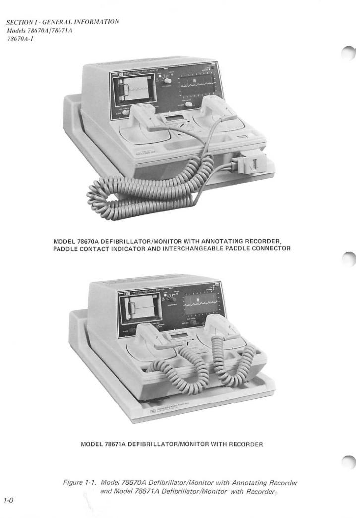
1-1 |
Front |
View Model |
78670A/7861A Defibrillator |
1-0 |
|||||||||
1-2 |
Defibrillator Waveform |
|
|
1-5 |
|||||||||
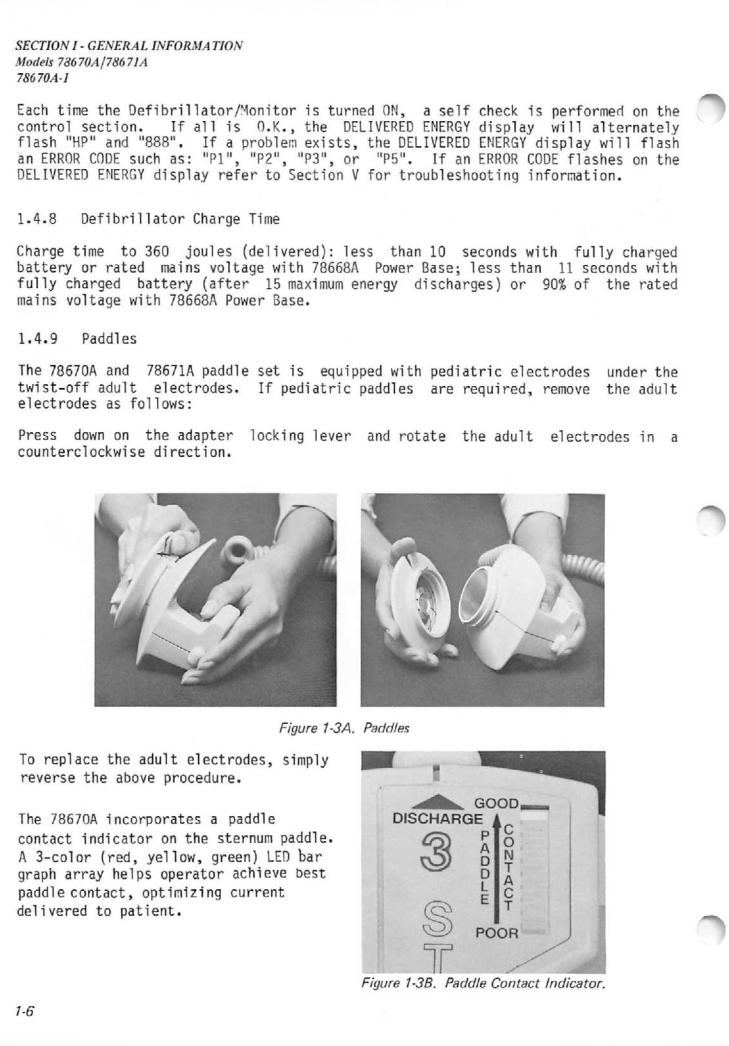
1-3A |
Paddles |
|
|
|
|
|
|
|
|
|
|
1-6 |
|
1-3B |
Paddle |
Contact |
Indicator |
|
1-6 |
||||||||
1-4 |
Model |
78670A |
and |
78671A Controls |
1-7 |
||||||||
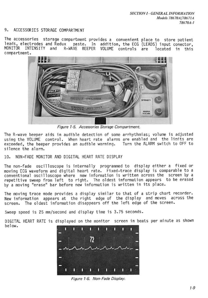
1-5 |
Accessories |
Storage |
Compartment |
1-9 |
|||||||||
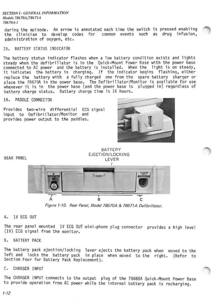
1-6 |
Non-Fade |
Display |
|
|
|
|
|
1-9 |
|||||
1-7 |
Date |
Time |
Annotation |
|
|
|
1-11 |
||||||
1-8 |
Stored |
and Delivered |
Energy Annotation |
1-11 |
|||||||||
1-9 |
Heart |
Rate |
and Marker Annotation |
1-11 |
|||||||||
1-10 |
Rear |
Panel, |
Model |
78670A and |
78671A |
1-12 |
|||||||
2-1 |
Model |
78670A Block |
Diaqram |
|
2-1 |
||||||||
2-2 |
Detailed |
Block |
|
Diagram, |
Model |
78670A Foldout |
. 2 - 6 |
||||||
2-3 |
ECG Source |
Switch |
|
|
|
|
2-7 |
||||||
2-4 |
Protective |
Circuitry |
|
|
|
2-8 |
|||||||
2-5 |
Differential Amplifier |
|
|
2-8 |
|||||||||
2-6 |
Right |
Leg |
Drive |
Circuit |
|
|
2-9 |
||||||
2-7 |
ECG Leads |
Off |
Indicator |
Circuit |
2-9 |
||||||||
2-8 |
Chopper Modem |
and Power Supply |
2-10 |
||||||||||
2-9 |
Chopper |
Driver Circuit |
|
|
2-11 |
||||||||
2-10 |
Baseline |
Restore |
Circuit |
|
|
2-11 |
|||||||
2-11A Fixed Gain Stage |
|
|
|
|
|
2-12 |
|||||||
2-11S |
Paddle |
Contact |
|
|
|
|
|
|
|
2-13 |
|||
vii
TABLE OF CONTENTS
Models 78670A/78671A
78670-1
2-12 |
50/60 Hz Notch Filter Circuit |
2-14 |
|||
2-13 |
Auto Gain Attenuator |
|
2-15 |
||
2-14 |
Voltage to Frequency |
Converter |
2-16 |
||
2-15 |
Auto Bias |
Circuit |
|
2-16 |
|
2-16 |
Microprocessor Reset |
(Tickle) Circuit |
2-16 |
||
2-17 |
CRT Display and Blanking Timing |
2-17 |
|||
2-18A Read/Write Sequence Delay Mode |
2-18 |
||||
2-18B Read/Write Sequence Fixed Trace Mode |
2-18 |
||||
2-19 |
Erase Bar Generator |
|
2-19 |
||
2-20 |
Oscillator and Johnson Counter |
2-19 |
|||
2-21 |
1025 and 1026 Count Circuit |
2-20 |
|||
2-22A |
Memory to CRT Circuit Block Diagram |
2-21 |
|||
2-22B |
Memory to Recorder and Output Block Diagram |
2-21 |
|||
2-23 |
Ramp Generator |
|
2-21 |
||
2-24 |
Multiplex |
Driver Timing |
2-22 |
||
2-25 |
Deflection Amplifier Block Diagram |
2-22 |
|||
2-26 |
CRT Intensity Driver |
|
2-23 |
||
2-27 |
CRT Blanking Circuit |
|
2-23 |
||
2-28 |
Clock/Heart Rate Board Block Diagram |
. 2-24 |
|||
2-29 |
Clock |
Circuit |
|
2-25 |
|
2-30 |
Timing |
Diagram |
|
2-25 |
|
2-31 |
Clock |
Circuit Read Cycle Timing |
2-26 |
||
2-32 |
Clock Circuit Time Set Cycle Timing |
2-26 |
|||
2-33 |
Recorder Control Circuit |
2-28 |
|||
2-34 |
Recorder ECG Amplitude Limit Circuit |
2-28 |
|||
2-35 |
Microprocessor Reset |
(Tickle) Circuit |
2-29 |
||
2-36 |
Microprocessor Reset Oscillator Equivalent Circuit |
2-29 |
|||
2-37 |
Microprocessor Reset |
Pulses |
2-29 |
||
2-38 |
Printhead |
Driver Circuit |
2-30 |
||
2-39 |
A8-U2 Drive Signal |
|
2-31 |
||
2-40 |
Printhead |
Protection |
Circuit |
2-31 |
|
2-41 |
"Ticker |
Reset Circuit |
2-32 |
||
2-42 |
LCD Timing |
|
2-33 |
||
2-43 |
Charge Done Tone |
|
2-35 |
||
2-44 |
Paddle Contact Chopper |
2-35 |
|||
2-45 |
HV Capacitor Monitoring Circuit |
2-37 |
|||
2-46 |
Pulse Width Modulator |
2-39 |
|||
2-47 |
PWM Shutdown |
|
2-40 |
||
2-48 |
HV Defibrillator Inverter Circuit |
2-41 |
|||
2-49 |
HV Monitor Circuit, |
|
2-42 |
||
2-50 |
Patient |
Relay Circuit |
2-43 |
||
2-51 |
Peak Dicharge Current Detector Circuit |
2-44 |
|||
2-52 |
Safety Relay Circuit |
|
2-45 |
||
2-53 |
5.4 V Reference and Low Battery Shutdown Circuit |
2-45 |
|||
5-54 |
Low Voltage Power Supply Block Diagram |
2-46 |
|||
2-55 |
Pulse Width Modulator Block Diagram |
2-47 |
|||
2-56 |
Pulse Width Modulator External Circuit |
2-48 |
|||
2-57 |
Flyback |
Driver Circuit |
2-49 |
||
2-58 |
Low Battery Detector Circuit |
2-50 |
|||
2-59 |
Low Voltage Supply DC Output Circuit |
2-51 |
|||
2-60 |
Flyback Transformer CRT Supply Waveform |
2-52 |
|||
2-61 |
CRT Supply Regulator |
2-52 |
|||
3-0 |
Circuit Board Locator |
3-0 |
|||
3-1 |
Energy Accuracy Test |
Setup |
3-4 |
||
3-2 |
Five |
Gain Stages of AUTO |
3-7 |
||
via
|
|
|
|
|
|
TABLE OF CONTENTS |
|
|
|
|
|
|
Models 78670A178671A |
|
|
|
|
|
|
78670-1 |
3 - 3 |
Heart Rate Accuracy and Alarm |
3-7 |
||||
3-4 |
Power Cord to Chassis Ground Resistance Check |
3-9 |
||||
3-5 |
Test Connections to Paddles |
3-10 |
||||
3-6 |
Paddle Leakage Current to Ground |
3-10 |
||||
3-7A |
Paddle Leakage Test with 115V Applied |
3-11 |
||||
3-7B |
Paddle Leakage Test with 115V Applied |
3-12 |
||||
3-8A |
Patient Lead Leakage Current to Ground Test |
3-13 |
||||
3-8B Patient Lead Leakage Current to Ground Test |
3-13 |
|||||
3-9A |
Leakage Current Between Patient Leads Test |
3-14 |
||||
3-9B |
Leakage Current Between Patient Leads Test |
3-15 |
||||
3-10A |
Patient Lead Leakage Current Test with 115 V Applied |
3-16 |
||||
3-10B |
Patient |
Lead |
Leakage Current Test with 115 V Applied |
3-16 |
||
3-11 Test Setup for Battery Capacity Check |
3-17 |
|||||
3-12A |
ECG Amplifier Gain and Frequency Response Test Setup |
3-40 |
||||
3-12B |
ECG Amplifier Gain |
and Frequency Response Test Setup |
3-40 |
|||
3-13 |
ECG Amplifier Baseline Offset (Leads) |
3-42 |
||||
3-14 |
ECG Amplifier Baseline Offset (Paddles) |
3-42 |
||||
3-15 |
ECG Amplifier Frequency Response Setup (Paddles) |
3-44 |
||||
3-16 |
Input Offset Tolerance (DC) Leads Test Setup |
3-44 |
||||
3-17 |
ECG Amplifier Noise, Leads Input Test Setup |
3-46 |
||||
3-18 |
ECG Amplifier Noise, Paddle Input Test Setup |
3-47 |
||||
3-19 |
Calibration Step Waveform |
3-48 |
||||
3-20 |
Common Mode Rejection Test Setup (Leads) |
3-49 |
||||
3-21 Common Mode Rejection Test Setup (Paddles) |
3-51 |
|||||
3-22 |
Heart Rate Accuracy Test Setup |
3-51 |
||||
3-23 |
Service Mode |
Test Pattern, Recorder |
3-53 |
|||
3-24 |
Energy |
Accuracy Test Setup |
3-55 |
|||
3-25 |
R Wave/Sync Pulse/Discharge Delay Test Setup |
3-58 |
||||
3-26 |
ECG Output Waveform |
3-59 |
||||
3-27 |
R Wave |
|
|
|
|
3-59 |
3-28 |
Sync Pulse Superimposed on R Wave |
3-60 |
||||
3-29 |
R Wave/Sync Pulse/Discharge Pulse Relationship |
3-60 |
||||
4-1 |
Screw Locations for Disassembly |
4-1 |
||||
4-2 |
Inside |
View of 78670A |
4-2 |
|||
4-3 |
Circuit Board Shield Removal (78670A) |
4-3 |
||||
4-4 |
Low Voltage Power Supply Board Removal(78671A) |
4-4 |
||||
4-5 |
Defibrillator Charger Board Removal (78671A) |
4-6 |
||||
4-6 |
H.V. Component |
Servicing (78671A) |
4-6 |
|||
4-7 |
Cable Housing Assembly Removal (78671A) |
4-7 |
||||
4-8 |
Paddle |
Cable |
Replacement(78671A) |
4-7 |
||
4-9 |
Paddle |
Cable |
Replacement (78671A) |
4-8 |
||
4-10 |
Upper Housing Circuit Board Location |
4-11 |
||||
4-11 |
Front Panel |
Removal |
4-14 |
|||
4-12 |
Front Panel |
Removal |
4-14 |
|||
4-13 |
CRT Removal |
|
|
|
4-15 |
|
4-14 |
CRT Yoke Assembly |
|
4-15 |
|||
4-15 |
Mother Board Fuse Location A2-F1 and F2 |
4-15 |
||||
4-16 |
ECG Knob Removal |
|
4-17 |
|||
4-17 |
Energy |
Select |
Knob |
Removal |
4-17 |
|
4-18 |
Energy |
Select |
Knob |
Removal |
4-17 |
|
4-19 |
Recorder Assembly |
Removal |
4-19 |
|||
4-20 |
Recorder Assembly |
|
4-19 |
|||
4-21 |
Recorder Mechanism |
|
4-20 |
|||
4-22 |
Detail |
of Printhead |
4-21 |
|||
IX
TABLE OF CONTENTS
Models 78670A/78671A
78670-1
4-23 |
Top View of Recorder Housing and Beeper Speaker |
4-23 |
/1*% |
|||||
4-24 |
Front Panel Mounted Components on Upper Housing |
4-24 |
' |
|||||
4-25 |
Flex |
Circuit |
Assembly |
(A16) |
4-25 |
|
||
4-26 |
LCD |
Removal |
|
Sequence |
|
|
4-27 |
|
4-27 |
LCD |
Removal |
|
Sequence |
|
|
4-27 |
|
4-28 |
LCD |
Removal |
|
Sequence |
|
|
4-27 |
|
6-1 |
System Block |
Diagram |
|
|
6-5/6 |
|
||
6-2 |
Schematic, |
Mother Board A2 |
6-7/8 |
|
||||
6-3 |
Schematic, ECG Analog Board A3 |
6-9/10 |
|
|||||
6-4 |
Schematic, |
ECG Digital Board A4 |
6-11/12 |
|
||||
6-5 |
Schematic, |
Memory Board |
A5 |
6-13/14 |
|
|||
6-6 |
Schematic, |
Deflection |
Board A6 |
6-15/16 |
|
|||
6-7 |
Schematic, Clock/Heart Rate Board A7 |
6-17/18 |
|
|||||
6-8 |
Schematic, Recorder Control Board A8 |
6-19/20 |
|
|||||
6-9 |
Recorder Assembly A9 |
|
|
6-21/22 |
|
|||
6-10 |
Schematic, Defibrillator Control Board A10 |
6-23/24 |
|
|||||
6-11 |
Schematic, Defibrillator Charger Board A11 |
6-25/26 |
|
|||||
6-12 |
Schematic, |
Low Voltage Power Supply Board A12 |
6-27/28 |
|
||||
6-14 |
Schematic, |
Flex Circuit |
Assembly A16 |
6-29/30 |
|
|||
6-15 |
Schematic, Heart Rate Board A17 |
6-31/32 |
|
|||||
6-16 |
78670A Case |
|
Assembly |
A1 |
|
6-33/34 |
|
|
|
78670A Case |
|
Assembly |
(cont.) |
6-35/36 |
|
||
6-17 |
Receptacle |
Cable Assembly |
6-37/38 |
|
||||
6-18 |
78671A Case Assembly |
A1 |
6-39/40 |
|
||||
7-1 |
O'iic'<-X,.ount 0o\iw vise |
|
7-1 |
--•% |
||||
7-2 |
Quick-Mount Power Base |
(Bottom View) |
7-3 |
/ |
||||
7-3 |
Quick-Mount Power Base |
Inner Circuitry |
7-3 |
|
||||
7-4 |
Schematic, |
Power Supply |
Board |
7-7/? |
|
|||
7-5 |
78669A Battery Charger |
|
7-0 |
|
||||
7-6 |
Timing Diagram |
|
|
7-11 |
|
|||
7-7 |
Top Cover Removal |
|
|
7-f |
|
|||
7-8 |
Bottom Cover Removal |
|
|
7-13 |
|
|||
7-9 |
Removing Heat Radiator |
|
7-13 |
|
||||
7-10 |
Battery Charger with Top Cover Removed |
7-H |
|
|||||
7-11 |
Battery Charger with Bottom Cover Removed |
7-14 |
|
|||||
7-12 |
Battery Charger Circuit |
Board |
7-15 |
|
||||
7-13 |
Schematic, |
Battery Charger Board |
7-17/1'3 |
|
||||
8-1 |
78670A, Option A03 Case Assembly |
8-9/10 |
|
|||||
TABLE OF CONTENTS
Models 78670A178671A
78670-1
TABLES
TABLE TITLE PAGE
1-1 |
Model 78670A Defibrillator/Monitor with Annotating Recorder Specs . |
1-2 |
|||||
1-2 |
Model |
78671A Defibrillator/Monitor/Recorder Specs |
1-3 |
||||
1-3 |
Power Cable Sets |
|
|
|
1-16 |
||
3-1 |
Required |
Test Equipment |
for Level |
II Performance, |
|
||
|
Safety |
and Maintenance Tests |
|
3-2 |
|||
3-2 |
Equipment Necessary |
if the Dempsey |
Model 431F |
|
|||
|
Safety Analyzer is not used |
|
3-3 |
||||
3-3 |
Adjustment Location |
|
|
|
3-18 |
||
3-4 |
Test |
Equipment Req'd |
for |
ECG Amplifier/Heart Rate Spec Checks . . . |
3-39 |
||
3-5 |
Test |
Equipment Req' |
for |
Recorder Specification Checks |
3-52 |
||
3-6 |
Test |
Equipment Req'd |
for Defibrillator Specification Checks .... |
3-54 |
|||
3-7 |
Test Equipment Req'd for Synchronizer Specification Checks |
3-58 |
|||||
6-1 |
Manufacture's Code |
|
|
|
6-3 |
||
XI
TABLE OF CONTENTS
Models 78670A/78671A
78670-1
XII
SECTION 1- GENERAL INFORMATION
Models 78670A/78671A
78670A-1
SECTION I - GENERAL INFORMA TION
Models 78670A/78671A
78670A-1
SECTION I
GENERAL INFORMATION
1.1 INTRODUCTION
This manual contains service information for the Model 78670A and the Model 78671A
Defibrillator/Monitors. This manual also contains complete theory of operation, mechanical disassembly, circuit board removal and replacement procedures, and component level troubleshooting for both instruments. Operating instructions and
installation |
information are covered in |
the Model 78670A Operating Guide, |
78670-91998 |
and in the Model 78671A Operating |
Guide, 78671-91998. |
1.2IDENTIFICATION
This manual applies to all Model 78670A and 78671A Defibrillator/Monitors having the same or lower serial number prefix as that shown on the title page. The serial number prefix digits are the first four of the ten-digit instrument serial number
(XXXXA00000), and identifies the latest modification of the instrument. The letter separating the prefix and the serial number designates the country in which this
instrument was |
manufactured |
(A = |
USA; |
C = Canada; |
G |
= Germany; |
J = Japan; |
U = |
|||||||
United Kingdom). |
|
|
|
|
|
|
|
|
|
|
|
|
|
||
The |
serial |
number |
of |
|
the |
78670A |
Defibrillator/Monitor, |
78671A |
|||||||
Defibrillator/Monitor, |
and |
the |
78669A |
Spare Battery |
Charger |
is indicated |
on |
the |
|||||||
plate which |
is |
attached to |
the |
bottom cover, |
near |
the |
center |
of |
the instrument. |
||||||
The |
serial |
number for |
the 78668A |
Quick-Mount Power Base |
is located |
on the rear |
of |
||||||||
the instrument next to the AC power receptacle.
Important information for correcting errors, and for adapting the contents of this manual to cover improvements that occur after the printing of the manual is provided in a blue Manual Changes Supplement inserted under the front cover of the manual. These supplements are keyed to the manual print date and part number, both
of which |
appear on |
the |
title page, |
and |
are |
revised as |
often |
as necessary to keep |
the manual current |
and |
accurate. |
The |
Errata Section |
of a |
Manual Change sheet |
||
contains |
corrections |
for |
errors within |
the |
manual. |
|
|
|
On the title page of this manual, preceding the manual part number, is a microfiche number. This part number can be used to order 6.5 x 15.2 cm (4x6 inch) microfiche transparencies of this manual. Each microfiche contains up to 60 photo duplicates of the manual pages. The microfiche package also includes the latest manual change as well as all pertinent Service Notes.
1.3INQUIRES
Refer any questions or comments regarding this manual to the nearest Hewlett
Packard |
Sales/Service |
Office. |
Always |
identify the instrument |
by |
both |
model |
number |
|
and complete 10-digit |
serial |
number |
in all |
correspondence. |
See |
the |
rear |
of this |
|
manual |
for a worldwide |
listing |
of the |
Hewlett |
Packard Sales/Service Offices. |
|
|||
/-/
SECTION I - GENERAL INFORMA TION
Models 78670A/78671A
78670A-3
1.4 DESCRIPTION
1.4.1 General
With the exception of the annotating printhead on the recorder, the paddle contact indicator and interchangeable paddle connector, the 78670A and the 78671A are the same. The printhead, paddle contact indicator, paddle connector,and associated functions and controls are deleted in the 78671A Defibrillator/Monitor.
DEFIBRILLATOR
Waveform: Critically damped sinusoidal.
Output Energy (Delivered): 5, 10,
20, 30, 50, 70, 100, 150, 200 300
and 360 joules.
Charge Control: Push-button on apex
paddle.
Charge Time: Less than 10 seconds to
360 joules.
Delivered Energy Display: Liquid
Crystal Display shows energy that will be
delivered into 50 ohms load and self test
energy.
Armed Indicators: Charge done tone,
light and digital display.
Safety Interlock: Output limited
to 50 joules with internal paddles
connected.
Paddle Contact Indicator: 3-color
LED bar graph array on sternum paddle
indicates quality of defibrillator paddle
contact before discharge.
Paddles: Standard paddles are Anterior/ Anterior, adult and pediatric. Adult
electrodes twist off to expose pediatric
electrodes. Full range of internal
paddles available.
Synchronizer: SYNC indicator flashes
off with each detected R-wave. Marker
pulse on monitor indicates defibrillator
discharge point. Discharge occurs within
30 ms. of marker pulse.
SIZE and WEIGHT |
|
|
Dimensions: |
22.9 |
cm H x 31.1 cm |
W x 47 cm L |
(9" x |
12.25" x 18.50"). |
Weight: 12.7 kg (28 pounds).
OPTIONS
A03 Delete interchangeable paddle
connector .
C01 Add 78669A Spare Battery
Charger.
C02 Delete 78668A QuickMount
Power Base.
C03 Add Adult/Pedi Anterior/
Posterior Paddles 14412D.
C04 Add Adult Internal Paddles;
includes handle set, part
MONITOR
Inputs: ECG from paddles or 3-lead
patient cable. Lead I, II, III selectable in
LEADS position. LEADS or PADDLES
indicator lights to show selected source.
Lead Fault: INOP indicator flashes
if patient lead becomes disconnected.
Common Mode Rejection: 112 dB
with 5K ohm imbalance with respect to
non-isolated ground.
Display Size & Type: 4.5 cm x 9 cm for
3.75 seconds of ECG data on screen;
non-fade, fixed trace.
Patient Isolation: Twelve (12) megohms
or greater at input connector.
Sweep Speed: 25 mm/sec nominal.
Frequency Response: 0.5 to 40 Hz
Heart Rate Display: Digital readout
from 20 to 240 BPM.
ECG Output: 1V, Nominal.
Calibration: Momentary pushbutton switch simulates 1 mV signal to ECG amplifier.
RECORDER
Annotation: 10 characters/sec nominal.
Paper Size: 50 mm x 30 m (100 ft) with
40 mm offset grid.
Recorder Modes: Delayed by 4 seconds
(Real Time available).
Frequency Response: 0.5 to 40 Hz
BATTERIES
Type: 2.0 A/hr rechargeable nickel-
cadmium.
ORDERING INFORMATION
|
number |
14990B |
and adult |
||||
|
electrode |
(8.1 |
cm) |
set, |
part |
||
|
number 14993 A. |
|
|
|
|||
C05 |
Add Pediatric Internal |
|
|||||
|
Paddles; |
includes |
handle |
set, |
|||
|
part |
number |
14990B |
and |
|||
|
pediatric |
electrodes |
(5.1 |
cm) |
|||
|
set, part number 14992 A. |
|
|||||
C06 |
Add |
Infant Internal Paddles |
|||||
|
(3.4 |
cm) |
part |
number |
|||
14416A
Charge Time: 16 hours for fully
depleted battery.
Capacity: Fifty (50) full energy
discharges or 2.5 hours of monitoring
or 1.5 hours combined monitoring and
recording.
Charge Indicator: Light is on when
battery is charging; flashes when battery
is low.
STANDARD ACCESSORIES
78668A Quick Mount Power Base
Redux® |
Paste, 1 |
|
oz.. |
Part |
number |
651-1029 |
|
|
|
|
|
ECG Cable, Part number 14489B |
|
||||
Electrode |
Lead |
Set, |
part |
number |
|
14151 A. |
Disposable |
Electrodes, part |
|||
number 14445A. |
|
|
|
|
|
Power Cable, Male NEMA-Female |
|||||
CEE22, |
2.4 m |
(8 |
ft) |
part |
number |
8120-3493-
Recorder Paper, spare roll, part number
9280-0980.
Adjustment |
Tool, |
part |
number |
78660-27800. |
|
|
|
Operating Manual: Part Number
78670-91998
Operating Instruction |
Card: |
Part |
Number 5952-6866 |
|
|
OPTIONAL ACCESSORIES |
|
|
ECG Output Cable, |
Part |
number |
8120-3164
Sync Cable, Part number 14482A.
78669A Spare Battery Charger
NOTE: Options C03, C04, C05 and C06
are not available with option A03.
L01 French Labels
L02 German Labels
L03 Dutch Labels
N01 CSA
N02 VDE/IEC Configuration
Z01 50 Hz Operation
Z02 100 volt Operation
Z05 230 volt Operation
900UK Power Cord
901Australian Power Cord
902European Power Cord
906 Swiss Power Cord
Table 1-1. Model 78670A Defibrillator/Monitor/Annotating Recorder Specifications.
1-2
DEFIBRILLATOR
Waveform: Critically damped sinusoidal.
Output Energy (delivered): 5,10, 20, 30,
50, 70,100,150, 200,300 & 360 joules.
Charge Control:Push-button on apex
paddle.
Charge Time: Less than 10 seconds to
360 joules.
Delivered Energy Display: Liquid
Crystal Display shows energy that will be
delivered into 50 ohms load and self test
energy.
Armed Indicators: Charge done tone,
light and digital display.
Paddles: Standard paddles are Anterior/
Anterior, adult and pediatric. Adult
electrodes twist off to expose pediatric
electrodes.
Synchronizer: SYNC indicator flashes
off with each detected R-wave. Marker
pulse on monitor indicates defibrillator
discharge point. Discharge occurs within
30 ms. of marker pulse.
Dimensions: 22.9 cm H x 31.1 cm W x
47 cm L (9" x 12.25" x 18.50").
Common Mode Rejection: 112 dB with 5K ohm imbalance with respect to non isolated ground.
Display Size & Type: 4.5 cm x 9 cm for
3.75 seconds of ECG data on screen;
non-fade, fixed trace.
Patient Isolation: Twelve (12) megohms
or greater at input connector.
Sweep Speed: 25 mm/sec nominal.
Frequency Response: 0.5 to 40 Hz.
Heart Rate Display (Optional): Digital
readout from 20 to 240 BMP.
ECG Output: 1V, nominal
Calibration: Momentary push-button switch simulates 1 mV signal to ECG amplifier.
RECORDER (Optional)
Paper Size: 50 mm x 30 m (100 ft) with 40 mm grid.
Recorder Modes: Delayed by 4 seconds (Real Time available).
Frequency Response: 0.5 to 40 Hz.
BATTERIES
Type: 2.0 A/hr rechargeable nickel-
cadmium.
SECTION I - GENERAL INFORMA TION
Models 78670AJ78671A
78670A-3
Charge Indicator: Light is on when battery is charging; flashes when battery
is low.
STANDARD ACCESSORIES
78668A Quick Mount Power Base
Redux® Paste, 1 oz.. Part number
651-1029
ECG Cable, Part number 14489B.
Electrode Lead Set, Part number
14151A.
Disposable Electrodes, Part number
14445a .
Power Cable, Male NEMA-Female
CEE22, 2.4 m (8 ft) part number
8120-1992.
Recorder Paper, spare roll. Part number
9280-0980.
Adjustment |
Tool, |
Part |
number |
78660-27800.
Operating Manual: Part number
78671-91998
Operating Instruction Card: Part
number 5952-6868
OPTIONAL ACCESSORIES
ECG Output Cable, Part number
8120-3493.
Weight: 12.7 kg (28 pounds)
MONITOR
Inputs: ECG from paddles or 3-lead
patient cable, Lead I, II, III selectable in
LEADS position. LEADS or PADDLES
indicator lights to show selected source.
Lead Fault: I NOP indicator flashes if
patient lead becomes disconnected.
OPTIONS
Charge Time: |
16 hours for fully |
Sync Cable, Part number 14482A. |
depleted battery. |
|
78669A Spare Battery Charger |
|
|
Capacity: Fifty (50) full energy discharges or 2.5 hours of monitoring or
1.5 hours combined monitoring and
recording.
ORDERING INFORMATION
A01 |
Delete Recorder |
L01 |
French Labels |
Z02 |
100 volt Operation |
A02 |
Delete Recorder & Heart Rate |
L02 |
German Labels |
Z05 |
230 volt Operation |
C01 |
Add 78669A Spare Battery |
L03 |
Dutch Labels |
900 |
UK Power Cord |
|
Charger |
N01 |
CSA |
901 |
Australian Power Cord |
C02 |
Delete 78668A Quick-Mount |
N02 |
VDE/IEC Configuration |
902 |
European Power Cord |
|
Power Base |
Z01 |
50 Hz Operation |
906 |
Swiss Power Cord |
Table 1-2. Model 78671A Defibrillator/Monitor Specifications.
1.4.2 Model 78670A Defibrillator/Monitor with Annotating Recorder
The 78670A |
is |
a |
critically |
damped sinusiodal |
waveform |
defibrillator |
(see |
figure |
||||||||||||
1-2) |
combined |
with a |
non-fade ECG |
monitor |
and |
|
annotating |
strip |
chart recorder. |
|||||||||||
Energy |
is |
selectable |
to 360 |
joules |
(delivered |
into |
a |
50 ohm |
load) |
in |
eleven |
|||||||||
discrete |
steps, |
|
(400 |
joules |
replaces |
360 |
joules |
with option |
|
A01). |
|
|
|
|
||||||
The |
ECG |
Monitor |
displays |
HEART RATE, |
and |
ECG |
|
obtained |
through |
the |
paddles |
or |
||||||||
through |
a |
three-lead |
patient |
cable. |
HEART |
RATE |
ALARMS |
are |
preset at |
30 |
and |
150 |
||||||||
1-3

SECTION I - GENERAL INFORMA TION
Models 78670A178671A
78670A-l
1.4.6Defibrillator Output Information
The defibrillator stores sufficient energy to discharge 360 joules into a fifty ohm
impedance. |
However, |
the |
actual energy |
delivered into |
a patient |
is a |
function of |
||||||
the total impedance |
to |
the |
defibrillator |
charge. |
As |
a |
practical |
matter, |
the |
||||
operator controls |
the |
largest |
portion of this |
impedance |
by the quality of the skin |
||||||||
preparation. |
If |
sufficient |
electrolyte |
is |
applied,and |
paddle |
pressure of |
20-25 |
|||||
pounds is used, then |
an impedance of approximately |
50 ohms |
would |
be expected |
and a |
||||||||
near normal |
discharge |
would occur. |
|
|
|
|
|
|
|
|
|||
The output |
waveforms |
shown |
in Figure 1-2 |
indicate that with |
decreased impedance, |
||||||||||
higher peak |
current is |
|
obtained. |
Recent |
|
clinical |
evidence indicates |
that the peak |
|||||||
current |
value |
must |
reach |
a certain |
threshold |
for defibrillation |
and |
should |
|||||||
therefore |
|
be |
optimized |
for |
any |
particular |
energy setting. |
The primary |
method |
||||||
available to the operator for accomplishing this is through proper |
paddle |
||||||||||||||
preparation techniques. |
As |
an |
aid to the |
operator,, the '78670A provides |
a paddle |
||||||||||
contact |
indicator |
(on |
|
sternum |
paddle) |
that |
helps achieve |
best paddle |
contact, |
||||||
before discharge, |
optimizing current delivered to the patient. |
|
|
|
|||||||||||
|
|
100 i - |
|
|
|
|
|
|
|
|
|
|
|
|
|
360 JOULES
-20 L-
Figure 1-2. Defibrillator Waveform
1.4.7Self Diagnostics
The 78670A and 78671A Defibrillator/Monitors use microprocessor technology to control and monitor system operation. This advanced design enables the unit to perform a self-diagnostic routine.
1-5
SECTION I - GENERAL INFORMA TION
Models 78670A178671A
78670A-l
/*%
3. DELIVERED ENERGY DISPLAY
The DELIVERED ENERGY readout indicates the amount of energy which will be delivered into a 50 ohm load when the defibrillator is discharged. The liquid crystal, digital display permits easy viewing in almost any ambient light condition.
4.PADDLE CONTACT INDICATOR
The PADDLE CONTACT indicator on the sternum paddle indicates the best paddle
contact, |
before |
discharge. |
This helps the user optimize current |
delivered to the |
||
patient. |
When |
the |
paddles |
are applied to the |
patient, the LED changes from RED to |
|
YELLOW to |
GREEN |
as |
patient |
impedance decreases |
- indicating proper |
paddle pressure |
and that sufficient electrolyte is applied.
5.CHARGE DONE INDICATOR
The CHARGE |
DONE |
indicator |
lights |
when the defibrillator reaches selected energy |
after the |
charge |
button is |
pressed |
and released. In addition, a CHARGE DONE TONE |
indicates when the defibrillator is armed and ready for discharge.
6.SYNC/DEFIB SWITCH
The SYNC/DEFIB switch selects either the instant defibrillation (DEFIB) or synchronous (SYNC) mode of operation. In the DEFIB mode, the defibrillator discharges as soon as both of the discharge buttons on the paddles are pressed. In
the SYNC |
mode, the |
defibrillator will |
discharge at |
the first |
point on |
the |
ECG |
waveform |
indicated by |
the marker pulse |
— after both |
discharge |
buttons |
have |
been |
pressed. |
|
|
|
|
|
|
|
The defibrillator automatically sets itself to the DEFIB mode when the instrument is turned on. For synchronized operation, move the switch momentarily to the left
(SYNC position). The defibrillator can be reset for instant discharge at any time by moving the switch momentarily back to the DEFIB position or turning this
instrument off and on.
Note: For synchronized operation, the ECG SOURCE selector must be in the LEADS position. If the ECG SOURCE selector is in the PADDLES position, the unit will NOT go into the sync mode.
7.SYNC INDICATOR
The SYNC indicator flashes off with each detected R-wave during the synchronized
mode of operation.
8.ECG SOURCE SELECTOR
The ECG SOURCE selector selects the source of the incoming ECG signal: 3-lead ECG cable (LEADS) or ECG pick up from paddles (PADDLES). LEADS I, II and III may be selected in the LEADS position. In addition, in the LEADS position, the indicator will flash should an electrode become disconnected, indicating an INOPerative
condition.
1-8
SECTION I - GENERAL INFORMA TION
Models 78670A178671A
78670A-l
11. ECG SIZE CONTROL
The ECG SIZE control (combined with 1 mV Cal button) adjusts and maintains the size
of the ECG waveform displayed on |
the |
monitor. Turn clockwise to the AUTO position |
||||||||||||
and the height of |
the waveform |
is automatically |
maintained between |
0.8 and 1.6 cm |
||||||||||
when in |
the DEFIB |
or instant |
mode. |
When |
the defibrillator |
is |
operated |
in |
the |
|||||
synchronized |
or SYNC |
mode, |
the |
AUTO |
setting |
is |
locked out. |
|
|
|
|
|||
When |
the |
ECG |
SIZE |
control is |
pressed, |
the monitor |
generates a simulated 1 mV |
signal |
||||||
for |
calibrating the |
display. |
The |
calibration |
signal will |
also |
appear |
on |
the |
|||||
recorder, if it is running (delayed by four seconds in the delayed mode).
12.RECORDER CONTROL/PUSH FOR 8 SECOND RUN BUTTON
The RECORDER control has three positions — STANDBY, RUN and PUSH FOR 8-SEC RUN.
With the RECORDER control in the STANDBY position, the recorder turns on automatically when the ALARM switch is in the ON position and heart rate alarm
limits (30 |
and |
150 |
BPM) are |
exceeded, |
and/or when |
the |
defibrillator CHARGE |
button |
||
is pressed. |
When |
initiated |
by alarm |
violation, |
the |
recorder run |
lasts |
for |
16 |
|
seconds. |
When |
initiated by |
pressing the CHARGE button, |
the recorder |
runs lasts |
for |
||||
12 seconds |
after discharge. |
|
|
|
|
|
|
|
||
With the RECORDER control in the RUN position, the recorder runs continuously until the operator returns the RECORDER control to the STANDBY position or the low paper
switch activates.
CAUTION: To prevent possible printhead damage, |
the recorder should |
not |
be operated |
|||||||
without paper |
installed. |
A new |
paper |
roll |
provides approximately |
20 |
minutes of |
|||
recording time |
and |
a red warning |
strip |
appears approximately 30 |
feet |
from the |
end |
|||
of the paper roll. |
|
|
|
|
|
|
|
|
|
|
PUSH FOR 8-SEC |
RUN |
turns |
the recorder on for |
a timed 8 second |
run. |
Multiple |
taps |
|||
of the control result in consecutive 8-second runs up to a maximum of 60 seconds.
Any recorder run can be terminated by moving the RECORDER control switch to the RUN
position and back to STANDBY.
13.ANNOTATING RECORDER (78670A only)
The annotating recorder uses 50 mm, thermal paper (HP Part Number 9270-0980) with a
40 mm offset grid to allow printing along the top edge. Stylus heat and baseline position are screwdriver adjustments from the front of the recorder enclosure (they
are preset and should not need adjustment).
Each |
time the |
recorder |
runs, DATE/TIME and |
patient HEART |
RATE |
are |
alternately |
|||||||
annotated at 5 second intervals as shown in Figure 1-7. |
|
|
|
|
|
|
||||||||
When |
the recorder |
run |
is |
initiated |
by pressing |
the |
CHARGE |
button, |
SELECTED |
ENERGY |
||||
is annotated. |
When |
the |
DISCHARGE |
buttons are |
pressed, |
actual |
DELIVERED |
ENERGY, |
||||||
PEAK |
CURRENT and |
PATIENT IMPEDANCE |
are annotated |
(if |
the |
patient |
impedance is ^ |
|||||||
measured to be |
less than |
200 ohms). |
A sample strip |
is shown |
in |
Figure |
1-8. |
/ |
||||||
Note: At a 5 Joule setting, no delivered energy information will be printed.
1-10
SECTION I - GENERAL INFORMA TION
Models 786 70A/786 71A
78670A-1
HEART RATE
MONTH |
H0UR & M|NUTES |
|
DA\E |
/ |
SECONDS |
_ 23 :|:EP 1513:f0
KM HEWLETT » PACKARD
Figure /-7
DELIVERED 110J 19A 12 J OHf-fS 23 SEP 1531:50
Figure 1-8
14.ALARM SWITCH/PUSH TO MARK BUTTON
The ALARM switch has three positions -- ON, OFF and PUSH TO MARK (78670A only).
With the ALARM switch in the ON position, an audible warning and automatic
16-second recorder run are initiated when patient heart rate remains lower than 30
BPM or higher than 150 BPM for more than 4 seconds.
The alarm limits are not adjustable. Alarm reset occurs automatically if the heart rate returns to the 30 to 150 BPM range.
With the ALARM switch in the OFF position, the alarm circuitry is disabled.
PUSH TO |
MARK |
(on78670A |
only) gives |
a down |
ARROW |
(\ ) and the TIME on the recorder |
|||
paper. |
This |
function |
is useful in |
recording the |
occurrence |
of |
significant events |
||
|
|
|
|
|
|
MA kRKER |
|
|
|
|
|
|
|
|
|
X |
|
|
|
|
|
^ EP 15 |
,- |
HF: |
,7I 1 |
•i- |
2~-5 |
S EP |
l£l 2 •?.? |
|
|
|
|||||||
|
t |
r |
| |
|
1 |
J |
\ |
|
|
|
t |
|
|
|
|||||
|
|
|
1 |
|
|
A |
J |
|
; |
|
4 ~* *K ** V |
i |
|
|
I |
|
|||
|
|
|
|
|
|||||
|
Wi— |
|
jl |
jl |
|
|
|
||
|
|
|
|
|
|
|
|
|
|
1
i |
i |
, |
|
•
i
1
$ *. |
|
|
|
I |
|
|
t |
I |
i |
|
|
|
|
|
|
|
|
|
|
|
|
|
|
|
t |
1 |
rl i,ti u ,t# ii.t r . |
- |
.1 |
II |
ill' |
: |
it., t ,1 |
.1 |
|
• !"' |
tt |
Figure 1-9
1-11
SECTION I - GENERAL INFORMA TION
Models 78670Aj78671A
78670A-1
1.6OPTIONS
Options available for use with both the 78670A and 78671A Defibrillator/ Monitors
are listed in Tables 1-1 and 1-2.
1.7GENERAL INSTALLATION INFORMATION
1.7.1Initial Inspection
1.7.1.1Mechanical Inspection
As soon |
as the |
shipping container |
is |
opened, check the |
instrument |
for visible |
||||||||||
damage, |
such as broken controls or connectors, |
and |
dents |
or scratches |
on the panel |
|||||||||||
surface. |
If |
damage is |
found, |
refer to |
Paragraph |
1.8.2 |
for the |
recommended |
claim |
|||||||
procedure and |
repacking |
information. |
If |
the |
shipping carton |
is |
not damaged, |
check |
||||||||
the cushioning |
material |
and note |
any |
signs of severe |
stress |
as |
an |
indication of |
||||||||
rough handling |
in transit. |
This |
may be necessary to |
support |
claims for |
hidden |
||||||||||
damage which may become apparent only during subsequent testing. Retain the packaging material for possible future use.
1.7.1.2Electrical Inspection
Check the electrical performance of the |
instrument |
as soon |
as possible after |
receipt, using the recommended performance |
checks in |
Section |
6 of the Operating |
Manual. |
|
|
|
1.7.2 |
Claims and Repackaging |
|
|
|
|
|
|
|
||
1.7.2.1 |
Claims for |
Damage |
|
|
|
|
|
|
|
|
If physical |
damage |
is evident |
or |
if |
the |
defibrillator |
does |
not meet |
specified |
|
operational |
requirements when |
received, |
notify the |
carrier |
and the |
nearest |
||||
Hewlett-Packard Sales/Service Office |
at |
once. |
|
|
|
|||||
1.7.2.2 Original Packaging
Containers and materials used to ship your 78670A and 78671A are specifically designed for the instrument and not readily available through local Hewlett-Packard
offices, therefore, RETAIN THE ORIGINAL |
MATERIALS |
FOR |
FUTURE |
USE. |
If |
the |
|||||
instrument is |
being |
returned |
to Hewlett-Packard |
for |
servicing, |
attach |
a |
tag |
|||
indicating the |
type |
of |
service |
required, |
return |
address, |
model number |
and |
full |
||
serial number. |
Also, |
mark the container |
FRAGILE |
to ensure |
careful |
handling. |
In |
||||
any correspondence, refer to the instrument by model number and full serial number.
1.7.2.3Other Packaging
Follow |
these general |
instructions |
when |
repackaging with commercially |
available |
|||
materials: |
|
|
|
|
|
|
|
|
Wrap the instrument |
in |
heavy paper or plastic. If |
shipping |
to a HewlettPackard |
||||
office |
or service |
center, attach |
a tag |
indicating |
the type |
of service |
required, |
|
return |
address, model |
number and full serial number. |
|
|
|
|||
1-13
SECTION I- GENERAL INFORMATION
Models 78670A/78671A
78670A-1 |
|
|
|
|
|
|
|
|
Use |
a strong shipping container. |
A |
double-wall |
carton |
made of |
350 pound |
test |
|
material is |
adequate. |
|
|
|
|
|
|
|
Use |
enough |
shock absorbing material |
(3 |
or 4 inch |
layer) |
around |
all sides |
of the |
instrument to provide firm cushioning and to prevent movement inside the container.
Protect the control panel with cardboard.
Seal the shipping container securely.
Mark the shipping container FRAGILE to ensure careful handling.
1.8Preparing for Operation
Refer to Section 6 of the Operating Manual for checkout and installation procedures.
1.9ENVIRONMENT
1.9.1Operating Environment
The location of your Defibrillator/Monitor should be reasonably free from
vibration, |
dust, corrosive or explosive vapors |
or |
gases, extreme |
temperature and |
excessive humidity. The operating environment |
for |
the 78670A and |
78671A including |
|
all options |
is: |
|
|
|
Temperature: -20 degrees C through 55 degrees C (-4 degrees F through 131 degrees F)
Relative Humidity: |
5% through 95% |
|
|
|
|
|
|
|
|
|
||||
Altitude: 4,500 m (15,000 ft) max |
|
|
|
|
|
|
|
|
|
|||||
Note: |
Instrument meets all |
specifications |
from zero degrees |
C to 55 degrees C |
||||||||||
(32 degrees |
through 131 degrees F). |
For |
maximum |
battery |
life |
the instrument |
||||||||
should |
not |
be used |
on the 78668A Power |
|
Base |
below |
zero degrees |
C (32 degrees |
||||||
F). |
|
|
|
|
|
|
|
|
|
|
|
|
|
|
WARNING: |
DO |
NOT |
USE THE DEFIBRILLATOR IN A FLAMMABLE ATMOSPHERE |
|
(i.e. |
OXYGEN TENTS |
||||||||
OR WHERE CONCENTRATIONS OF FLAMMABLE ANESTHETICS |
MAY OCCUR). |
AVOID |
USING |
PORTABLE |
||||||||||
OR EMERGENCY VEHICLE-MOUNTED |
DEFIBRILLATORS |
AROUND AUTO WRECKS. |
SPILLED |
GASOLINE |
||||||||||
AND PUDDLES |
OF |
WATER PRESENT EXTREMELY DANGEROUS |
EXPLOSION AND |
SHOCK |
HAZARDS. |
|||||||||
1.9.2Storage and Shipment Environment
The storage and shipping environment for the 78670A and 78671A are:
Temperature: -40 degrees C through 65 deqrees C (-40 degrees through 149 degrees F)
Altitude: 9,000 m (30,000 ft) max
Relative humidity: 5% through 95%
1-14
SECTION I - GENERAL INFORMA TION
Models 78670A/78671A
78670A-1
1.10POWER REQUIREMENTS (MODEL 78668A POWER BASE)
The Model 78668A |
Quick-Mount Power Base allows |
AC |
operation |
of |
both |
models. |
The |
||
instruments will |
operate from a line voltage |
of |
from 100 |
to |
130 |
Vac (115 |
Vac |
||
nominal) at 50-60 |
Hz with the 78668A rear |
panel |
line |
selector in the |
115 position. |
||||
In addition, operation from a line voltage |
of 200 to |
250 Vac |
(230 Vac nominal) |
at |
|||||
50-60 Hz is possible with the line selector in the 230 position.
1.11INSTRUMENT GROUNDING AND POWER CORD SETS (78668A POWER BASE)
To protect hospital personnel and the patient, the Power Base must be properly grounded. Accordingly, the Power Base is equipped with a detachable 3-wire power cable which grounds the instrument to the power line ground when plugged into an appropriate 3-wire receptacle. Available power sets, USA and non-USA are identified and described in Table 1-3, Power Cable Sets.
WARNING: |
FOR PROPER |
GROUNDING, |
THE POWER RECEPTACLE MUST |
BE |
A 3-WIRE GROUNDED |
OUTLET. |
A HOSPITAL |
GRADE OUTLET |
IS RECOMMENDED. NEVER ADAPT |
THE |
3-PRONG PLUG FROM |
THE MONITOR TO FIT A 2-SLOT OUTLET. IF THE OUTLET HAS ONLY TWO SLOTS, SEE THAT IT
IS REPLACED WITH A 3-SLOT GROUNDED OUTLET.
The 78670A and 78671A store high voltage energy and are capable of delivering up to
360 Joules. Simply removing the defibrillator from the Quick-Mount Power Base or unplugging the power base will not remove power from a battery-powered instrument.
The ENERGY SELECT |
switch |
must |
be placed |
in the OFF |
position |
or the |
discharge |
||
buttons pressed to discharge |
a charged |
instrument. |
As a safety |
feature, |
the |
||||
defibrillator is |
designed |
to |
automatically discharge |
internally |
if |
it |
has |
been |
|
charged for more than 32 seconds.
The 78670A and 78671A are designed with all plastic covers and controls to minimize shock hazard. Because a battery-powered instrument has no reference to earth ground, small static charges can be generated during defibrillator discharges. The static charges present a minor shock potential to the operator, BUT ONLY through the exposed metal surfaces (ground connector connector, IV ECG OUT, and recorder housing). Avoid touching these surfaces during battery operation.
1.12MOUNTING (78668A POWER BASE)
Mounting instructions for the 78668A Quick-Mount Power Base are located in Section
6 of the Operating Manual.
1-15
SECTION I - GENERAL INFORMATION
Models 786 70A/786 71A
78670A-l
/^%
WARNING
REPLACEMENT POWER CABLES MUST PROVIDE CORRECT POLARITY AND GROUNDING AS
ILLUSTRATED. INCORRECT CONNECTIONS CAN RESULT IN AN ELECTRICAL HAZARD.
Table 1-3. Power Cable Sets.
Table 1-3 contains descriptions, Hewlett-Packard stock numbers and wire color codes for AC power cable sets that connect to instruments manufactured by the HP Medical Products Group.
AC POWER CABLE SETS (U.S.A.)
FEMALE CEE 22 IEUROPA) |
MALE NEMA (HARD-WIRED) |
(HOSPITAL GRADE)
|
^ - |
|
|
3" |
<L) |
BROWN OR BLACK |
|
<E) |
GREEN/YELLOW |
|
|
|
|
||
c |
iN) LIGHT BLUE OR WHITE |
|
|
|
|
||
|
|
|
0 |
|
MALE CEE (EUROPA) |
c |
|
|
|
||
|
<L) |
BROWN OR BLACK |
0 |
|
|
||
Cffl |
—HE) |
GREEN/YELLOW |
|
<N) |
LIGHT BLUE OR WHITE |
|
|
MALE NEMA (MOLDED)
o |
o |
|
<N> WHITE |
|
3) |
(/> |
(. |
E) |
GREEN/YELLOW |
>2 |
||||
Oh |
|
ID |
BLACK |
|
m |
^ |
|
||
r
MALE NEMA S0° (HARDWIRED)
f^, —<N) WHITE
MSC |
#V-(E) GREEN/YELLOW OR GREEN |
|
|
|
<N> WHITE |
|
||
[_—*-^-(Ll BLACK |
|
|
|
|
E) |
GREEN/YELLOW |
|
|
|
|
|
|
|
|
<L) |
BLACK |
|
|
MALE NEMA (HARD WIRED) |
|
|
|
|
|
|
|
|
|
<N) WHITE |
|
|
|
|
|
|
|
C-~r-(E) GREEN/YELLOW |
- |
EARTH OR SAFETY GROUND |
|
|
|||
|
|
E |
|
|
||||
|
|
'L) BLACK |
- |
NEUTRAL OR IDENTIFIED CONDUCTOR |
|
|||
|
|
N |
|
|||||
|
|
L |
- |
LINE OR ACTIVE CONDUCTOR |
|
|
||
|
CONNECTORS |
|
POWER CABLE |
AWG/NO. OF |
HP PART |
|
||
|
|
|
|
|||||
MALE END |
|
FEMALE END |
LENGTH |
CONDUCTORS |
NUMBER |
|
||
NEMA (HARD •WIRED) |
CEE 22 |
2.4M |
(8.0 FT) |
16/3 |
8120-1931 |
|
||
NEMA (HARD WIRED) |
CEE 22 |
3.6M |
(12.0 FT) |
16/3 |
8120-1932 |
|
||
NEMA (HARD WIRED) |
5 CM (2 IN.) STRIPPED ENDS |
4.5M |
(15.0 FT) |
14/3 |
8120-1706 |
|
||
NEMA (HARD •WIRED) |
2.6 CM (3 IN.) STRIPPED ENDS |
3.6M |
(12.0 FT) |
16/3 |
8120-1935 |
|
||
NEMA (HARD •WIRED) HOSPITAL GRADE |
CEE 22 |
2.4M |
(8.0 FT) |
16/3 |
8120-3493 |
|
||
NEMA (HARD •WIRED) HOSPITAL GRADE |
CEE 22 |
3.6M |
(12.0 FT) |
16/3 |
8120-1993 |
|
||
NEMA (HARD WIRED) HOSPITAL GRADE |
CEE 22 |
4.5M |
(15.0 FT) |
16/3 |
8120-1995 |
|
||
NEMA (HARD WIRED) HOSPITAL GRADE |
CEE 22 |
76 CM |
(2.5 FT) |
16/3 |
8120-1996 |
|
||
NEMA (HARD •WIRED) HOSPITAL GRADE |
2.6 CM (3 IN.) STRIPPED ENDS |
3.6 CM |
(12.0 FT) |
16/3 |
8120-1994 |
|
||
NEMA (HARD•WIRED) 90° |
CEE 22 |
2.4M |
(8.0 FT) |
16/3 |
8120-0609 |
|
||
NEMA (HARD WIRED) 90° |
CEE 22 |
76 CM |
(2.5 FT) |
16/3 |
81200610 |
|
||
CEE 22 |
|
CEE 22 |
76 CM |
(2.5 FT) |
16/3 |
8120-1900 |
|
|
CEE 22 |
|
CEE 22 |
2.4 M |
(8 FT) |
16/3 |
8120-2133 |
|
|
CEE 22 |
|
2.6 CM (3 IN.) STRIPPED ENDS |
76 CM |
(2.5 FT) |
16/3 |
8120-1933 |
|
|
CEE 22 |
|
2.6 CM (3 IN.) STRIPPED ENDS |
1.2M |
(4.0 FT) |
16/3 |
8120-1934 |
/-% |
|
|
|
|
|
|
|
|
|
|
NOTE: OTHER COUNTRIES SUCH AS CANADA. JAPAN (100 or 200 VOLTS).
MEXICO, PHILIPPINES, AND TAIWAN MAY USE SOME OF THE ABOVE SETS.
CONSULT YOUR NEAREST HP SALES OFFICE.
1-16
 Loading...