


6890
Copyright© 1998
Hewlett-Packard Company
Printed in USA 9/98
HP Part No. G1531-90320
1
Installing the Flame Ionization Detector
EPC Flow Control Manifold
The FID EPC Flow Control Manifold kit can be used to replace any HP 6890
Series FID EPC flow control manifold.
This kit contains:
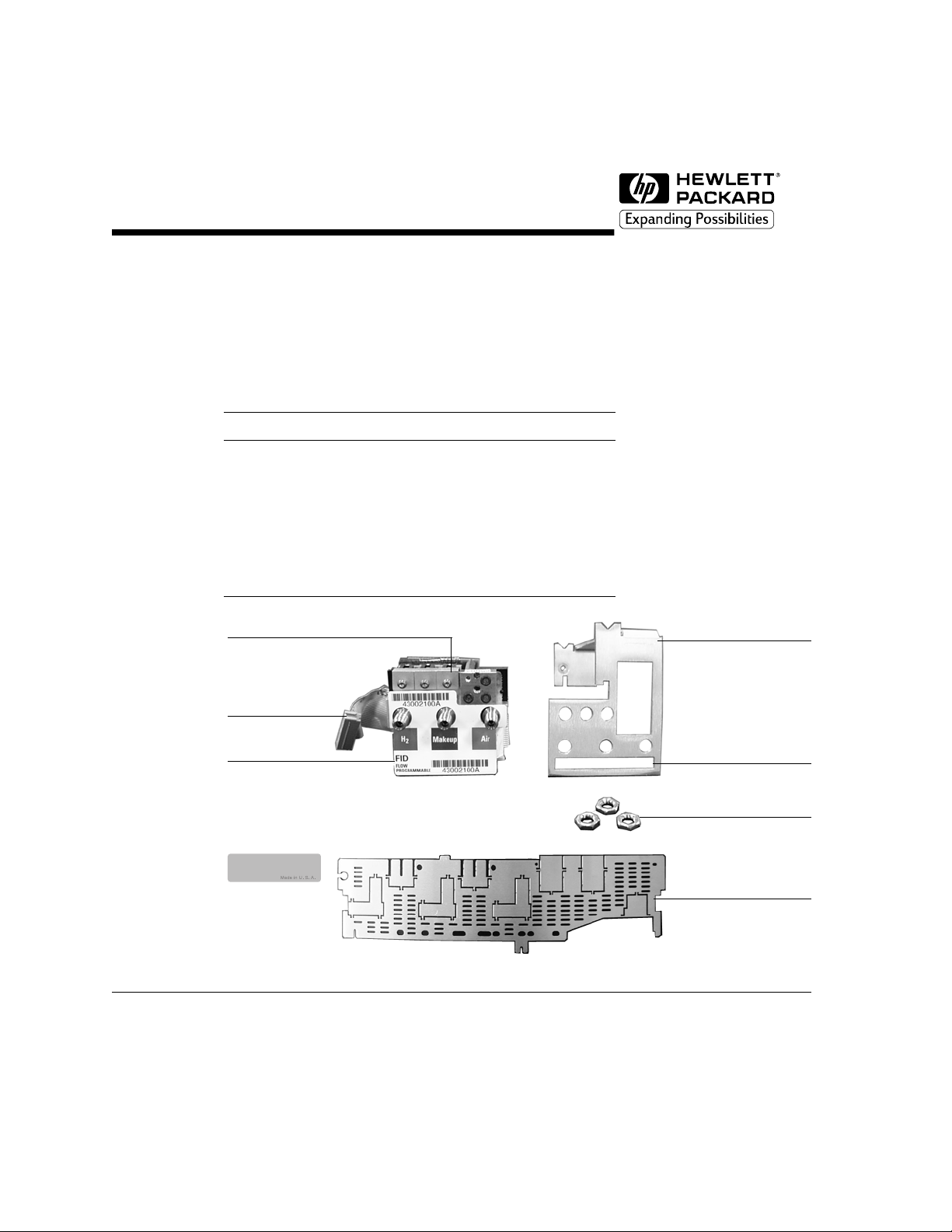
Figure 1 FID EPC flow control manifold replacement kit
Kit G1531-60720 Qty.
FID EPC flow control manifold 1
Mounting bracket, HP 6890 1
Top rear panel 1
Installation sheet (this document) 1
Blank label 1
Hex nut, 7/16 inch 3
HP 6890 mounting bracket
Gang fitting
ID tag
Ribbon cable
Top rear panel
FID EPC flow control manifold
7/16 inch hex nuts
installs here
Slot for label tag
Blank label
2
Tools required
Safety information
Before continuing, read the safety information in your GC Operating Manual.
Removing the existing manifold
WA R NI N G Hydrogen gas is flammable and potentially explosive. Before replacing the
manifold, turn off the hydrogen gas at the source.
WA R NI N G Before proceeding, turn off the oven and any heated zones and let them cool
down. Turn off all detector gases at their supply, then turn off the main power
switch and unplug the power cord.
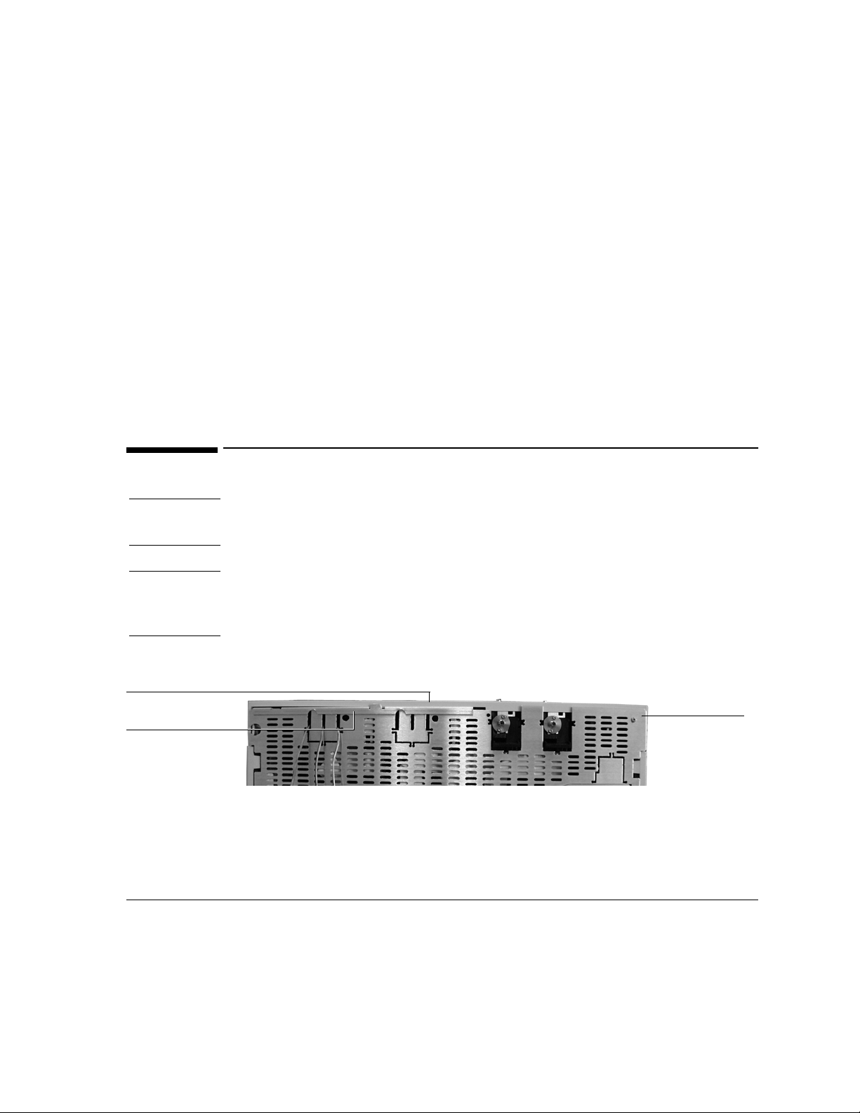
1. Remove the pneumatics cover and the RFI shield under it. See Figure 2.
Figure 2 Back view of HP 6890
7/16 inch open-ended wrench
T-20 Torx driver
Needle-nosed pliers
RFI shield
Pneumatics cover
Top rear panel
3
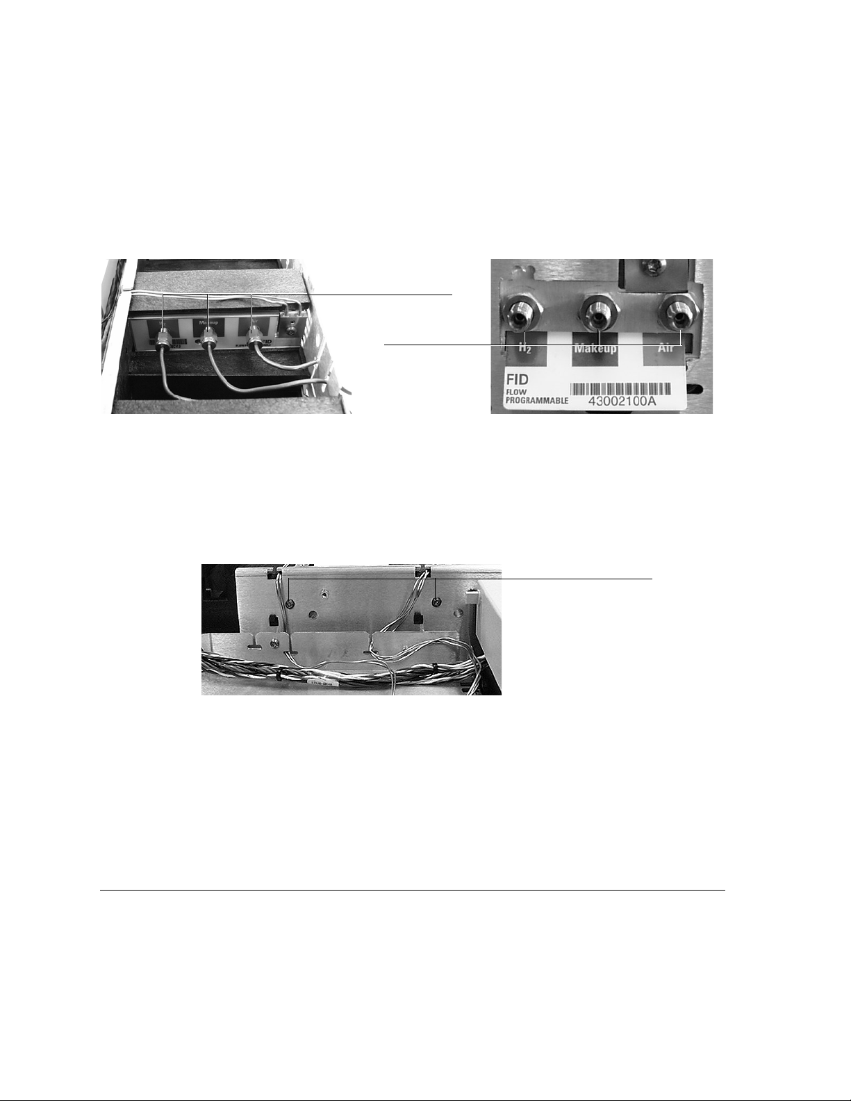
2. Remove the gas supply tubing from the present manifold. See Figure 3.
Figure 3 Remove the gas connections
3. Remove the detector cover and the top rear panel.
4. Remove the Torx T-20 mounting screw from the front of the manifold. See
Figure 4.
Figure 4 Removing the detector flow manifold
5. Disengage the detector tubing from the slots in the chassis so that the gang
fitting on the manifold can be removed easily. See Figure 4.
Manifold, installed before May 1998
Disconnect gas lines
Disconnect gas lines
Manifold, installed after May 1998
OR
Torx T-20 screws
holding detector manifolds
 Loading...