


744
Table of contents
 Loading...
Model 744 Owner’s Guide
This guide contains installation instructions.
HP Part No. A4511-90602
Edition E0897
Printed in U.S.A.

Hewlett-Packard Co. 1997
Printing History
First Printing: September 1996
Latest Printing: August 1997
UNIX is a registered trademark in the United States and other countries,
licensed exclusively through X/Open Company Limited.
NOTICE
The information contained in this document is subject to change without
notice.
HEWLETT-PACKARD MAKES NO WARRANTY OF ANY KIND WITH
REGARD TO THIS MATERIAL INCLUDING BUT NOT LIMITED TO
THE IMPLIED WARRANTIES OF MERCHANTABILITY AND FITNESS FOR A PARTICULAR PURPOSE. Hewlett-Packard shall not be liable for errors contained herein or for incidental or consequential damages in
connection with the furnishing, performance or use of this material.
Hewlett-Packard assumes no responsibility for the use or reliability of its
software on equipment that is not furnished by Hewlett-Packard.
This document contains proprietary information that is protected by copyright. All rights reserved. No part of this document may be photocopied,
reproduced or translated to another language without the prior written consent of Hewlett-Packard Company.
RESTRICTED RIGHTS LEGEND. Use, duplication, or disclosure by government is subject to restrictions as set forth in subdivision (c) (1) (ii) of the
Rights in Technical Data and Computer Software Clause at DFARS
252.227.7013. Hewlett-Packard Co., 3000 Hanover St., Palo Alto, CA
94304.
10 9 8 7 6 5 4 3 2 1

Contents
Preface
Audience Preface-2
Safety and Regulatory Statements Preface-2
Electrostatic Discharge (ESD) Precautions Preface-4
Release Document(s) Preface-4
Related Manuals Preface-5
Revision History Preface-6
Documentation Conventions Preface-7
Questions, Suggestions, or Problems Preface-8
Declaration of Conformity Preface-9
1 Model 744 Board Computer Overview
Product Description 1-3
Installation Overview 1-7
Installation Notes 1-7
iii

Contents
Supported Products 1-8
Accessory Cards 1-8
Typical External Devices 1-9
Conversion and Standard Cables 1-9
Keyboard and Mouse 1-10
Environmental Requirements 1-11
Operating System Overview 1-13
Manuals for System Information 1-14
HP-UX 1-14
HP VUE 1-14
For information on using and configuring the HP VUE interface with HP-UX, see HP
VUE User’s Guide. For information on installing HP VUE, refer to HP VUE Installation
Guide. 1-14
HP CDE 1-14
Online Sources of Information 1-15
iv
Installing HP-UX and HP-RT 1-17
Audio 1-18
2 Installing Accessories
Tools Required and Preliminary Procedures 2-3
Safety Precautions 2-4
Memory 2-5
Preliminary Requirements 2-5
RAM Card Installation 2-5
RAM Card Removal 2-7
GSC Expansion Kit 2-8
Preliminary Requirements 2-8
GSC Expansion Kit Installation 2-8

GSC Mezzanine Cards 2-11
Installing GSC Mezzanine Cards 2-11
Preliminary Requirements 2-11
GSC Mezzanine Card Installation 2-11
Installing an HCRX Graphics Board 2-12
Preliminary Requirements 2-13
HCRX Graphics Board Installation 2-13
PMC Bridge Adapter and Expansion Adapter 2-15
Preliminary Requirements 2-15
PMC Bridge Adapter and Expansion Adapter Installation 2-15
PCMCIA 2-26
3 Typical Installation in a VME Card Cage
Configuring the VME Card Cage 3-3
Contents
Keyboard and Mouse 3-7
Model 744 Installation 3-8
Tools Required 3-8
Preliminary Requirements 3-8
Installing a Single-Slot Model 744 into an HP Card Cage 3-8
Installing a Dual-Slot Model 744 3-9
Non-HP Installation 3-10
HP Installation (Other Than Primary CPU) 3-11
Model 744 Removal 3-12
Tools Required 3-12
Preliminary Requirements 3-12
Removing a Model 744 3-12
v

Contents
4 Connecting Cables
Introduction 4-3
Connecting a Single Monitor, Multi-Display System, or Text-Only Terminal 4-4
Configuration Requirements 4-4
Monitors 4-4
Multi-Display Systems 4-5
Connecting the Monitor 4-5
Power Cord 4-7
Connecting a Terminal 4-7
Audio Connection 4-9
Video Connection 4-12
Keyboard and Mouse Connections 4-13
Network Connection 4-14
vi
Printer Connections 4-16
Preparing for HP-UX Installation 4-16
Configuring HP-UX for a Printer 4-16
Printer Interface 4-16
Printer Cables 4-17
Installation Procedure 4-17
Testing the Printer Installation 4-19
HP Parallel 4-19
RS-232 Port A 4-21
SCSI Connection 4-22
5 Powering On and Off
Turning On the System 5-3
Turning Off the System 5-5

6 Solving Problems
Interpreting the LEDs 6-3
Managing a Boot Failure 6-5
Printer Problems 6-6
A The Boot Console Interface
Boot Console User Interface Features A-2
Main Menu A-3
Configuration Menu A-4
Information Menu A-5
Service Menu A-5
VME Menu A-6
Contents
Accessing the Boot Console Interface A-7
Booting Your Workstation A-9
Searching for Bootable Media A-11
Restoring the Factory Default Configuration A-12
Displaying and Setting Paths A-13
Displaying and Setting the Monitor Type A-16
The Monitor Command A-16
Displaying the Current Monitor Configuration A-17
Setting the Monitor Type A-18
Setting the Monitor Type at Power On A-20
Using the Emergency Interactive Console Search A-21
Displaying the Current Memory Configuration A-23
Memory Information Example A-23
Displaying the Status of the System I/O A-25
vii

Contents
Setting the Auto Boot and Auto Search and Auto Start Flags A-26
Displaying and Setting the Security Mode A-28
Displaying and Setting the Fastboot Mode A-29
Displaying the LAN Station Address A-30
Displaying System Information A-31
Displaying PIM Information A-32
Displaying and Setting VME Backplane Networking Configuration A-33
Displaying and Setting VME Backplane ROM Boot Configuration A-34
Displaying and Setting the VME Chassis Codes Mode Flag A-35
Restoring the Factory Default VME EEPROM Configuration A-36
viii

Figures
Contents
Model 744 Board Computer (Top View) 1-12
Installing RAM Cards 2-7
Installing the GSC Expansion Kit (Exploded View with GSC Card) 2-9
Adding the Front Panel Screws 2-10
Installing a GSC Mezzanine Card (Exploded View with Adapter) 2-12
Installing an HCRX Graphics Board 2-14
Installing a PMC Card onto the PMC Bridge Adapter 2-16
Installing the PMC Bridge Adapter onto the Board Computer 2-17
Installing a PMC Card onto the Expansion Adapter 2-18
Removing Bridge Adapter Screws and EMI Gasket 2-19
Installing the Expansion Adapter onto the Bridge Adapter 2-20
Removing Ejector Handle Labels 2-21
Installing Ejector Handle Sleeves 2-22
Installing the Springs and Labels 2-23
Installing the Board Computer with PMC into VME Card Cage 2-24
Model 744 Memory Slots 3-5
Board Computer Captive Screws 3-9
Board Computer Captive Screws 3-13
Model 744 Front Panel Connectors 4-3
Connecting a Monitor to HCRX, GSC, or On-Board Video Connector 4-6
Connecting a Terminal to the RS-232 Ports 4-7
Audio Connector 4-11
Video Connector 4-12
PS/2 Connector 4-13
AUI LAN Connector 4-14
HP Parallel Connector 4-20
RS-232 Serial Connector 4-21
SCSI Connector 4-22
Model 744 LED Location 6-3
ix

Contents
Tables
Environmental Requirements 1-11
Determining the VME Card Cage Configuration 3-3
Model 744/132L Memory Card Current Usage Worksheet 3-5
Model 744/165L Memory Card Current Usage Worksheet 3-5
Model 744 Current Requirements Worksheet 3-6
Monitor Conversion Cables Required 4-5
Audio Specifications 4-10
Audio Connector Pinouts 4-11
Video Connector Pins and Signals 4-12
PS/2 Connector Pinouts 4-13
AUI LAN Connector Pinouts 4-15
HP Parallel Connector Pinouts 4-20
RS-232-C Connector Pinouts 4-21
SCSI Connector Pinouts 4-23
LED Indicators 6-4
System Paths A-13
Mnemonic Style Notation A-14
x

Preface
This owner’ s guide describes ho w to install and use the HP Model 744 Board
Computer.
Preface-1

Audience
This guide is intended for HP 9000 Model 744 Board Computer users.
Safety and Regulatory Statements
Safety
For safety information see the owner’s guide that came with the system in
which you are installing your Model 744 board computer.
Regulatory Statements
Emissions Regulations
Federal Communications Commission (FCC) This equipment has been
tested and found to comply with the limits for a Class A digital device, pursuant to part 15 of the FCC Rules and interference causing regulations of
Industry Canada. These limits are designed to provide reasonable protection
against harmful interference in a non-residential installation. This equipment
generates, uses, and can radiate radio frequency energy and, if not installed
and used in accordance with the instructions, may cause harmful interference to radio communications. However, there is no guarantee that interference will not occur in a particular installation. If this equipment does cause
harmful interference to radio or television reception (determined by turning
the equipment off and on), you can correct the interference by one or more
of the following measures:
Preface-2
• Reorient or relocate the receiving antenna.
• Increase the separation between the equipment and the receiver.
• Connect the equipment to an outlet on a circuit different from that to which the
receiver is connected.
Hewlett-Packard’s system certification tests were conducted with HP-supported peripheral devices and HP shielded cables, such as those you receive
with your computer. Changes or modifications not expressly approved by
Hewlett-Packard could void the user’s authority to operate the equipment.
Korean Regulations on EMI, 1991V3
Please note that this device has been approved for business purposes with
regard to electromagnetic interference.
VCCI Class A ITE
Preface-3

Electrostatic Discharge (ESD) Precautions
Electrostatic charges can damage the integrated circuits on printed circuit
boards. To prevent such damage from occurring, observe the following precautions during board unpacking, installation, and configuration:
• Stand on a static-free mat.
• Wear a static strap to ensure that any accumulated electrostatic charge is
discharged from your body to ground.
• Connect all equipment together, including the static-free mat, static strap,
routing nodes, and peripheral units.
• Keep uninstalled printed circuit boards in their protective antistatic bags.
• Handle printed circuit boards by their edges, once you have removed them
from their protective antistatic bags.
Release Document(s)
Please refer to the Release Document(s) you received with your system or
system software for additional information that we may not have been able
to include in this guide at the time of its publication.
Preface-4

Related Manuals
If you are using HP-UX version 10.20, refer to the following manuals for
more information:
• Model 748 Owner’s Guide (A4511-90604)
• Using Your HP Workstation (A2615-90003)
• Installing and Updating HP-UX (B2355-90050)
• Graphics Administration Guide (B2355-90109)
• Configuring HP-UX for Peripherals (B2355-90053)
• HP Visual User Environment User’s Guide (B1171-90079)
• Managing Clusters of HP 9000 Computers: Sharing the HP-UX
File System (B2355-90038)
• HP-UX X User Environment User’s Guide
If you are using HP-RT, refer to the following manuals for more information:
• Application Programming in the HP-RT Environment
• Driver Writing in the HP-RT Environment
• ELOG Library Programer’s Guide
• HP Z5117A PCMCIA Adapter Installation and User’s Guide
• HP-RT Reference
• HP-RT Quick Reference
• HP-RT System Administration Tasks
• VME Backplane Networking Administration Guide
• X11 SERVERrt Installation and Configuration Guide
• Using SNMP in the HP-RT Environment
• Using STREAMS in the HP-RT Environment
To order manuals, please contact your local sales office.
Preface-5

Revision History
The revision history for each edition of the manual is listed below:
HP Part No. Edition Revision History
A4500-90607 E0996 First printing
A4511-90602 E0897 Updated to include Model
744/165L, PMC, and
memory enhancements
Preface-6

Documentation Conventions
Unless otherwise noted in the text, this guide uses the following symbolic
conventions.
user-supplied values Italic words or characters in for-
mats and command descriptions
represent values that you must
supply.
sample user input In examples, information that the
user enters appears in color.
output
Information that the system displays appears in
face.
this type-
literal values Bold words or characters in for-
mats and command descriptions
represent commands or keywords
that you must use literally. Pathnames are also in bold.
KEY Text with a line above and a line
below denotes a key on your keyboard, or a key or button which is
drawn on your workstation’s
graphic display.
(In this manual we refer to the
Enter key. On your keyboard the
key may be labeled either Enter
or Return.)
Preface-7

Questions, Suggestions, or Problems
If you have any questions, suggestions, or problems with our hardware, software, or documentation, please contact your HP Response Center.
Preface-8
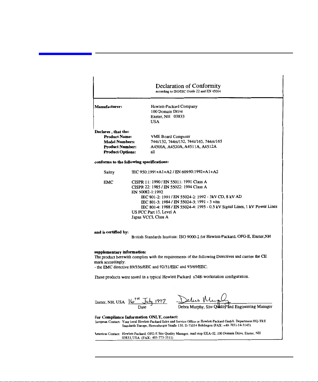
Declaration of Conformity
Preface-9

Preface-10

Preface-11

Preface-12

1
Model 744 Board Computer Overview
1-1

Model 744 Board Computer Overview
This chapter introduces the Model 744 Board Computer. Its purpose is to
familiarize you with the board computer and its installation procedure.
The instructions in this chapter assume you are using either the HP-UX or
HP-RT operating system.
The major sections within this chapter are:
• Product Description
• Installation Overview
• Supported Products
• Environmental Requirements
• Operating System Overview
• Manuals for System Information
• Online Sources of Information
1-2
• Installing HP-UX and HP-RT
• Audio

Model 744 Board Computer Overview
Product Description
Product Description
The HP 9000 Model 744 is a high-performance Precision Architecture board
computer based on the Hewlett-Packard PA-RISC 7300LC technology. It
contains the following key features:
• Model types (the rt designates models that operate under the HP-RT
operating system - the models are physically the same):
Model 744/132L
Model 744rt/132L
Model 744/165L
Model 744rt/165L
• VME slot configuration
Single slot
Dual slot (requires PCI Mezzanine Card (PMC) bridge board, General System Connect (GSC) expansion kit or HCRX graphics
board)
Three slots (requires PMC bridge and expander boards)
• CPU PA-RISC PA7300-LC, processor performance
Model 744/132L - 132 MHz
Primary internal cache - 128 KB: 64 KB instruction, 64KB data
Model 744/165L - 165 MHz
Primary internal cache - 128 KB: 64 KB instruction, 64KB data
Secondary cache - 512 KB
• Clocks
Battery-backed real-time clock
Interval timers (One 32 bit, Two16 bit)
Watchdog timer
1-3

Model 744 Board Computer Overview
Product Description
• Operating systems
HP-UX 10.20 (or later). The Model 744 typically boots from a hard
disk drive. HP-UX may also be installed from an external DDS or
CD-ROM drive.
If the Model 744 is a client on a LAN, HP-UX can be booted over
the LAN.
HP-RT 2.21 (or later).
• User interface
CDE or HP VUE graphical user interface (HP-UX only).
• Compatibility
Source and binary code compatible with Series 700 product family.
• Monitors
Single or multiple display depending on number of installed
graphics options (on-board and/or external).
1-4
Color monitors:
HP A4490D, 17-inch, resolution 1280 x 1024
HP A4331D, 20-inch, resolution 1280 x 1024
Terminal (text only) connected to RS-232 port.
• Optional Graphics Capability
Graphics chip set providing on-board (including accelerated I/O)
graphics.
GSC Expansion kit provides two slots for 3x5 GSC HP A4267A
8-plane graphic cards.
HCRX8 or HCRX24 graphics boards allow the choice of one
HP A4267A graphics card in addition to the graphics board itself.
HP-RT supports an expansion kit with an HP A4267A graphics
card when on-board graphics is not used.

Model 744 Board Computer Overview
Product Description
NOTE: Either a GSC expansion kit or the HCRX expansion graphics boards extend
graphics capability beyond the on-board graphics chip set of a Model 744
Board Computer. However, the HP-RT operating system supports only one
graphics display, and HP-UX 10.x supports up to three graphics displays.
• Main Memory
Single VME slot 744: 32, 64, or 128 MB RAM
Single VME slot 744 with HP-RT: 16 to 128 MB RAM
Dual VME slot 744: 32 to 512 MB RAM
Dual VME slot 744 with HP-RT operating system: 16 to 512 MB
RAM (Dual slot means an expansion kit or HCRX board must be
installed.)
NOTE: A Model 744 configured for more than one RAM card requires installation of
a PMC bridge board, a GSC expansion kit, or an HCRX graphics board,
thereby occupying two VME slots.
Up to four RAM cards may be installed.
When mixing memory card capacities that include 128MB cards,
the 128MB card(s) must be installed into the lowest memory slots
before adding cards of other capacities.
• Standard Features
Internal SCSI-2 single-ended bus
2 asynchronous RS-232-C ports (requires a conversion cable)
1 HP parallel port (requires a conversion cable)
1 LAN AUI port (requires a conversion cable)
2 mini-DIN PS/2 ports
1 slot for RAM memory (memory cards can be stacked)
CD-quality audio, supported only by HP-UX and requires a
conversion cable
PCMCIA adapter, supported only by HP-RT (not supported on
Model 744 with on-board graphics)
1-5

Model 744 Board Computer Overview
Product Description
• Dual Slot Upgrades
PMC bridge board (with two PMC sites, cannot be used w/HCRX,
and supported only on HP-UX)
GSC Expansion kit (with two GSC sites)
HCRX8 graphics board (with one additional GSC site)
HCRX24 graphics board (with one additional GSC site)
3 x 5 GSC HP A4267A graphics card
3 x 5 FWD SCSI card, supported only by HP-UX
• 3-slot Upgrade
PMC Expander board (with two PMC sites, requires PMC bridge)
ATM Network Card (up to 2, GSC expansion kit required, cannot
be used with HCRX graphics)
1-6

Model 744 Board Computer Overview
Installation Overview
Installation Overview
Chapter 2 provides step-by-step instructions for attaching and installing
accessories in a typical VME card cage, and connecting external devices.
Accessories are products that attach to the computer’s system board. They
must be attached before installing the board computer in a VME card cage.
Devices are products used externally to the board computer. Examples are
keyboards, monitors, and mass storage devices. Other de vices are connected
through cables. Depending on your specific application, you may need one
or more accessory and device products. Installation instructions for most
products used directly with your Model 744 Board Computer are explained
in this manual.
Chapter 3 presents the installation tasks required to install and configure
your board computer.
Installation Notes
Your Model 744 Board Computer uses micro-miniature connectors for several interface ports. Cable connectors for these ports are very small, but may
be positioned so that a slight angle exists between them. This situation has
been tested by HP and full functionality is maintained.
CAUTION: The Model 744 Board Computer’s P2 connector has a local bus on the user-
defined pins. Verify that your VME card cage’s backplane makes no
connections to J2/P2, rows A and C. Refer to IEEE STD 1014-1987, Chapter
7, for more information on use of user-defined pins in VME backplane
connectors.
1-7

Model 744 Board Computer Overview
Supported Products
Supported Products
Only products with Hewlett-Packard approved parts, accessories, peripherals, operating systems, and application programs are supported by HewlettPackard. Any product with other than HP approved hardware or software
connected or installed must have the non-HP approved hardware and software removed by the customer before on-site repair is conducted. The following lists describe the products supported by HP.
Accessory Cards
The Model 744 supports the following accessory cards:
• HP A4219A expansion kit
• Memory; one or more of the following RAM cards is supported on
either the HP-UX or HP-RT operating system:
HP A4501A 16 MB RAM card (HP-RT only)
HP A4502A 32 MB RAM card
HP A4503A 64 MB RAM card
HP A4449A 128 MB RAM card
NOTE: HP-UX requires a minimum of 32 MB RAM. HP-RT requires a minimum of
16 MB RAM.
• Mezzanine (GSC expansion kit) cards:
HP A4267A 8-plane color graphics card
HP A4268A FWD SCSI (supported only by HP-UX)
HP J3420A ATM Network Card (supported only by HP-UX)
• PCMCIA (supported only by HP-RT)
• Sub-Mezzanine Cards:
HCXR8 graphics card
HCRX24 graphics card
1-8
Loading...