


 Loading...
Maintenance & Service Guide
HP EliteOne 800 G4 23-inch All-in-One Business PC HP EliteOne 800 G4 23-inch Healthcare Edition All-in- One Business PC
© Copyright 2018 HP Development Company,
L.P.
AMD is a trademark of Advanced Micro Devices, Inc. Bluetooth is a trademark owned by its proprietor and used by HP Inc. under license. Intel, Celeron, and Pentium are trademarks of Intel Corporation in the U.S. and other countries. Microsoft and Windows are trademarks of the Microsoft group of companies.
The information contained herein is subject to change without notice. The only warranties for HP products and services are set forth in the express warranty statements accompanying such products and services. Nothing herein should be construed as constituting an additional warranty. HP shall not be liable for technical or editorial errors or omissions contained herein.
First Edition: June 2018
Document Part Number: L23953-001
Product notice
This user guide describes features that are common to most models. Some features may not be available on your computer.
Not all features are available in all editions of Windows. This computer may require upgraded and/or separately purchased hardware, drivers and/or software to take full advantage of Windows functionality. Go to http://www.microsoft.com for details.
Software terms
By installing, copying, downloading, or otherwise using any software product preinstalled on this computer, you agree to be bound by the terms of the HP End User License Agreement (EULA). If you do not accept these license terms, your sole remedy is to return the entire unused product (hardware and software) within 14 days for a full refund subject to the refund policy of your seller.
For any further information or to request a full refund of the price of the computer, please contact your seller.

About This Book
 WARNING! Text set o in this manner indicates that failure to follow directions could result in bodily harm or loss of life.
 CAUTION: Text set o in this manner indicates that failure to follow directions could result in damage to equipment or loss of information.
 NOTE: Text set o in this manner provides important supplemental information.
iii
iv About This Book

Table of contents
1 Product features ........................................................................................................................................... |
1 |
Overview ................................................................................................................................................................ |
1 |
HP EliteOne 800 G4 front components .................................................................................................................. |
1 |
HP EliteOne 800 G4 Healthcare front components ............................................................................................... |
2 |
Top components .................................................................................................................................................... |
2 |
Infrared (IR) webcam (optional) .......................................................................................................... |
2 |
Full High De nition (FHD) webcam (optional) ..................................................................................... |
3 |
Side components ................................................................................................................................................... |
3 |
Rear components ................................................................................................................................................... |
4 |
Bottom components .............................................................................................................................................. |
4 |
Labels ..................................................................................................................................................................... |
5 |
2 Illustrated parts catalog ................................................................................................................................ |
6 |
System parts .......................................................................................................................................................... |
6 |
Misc plastic parts ................................................................................................................................................... |
7 |
Boards .................................................................................................................................................................... |
8 |
Mass storage devices ............................................................................................................................................. |
9 |
Processors and memory modules ....................................................................................................................... |
10 |
Cables and adapters ............................................................................................................................................ |
10 |
Keyboards and mice ............................................................................................................................................. |
11 |
3 Routine care, SATA drive guidelines, and disassembly preparation .................................................................. |
12 |
Operating guidelines and routine care ................................................................................................................ |
12 |
Service considerations ......................................................................................................................................... |
13 |
Tools and software requirements ..................................................................................................... |
13 |
Screws ............................................................................................................................................... |
14 |
Cables and connectors ...................................................................................................................... |
14 |
Hard drives ........................................................................................................................................ |
14 |
Lithium coin cell battery .................................................................................................................... |
14 |
Electrostatic discharge information .................................................................................................................... |
15 |
Generating static ............................................................................................................................... |
15 |
Preventing electrostatic damage to equipment ............................................................................... |
15 |
Personal grounding methods and equipment .................................................................................. |
16 |
Grounding the work area ................................................................................................................... |
16 |
Recommended materials and equipment ........................................................................................ |
16 |
Cable management .............................................................................................................................................. |
17 |
v
4 Removal and Replacement Procedures .......................................................................................................... |
18 |
Preparing to disassemble the computer ............................................................................................................. |
18 |
Removing the rear port cover .............................................................................................................................. |
18 |
Stands .................................................................................................................................................................. |
19 |
Recline stand ..................................................................................................................................... |
19 |
Adjustable height stand .................................................................................................................... |
19 |
Access panel ......................................................................................................................................................... |
20 |
Locating internal components ............................................................................................................................ |
21 |
Hard drive ............................................................................................................................................................. |
22 |
Optical drive ......................................................................................................................................................... |
23 |
M.2 solid-state drive ............................................................................................................................................ |
25 |
Memory ................................................................................................................................................................ |
26 |
Battery ................................................................................................................................................................. |
28 |
WLAN module ...................................................................................................................................................... |
29 |
Power button and ngerprint reader boards ...................................................................................................... |
30 |
RFID board ............................................................................................................................................................ |
32 |
Heat sink .............................................................................................................................................................. |
33 |
Processor ............................................................................................................................................................. |
34 |
Webcam module .................................................................................................................................................. |
35 |
VESA mounting bracket/fan assembly ................................................................................................................ |
38 |
Power supply ....................................................................................................................................................... |
40 |
Rear I/O cover ....................................................................................................................................................... |
42 |
I/O bracket ............................................................................................................................................................ |
43 |
Hard drive cage .................................................................................................................................................... |
44 |
System board ....................................................................................................................................................... |
45 |
System board callouts ......................................................................................................................................... |
48 |
Audio board .......................................................................................................................................................... |
49 |
Speakers .............................................................................................................................................................. |
50 |
Display panel ....................................................................................................................................................... |
51 |
Antennas .............................................................................................................................................................. |
54 |
5 Computer Setup (F10) Utility ........................................................................................................................ |
56 |
Computer Setup (F10) Utilities ............................................................................................................................ |
56 |
Using Computer Setup (F10) Utilities ................................................................................................ |
56 |
Computer Setup–Main ....................................................................................................................... |
58 |
Computer Setup—Security ............................................................................................................... |
60 |
Computer Setup—Advanced ............................................................................................................. |
64 |
Recovering the con guration settings ................................................................................................................ |
69 |
vi
6 Using HP PC Hardware Diagnostics ................................................................................................................ |
70 |
Using HP PC Hardware Diagnostics Windows (select products only) ................................................................. |
70 |
Downloading HP PC Hardware Diagnostics Windows ....................................................................... |
70 |
Downloading the latest HP PC Hardware Diagnostics Windows version ....................... |
71 |
Downloading HP Hardware Diagnostics Windows by product name or number |
|
(select products only) ..................................................................................................... |
71 |
Installing HP PC Hardware Diagnostics Windows ............................................................................. |
71 |
Using HP PC Hardware Diagnostics UEFI ............................................................................................................. |
71 |
Starting HP PC Hardware Diagnostics UEFI ....................................................................................... |
72 |
Downloading HP PC Hardware Diagnostics UEFI to a USB flash drive .............................................. |
72 |
Downloading the latest HP PC Hardware Diagnostics UEFI version .............................. |
72 |
Downloading HP PC Hardware Diagnostics UEFI by product name or number |
|
(select products only) ..................................................................................................... |
72 |
Using Remote HP PC Hardware Diagnostics UEFI settings (select products only) ............................................. |
73 |
Downloading Remote HP PC Hardware Diagnostics UEFI ................................................................. |
73 |
Downloading the latest Remote HP PC Hardware Diagnostics UEFI version ................. |
73 |
Downloading Remote HP PC Hardware Diagnostics UEFI by product name or |
|
number ............................................................................................................................ |
73 |
Customizing Remote HP PC Hardware Diagnostics UEFI settings .................................................... |
73 |
7 Troubleshooting without diagnostics ............................................................................................................ |
75 |
Safety and comfort .............................................................................................................................................. |
75 |
Before you call for technical support .................................................................................................................. |
75 |
Helpful hints ........................................................................................................................................................ |
76 |
Solving general problems .................................................................................................................................... |
77 |
Solving power problems ...................................................................................................................................... |
80 |
Solving hard drive problems ................................................................................................................................ |
81 |
Solving audio problems ....................................................................................................................................... |
83 |
Solving printer problems ..................................................................................................................................... |
84 |
Solving keyboard and mouse problems .............................................................................................................. |
85 |
Solving hardware installation problems ............................................................................................................. |
86 |
Solving network problems .................................................................................................................................. |
87 |
Solving memory problems .................................................................................................................................. |
89 |
Solving USB flash drive problems ........................................................................................................................ |
91 |
Solving Internet access problems ....................................................................................................................... |
91 |
Solving software problems .................................................................................................................................. |
92 |
8 Backing up, restoring, and recovering ........................................................................................................... |
94 |
Using Windows tools ........................................................................................................................................... |
94 |
Creating HP Recovery media (select products only) ........................................................................................... |
94 |
Using HP Recovery Manager to create recovery media .................................................................... |
95 |
vii
Before you begin ............................................................................................................. |
95 |
Creating the recovery media ........................................................................................... |
95 |
Using the HP Cloud Recovery Download Tool to create recovery media .......................................... |
96 |
Restoring and recovery ........................................................................................................................................ |
96 |
Restoring, resetting, and refreshing using Windows tools .............................................................. |
96 |
Restoring using HP Recovery Manager and the HP Recovery partition ........................................... |
96 |
Recovering using HP Recovery Manager ........................................................................................... |
96 |
Recovering using the HP Recovery partition (select products only) ................................................ |
97 |
Recovering using HP Recovery media ............................................................................................... |
97 |
Changing the computer boot order ................................................................................................... |
98 |
Removing the HP Recovery partition (select products only) ............................................................ |
98 |
9 POST error messages and diagnostic front panel LEDs and audible codes ......................................................... |
99 |
POST numeric codes and text messages ............................................................................................................. |
99 |
Interpreting system validation diagnostic front panel LEDs and audible codes .............................................. |
104 |
10 Password security and resetting CMOS ...................................................................................................... |
106 |
Resetting the password jumper ........................................................................................................................ |
106 |
Clearing and resetting the BIOS ........................................................................................................................ |
108 |
Appendix A Power cord set requirements ....................................................................................................... |
109 |
General requirements ........................................................................................................................................ |
109 |
Japanese power cord requirements .................................................................................................................. |
109 |
Country-speci c requirements .......................................................................................................................... |
110 |
Appendix B Statement of memory volatility ................................................................................................... |
111 |
Nonvolatile memory usage ............................................................................................................................... |
113 |
Questions and answers ..................................................................................................................................... |
115 |
Using HP Sure Start (select models only) .......................................................................................................... |
116 |
Appendix C peci c tions ............................................................................................................................. |
117 |
Index ........................................................................................................................................................... |
118 |
viii
1Product features
Overview
 NOTE: For the latest manuals on this product, go to http://www.hp.com/support. Select Find your product, and then follow the on-screen instructions.
This product employs electronic labeling for indication of regulatory mark or statement. See Labels on page 5 for the operation to display.
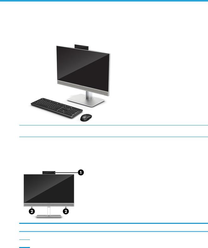
HP EliteOne 800 G4 front components
Component
1Webcam
2Speakers (select products only)
Overview 1
HP EliteOne 800 G4 Healthcare front components
Component |
Component |
||
|
|
|
|
1 |
Webcam |
3 |
Speakers (2) |
|
|
|
|
2 |
Fingerprint reader (select products only) |
4 |
Radio Frequency identi cation (RFID) tapping area and |
|
|
|
antenna* (select models only) |
*The antenna is not visible from the outside of the computer. For optimal transmission, keep the area immediately around the antenna free from obstructions.
For wireless regulatory notices, see the section of the Regulatory, Safety, and Environmental Notices that applies to your country or region.
To access this guide:
▲Select the Start button, select HP Help and Support, and then select HP Documentation.
‒ or –
▲Select the Start button, select HP, and then select HP Documentation.
Top components
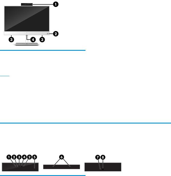
Infrared (IR) webcam (optional)
|
Component |
|
Component |
|
|
|
|
|
|
Front View |
|
|
|
|
|
1 |
Webcam light |
4 |
IR webcam |
|
|
|
|
2 |
IR light |
5 |
Rear webcam adjustment wheel |
|
|
|
|
3 |
Full High De nition (FHD) webcam |
|
|
|
|
|
|
|
|
Top view |
|
|
|
|
|
6 |
Digital microphones |
|
|
|
|
|
|
|
|
Rear view |
|
|
|
|
|
7 |
Webcam light |
8 |
FHD webcam |
|
|
|
|
2Chapter 1 Product features
Full High De nition (FHD) webcam (optional)
Component
Front view
1 Webcam light
2FHD webcam
Top view
3Digital microphones
Side components
Component |
Component |
||
|
|
|
|
1 |
Optical disc drive (optional) |
4 |
Audio-out (headphone)/Audio-in (microphone) combo jack |
|
|
|
|
2 |
Optical disc drive light (select products only) |
5 |
Audio-out (headphone) jack |
|
|
|
|
3 |
Optical disc drive eject button (optional) |
6 |
Fingerprint reader (select products only) |
|
|
|
|
Side components |
3 |
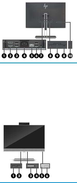
Rear components
Component |
Component |
||
|
|
|
|
1 |
DisplayPort |
6 |
USB 3.1 Type-A ports (2) |
|
|
|
|
2 |
HDMI port |
7 |
Stereo audio-out jack |
|
|
|
|
3 |
USB 3.1 Type-A ports (2) |
8 |
Security lock screws |
|
|
|
|
4 |
Power connector |
9 |
Stand release |
|
|
|
|
5 |
RJ-45 (network) jack |
10 |
Security cable slot |
|
|
|
|
Bottom components
Component |
Component |
||
|
|
|
|
1 |
USB 3.1 Type-A port |
4 |
USB 3.1 Type-C port |
|
|
|
|
2 |
USB 3.1 Type-A (charging) port |
5 |
Hard drive activity light |
|
|
|
|
3 |
SD card reader |
6 |
Power button |
|
|
|
|
4Chapter 1 Product features
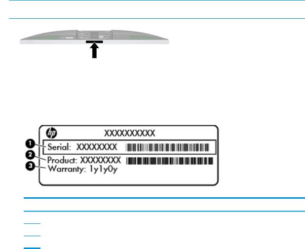
Labels
The labels affixed to the computer provide information you may need when you troubleshoot system problems or travel internationally with the computer.
 IMPORTANT: All labels described in this section will be located under the stand or affixed to the bottom of the computer.
1.Microsoft® Certi cate of Authenticity label. Contains the Windows Product Key. You may need the Product Key to update or troubleshoot the operating system.
2.Service label—Provides important information to identify your computer. When contacting support, you will probably be asked for the serial number, and possibly for the product number or the model number. Locate these numbers before you contact support.
Component
(1)Serial number
(2)Product number
(3)Warranty period
3.Serial number label
Labels 5
2Illustrated parts catalog
Component appearance may vary depending on model.
 NOTE: HP continually improves and changes product parts. For complete and current information on supported parts for your computer, go to http://partsurfer.hp.com, select your country or region, and then follow the on-screen instructions.
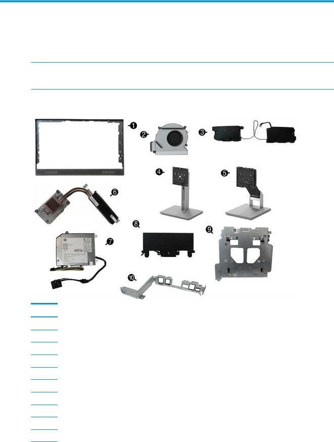
System parts
Item Description
(1) |
Middle frame (heatthcare models and standard models use di erent spare part kits) |
(2)Blower (Fan)
(3)Speakers (heatthcare models and standard models use di erent spare part kits)
(4)Adjustable Height Stand
(5)Recline Stand
(6)Heat sink
(7)Power supply, 180 W
(8)Camera, pop-up (HD and IR)
(9)VESA/fan bracket
(10)I/O bracket
6Chapter 2 Illustrated parts catalog
Item Description
*
*
I/O holder (for use in healthcare models)
I/O door (for use in healthcare models)
*Display cable
*Display panel kit
Non-touch for use in healthcare models Non-touch with RFID for use in healthcare models Non-touch for use in non-healthcare models Touch for use in non-healthcare models
* not illustrated
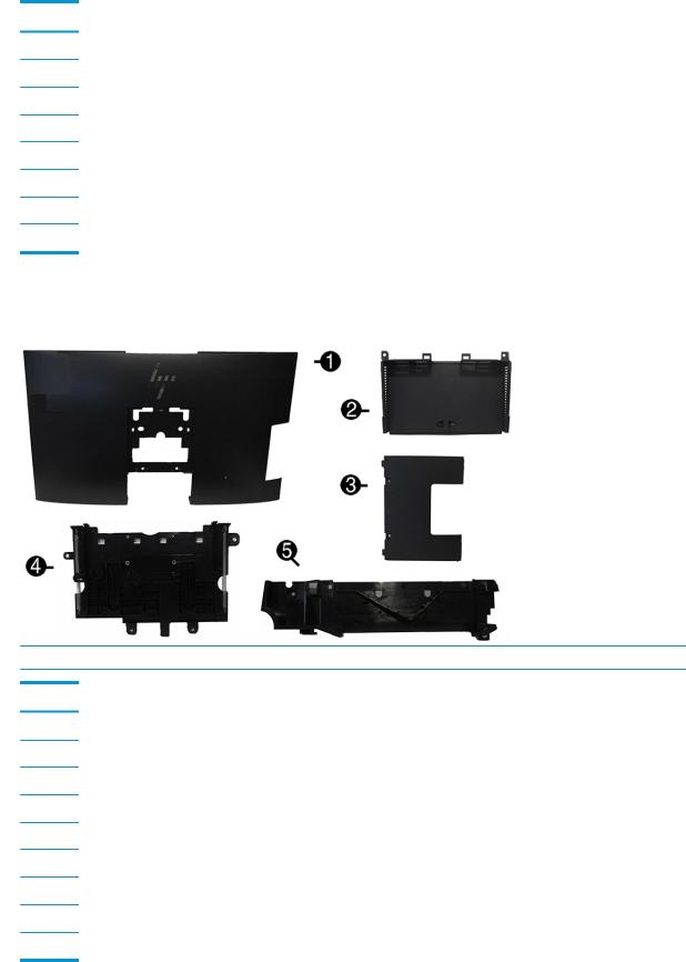
Misc plastic parts
 NOTE: Healthcare models exterior plastic parts are white.
Item Description
(1)Rear cover (main)
(2)Rear I/O cover
(3)Rear port cover
(4)Webcam holder (located under the webcam)
(5)Webcam cover
*
*
*
Optical drive cover (for use in models without an optical drive)
Card reader cover (for use in models without a card reader)
VESA cover (for use in models with out a stand)
*Optical drive bezel
* not illustrated
Misc plastic parts |
7 |
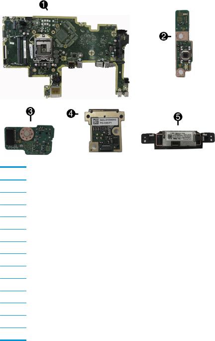
Boards
Item Description
(1)System board
(2)Power button board
(3)Audio board
(4)Fingerprint reader board (available only for non-healthcare models)
(5)RFID module (available only for healthcare models)
(5)RFID holder (available only for healthcare models)
*Fingerprint scanner (available only for healthcare models)
*Fingerprint scanner frame (available only for healthcare models)
*WLAN modules (not illustrated)
Intel Dual Band Wireless-AC 9560 802.11 AC 2x2 WiFi + Bluetooth 5.0 Combo Adapter (vPro) Intel Dual Band Wireless-AC 9560 802.11 AC 2x2 WiFi + Bluetooth 5.0 Combo Adapter (non-vPro) Realtek RTL8821CE 802.11 ac 1x1 WiFi + BT 4.2 Combo Adapter (MU-MIMO supported)
Realtek RTL8822BE 802.11 ac 2x2 WiFi + BT 4.2 Combo Adapter (MU-MIMO supported)
* not illustrated
8Chapter 2 Illustrated parts catalog

Mass storage devices
Description
Optical drive
DVD Blu-ray-writer
DVD±RW drive
DVD-ROM drive
Hard drive, 2.5-inch
2 TB, 5400 rpm
1 TB, 5400 rpm, hard drive/hybrid SSD drive
1 TB, 7200 rpm
500 GB, 5400 rpm
500 GB, 5400 rpm, hard drive/hybrid SSD drive
500 GB, 7200 rpm hard drive, self-encrypting (SED)
500 GB, 7200 rpm hard drive
500 GB, 5400 rpm hard drive, FIPS
Solid-state drive, SATA-3, 2.5-inch
512-GB solid-state drive, FIPS 140-2
512-GB solid-state drive, self-encrypting (SED)
256-GB solid-state drive, self-encrypting (SED)
256-GB solid-state drive
256-GB solid-state drive, FIPS 140-2
256-GB solid-state drive, TLC
M.2 solid-state drive (NVMe, PCIe)
1-TB solid-state drive, TLC
512-GB solid-state drive, TLC
512-GB solid-state drive
256-GB solid-state drive, TLC
128-GB solid-state drive, TLC
128-GB solid-state drive
Optane memory module, 16 GB
Mass storage devices |
9 |

Processors and memory modules
Description
Intel Processors (include replacement thermal material)
Intel Core i7-8700 (3.6-GHz)
Intel Core i5-8600 (3.5-GHz)
Intel Core i5-8500 (3.4-GHz)
Intel Core i3-8033 (4.1-GHz)
Intel Core i3-8011 (4.0-GHz)
Intel Pentium G5600 (3.7-GHz)
Intel Pentium G5500 (3.6-GHz)
Intel Pentium G5400 (3.5-GHz)
Intel Celeron G4900 (3.0-GHz)
Memory modules (SODIMM; DDR4-2666)
16-GB
8-GB
4-GB
Cables and adapters
Description
Power button singe and combination cables
Single cable for power board only for healthcare models without FIPS
Combo cable for power board and FIPS for healthcare models with FIPS
Combo cable for power board, touch panel, and swipe ngerprint reader for touch models
Combo cable for power board and swipe ngerprint reader for non-touch models
RFID cable (for use only in healthcare models)
Side audio jack cable
AIT touch cable
LVDS (display) cable
Backlight cables
AIO
LGD
INX
SDC
DisplayPort cable, 1.8 m
10 Chapter 2 Illustrated parts catalog

Description
Antennas (wireless, for use with WLAN modules)
USB-C to USB-A hub
Adapters
DisplayPort to DVI
DisplayPort to HDMI 2.0
DisplayPort to VGA
USB to serial port
USB-C to USB 3.0
USB to serial
Keyboards and mice
Description
Keyboard
USB, slim
Wireless with mouse
USB business slim, grey
USB business slim, antimicrobial
Mouse
USB, washable
USB, grey
USB, hardened
USB, antimicrobial
USB, optical
USB, laser
Keyboards and mice 11

3Routine care, SATA drive guidelines, and disassembly preparation
This chapter provides general service information for the computer. Adherence to the procedures and precautions described in this chapter is essential for proper service.
 CAUTION: When the computer is plugged into an AC power source, voltage is always applied to the system board. You must disconnect the power cord from the power source before opening the computer to prevent system board or component damage.
Operating guidelines and routine care
Follow these guidelines to properly set up and care for the computer and monitor:
●Keep the computer away from excessive moisture, direct sunlight, and extremes of heat and cold.
●Operate the computer on a sturdy, level surface. Leave a 10.2 cm (4 in) clearance on all vented sides of the computer and above the monitor to permit the required airflow.
●Never restrict the airflow into the computer by blocking any vents or air intakes. Do not place the keyboard, with the keyboard feet down, directly against the front of the desktop unit as this also restricts airflow.
●Never operate the computer with any of the access panels or any of the expansion card slot covers removed.
●Do not stack computers or place computers so near each other that they are subject to each other’s recirculated or preheated air.
●If the computer is to be operated within a separate enclosure, intake and exhaust ventilation must be provided on the enclosure, and the same operating guidelines listed above will still apply.
●Keep liquids away from the computer and keyboard.
●Never cover the ventilation slots with any type of material.
●Install or enable power management functions of the operating system or other software, including sleep states.
● |
To clean the computer, rst turn o the computer. |
|
|
– |
Disconnect AC power. |
|
– |
Disconnect all powered external devices. |
|
– |
Occasionally clean the air vents on all vented sides of the computer. Lint, dust, and other foreign |
|
|
matter can block the vents and limit the airflow. |
|
– |
In addition to the standard care guidelines, to clean the healthcare model, use ready-to-use |
|
|
cleaning wipes that contain any of the following chemical solutions. Start with the display and |
|
|
nish with any flexible cables. Allow the computer to air-dry before use. |
 IMPORTANT: Spray the cleaner onto a cloth and use the damp cloth to gently wipe the screen surface. Never spray the cleaner directly on the screen surface. It may run behind the bezel and damage the electronics.
12 Chapter 3 Routine care, SATA drive guidelines, and disassembly preparation
IMPORTANT: Do not use cleaners that contain any petroleum based materials such as benzene, thinner, or any volatile substance to clean the display screen or cabinet. These chemicals may damage the display.
Recommended cleaning formulas
Benzyl-C12–18–alkyldimethyl ammonium chlorides: <0.1%, quaternary ammonium compounds, C12–14– alkyl[(ethylphenyl)methyl]dimethyl, chlorides: <0.1%
Isopropanol: 10–20%, benzyl-C12–18–alkyldimethyl ammonium chlorides: <0.5%, quaternary ammonium compounds, C12–18–alkyl[(ethylphenyl)methyl]dimethyl, chlorides: <0.5%
Quaternary ammonium compounds, C12–18–alkyl[(ethylphenyl)methyl]dimethyl, chlorides: <0.5%, benzyl-C12–18– alkyldimethyl ammonium chlorides: <0.5%
Isopropyl alcohol: 55%, alkyl dimethyl benzyl ammonium chlorides: 0.25%, alkyl (68% C12, 32% C14) dimethyl ethylbenzyl ammonium chloride: 0.25%
Isopropanol: 10–20%, ethylene glycol monobutyl ether (2–butoxyethanol): 1–5%, diisobutylphenoxyethoxyethyl dimethyl benzyl ammonium chloride: 0.1–0.5%
Sodium hypochlorite 0.1–1%
Cellulose: 10–30%, ethyl alcohol: 0.1–1%
Isopropanol: 30–40%, water 60–70%
 NOTE: Contact your local HP sales representative for recommended brands of ready-to-use cleaning wipes which have been tested for cleaning the display.
 WARNING!
●Using cleaning methods or disinfectants that are not approved could damage the device.
●Do not immerse the device in liquid.
●Always follow the instructions provided by the cleaning product manufacturer.
●Do not use petroleum-based cleaning fluids, such as acetone.
●Do not use abrasive cleaning aids or products.
●Do not expose the device to temperatures above 70° C.
Service considerations
Listed below are some of the considerations that you should keep in mind during the disassembly and assembly of the computer.
Tools and software requirements
To service the computer, you need the following:
●Torx T-15 screwdriver
●Torx T-15 screwdriver with small diameter shank (for certain front bezel removal)
●Flat-bladed screwdriver (may sometimes be used in place of the Torx screwdriver)
●Phillips #2 screwdriver
Service considerations |
13 |

●Diagnostics software
●Tamper-resistant T-15 wrench
Screws
The screws used in the computer are not interchangeable. They may have standard or metric threads and may be of di erent lengths. If an incorrect screw is used during the reassembly process, it can damage the unit. HP strongly recommends that all screws removed during disassembly be kept with the part that was removed, then returned to their proper locations.
 CAUTION: Metric screws have a black nish. U.S. screws have a silver nish and are used on hard drives only.
CAUTION: As each subassembly is removed from the computer, it should be placed away from the work area to prevent damage.
Cables and connectors
Most cables used throughout the unit are flat, flexible cables. These cables must be handled with care to avoid damage. Apply only the tension required to seat or unseat the cables during insertion or removal from the connector. Handle cables by the connector whenever possible. In all cases, avoid bending or twisting the cables, and ensure that the cables are routed in such a way that they cannot be caught or snagged by parts being removed or replaced.
 CAUTION: When servicing this computer, ensure that cables are placed in their proper location during the reassembly process. Improper cable placement can damage the computer.
Hard drives
Handle hard drives as delicate, precision components, avoiding all physical shock and vibration. This applies to failed drives as well as replacement spares.
●If a drive must be mailed, place the drive in a bubble-pack mailer or other suitable protective packaging and label the package “Fragile: Handle With Care.”
●Do not remove hard drives from the shipping package for storage. Keep hard drives in their protective packaging until they are actually mounted in the CPU.
●Avoid dropping drives from any height onto any surface.
● |
If you are inserting or removing a hard drive, turn o the computer. Do not remove a hard drive while the |
|
computer is on or in standby mode. |
●Before handling a drive, ensure that you are discharged of static electricity. While handling a drive, avoid touching the connector. For more information about preventing electrostatic damage, refer to Electrostatic discharge information on page 15
●Do not use excessive force when inserting a drive.
● |
Avoid exposing a hard drive to liquids, temperature extremes, or products that have magnetic elds |
|
such as displays or speakers. |
Lithium coin cell battery
The battery that comes with the computer provides power to the real-time clock and has a minimum lifetime of about three years.
See the appropriate removal and replacement chapter for the chassis you are working on in this guide for instructions on the replacement procedures.
14 Chapter 3 Routine care, SATA drive guidelines, and disassembly preparation

 WARNING! This computer contains a lithium battery. There is a risk of re and chemical burn if the battery is handled improperly. Do not disassemble, crush, puncture, short external contacts, dispose in water or re, or expose it to temperatures higher than 140ºF (60ºC). Do not attempt to recharge the battery.


 NOTE: Batteries, battery packs, and accumulators should not be disposed of together with the general household waste. In order to forward them to recycling or proper disposal, please use the public collection system or return them to HP, their authorized partners, or their agents.
Electrostatic discharge information
A sudden discharge of static electricity from your nger or other conductor can destroy static-sensitive devices or microcircuitry. Often the spark is neither felt nor heard, but damage occurs. An electronic device exposed to electrostatic discharge (ESD) may not appear to be a ected at all and can work perfectly throughout a normal cycle. The device may function normally for a while, but it has been degraded in the internal layers, reducing its life expectancy.
Networks built into many integrated circuits provide some protection, but in many cases, the discharge contains enough power to alter device parameters or melt silicon junctions.
Generating static
The following table shows that:
● Di erent activities generate di erent amounts of static electricity.
●Static electricity increases as humidity decreases.
|
Relative Humidity |
|
|
|
|
|
|
Event |
55% |
40% |
10% |
|
|
|
|
Walking across carpet |
7,500 V |
15,000 V |
35,000 V |
Walking across vinyl floor |
3,000 V |
5,000 V |
12,000 V |
Motions of bench worker |
400 V |
800 V |
6,000 V |
Removing DIPs from plastic tube |
400 V |
700 V |
2,000 V |
|
|
|
|
Removing DIPs from vinyl tray |
2,000 V |
4,000 V |
11,500 V |
Removing DIPs from Styrofoam |
3,500 V |
5,000 V |
14,500 V |
Removing bubble pack from PCB |
7,000 V |
20,000 V |
26,500 V |
Packing PCBs in foam-lined box |
5,000 V |
11,000 V |
21,000 V |
These are then multi-packaged inside plastic tubes, trays, or Styrofoam.
 NOTE: 700 volts can degrade a product.
Preventing electrostatic damage to equipment
Many electronic components are sensitive to ESD. Circuitry design and structure determine the degree of sensitivity. The following packaging and grounding precautions are necessary to prevent damage to electric components and accessories.
●To avoid hand contact, transport products in static-safe containers such as tubes, bags, or boxes.
●Protect all electrostatic parts and assemblies with conductive or approved containers or packaging.
Electrostatic discharge information 15

●Keep electrostatic sensitive parts in their containers until they arrive at static-free stations.
●Place items on a grounded surface before removing them from their container.
●Always be properly grounded when touching a sensitive component or assembly.
●Avoid contact with pins, leads, or circuitry.
●Place reusable electrostatic-sensitive parts from assemblies in protective packaging or conductive foam.
Personal grounding methods and equipment
Use the following equipment to prevent static electricity damage to equipment:
●Wrist straps are flexible straps with a maximum of one-megohm ± 10% resistance in the ground cords. To provide proper ground, a strap must be worn snug against bare skin. The ground cord must be
connected and t snugly into the banana plug connector on the grounding mat or workstation.
●Heel straps/Toe straps/Boot straps can be used at standing workstations and are compatible with most types of shoes or boots. On conductive floors or dissipative floor mats, use them on both feet with a maximum of one-megohm ± 10% resistance between the operator and ground.
Static Shielding Protection Levels
Method |
Voltage |
|
|
Antistatic plastic |
1,500 |
Carbon-loaded plastic |
7,500 |
Metallized laminate |
15,000 |
|
|
Grounding the work area
To prevent static damage at the work area, use the following precautions:
●Cover the work surface with approved static-dissipative material. Provide a wrist strap connected to the work surface and properly grounded tools and equipment.
●Use static-dissipative mats, foot straps, or air ionizers to give added protection.
●Handle electrostatic sensitive components, parts, and assemblies by the case or PCB laminate. Handle them only at static-free work areas.
●Turn o power and input signals before inserting and removing connectors or test equipment.
● Use xtures made of static-safe materials when xtures must directly contact dissipative surfaces.
●Keep work area free of nonconductive materials such as ordinary plastic assembly aids and Styrofoam.
● |
Use eld service tools, such as cutters, screwdrivers, and vacuums, that are conductive. |
Recommended materials and equipment
Materials and equipment that are recommended for use in preventing static electricity include:
●Antistatic tape
●Antistatic smocks, aprons, or sleeve protectors
●Conductive bins and other assembly or soldering aids
16 Chapter 3 Routine care, SATA drive guidelines, and disassembly preparation
●Conductive foam
●Conductive tabletop workstations with ground cord of one-megohm +/- 10% resistance
●Static-dissipative table or floor mats with hard tie to ground
●Field service kits
●Static awareness labels
●Wrist straps and footwear straps providing one-megohm +/- 10% resistance
●Material handling packages
●Conductive plastic bags
●Conductive plastic tubes
●Conductive tote boxes
●Opaque shielding bags
●Transparent metallized shielding bags
●Transparent shielding tubes
Cable management
Always follow good cable management practices when working inside the computer.
●Keep cables away from major heat sources like the heat sink.
●Do not jam cables on top of expansion cards or memory modules. Printed circuit cards like these are not designed to take excessive pressure on them.
●Keep cables clear of sliding or moveable parts to prevent them from being cut or crimped when the parts are moved.
●When folding a flat ribbon cable, never fold to a sharp crease. Sharp creases may damage the wires.
●Some flat ribbon cables come prefolded. Never change the folds on these cables.
●Do not bend any cable sharply. A sharp bend can break the internal wires.
●Always position the cables to lay properly by themselves.
Cable management 17
4Removal and Replacement Procedures
The following sections provide information about disassembling various components of the computer.
Preparing to disassemble the computer
To avoid injury and equipment damage, always complete the following steps in order, when opening the HP All-in-One.
1.Remove all media from the computer.
2.Shut down the computer.
3.After the system has completely shut down, disconnect the power adapter from the back of the computer.
4.If a cable lock is installed on the rear of the unit, remove the lock.
5.Disconnect all other attached cables from the back of the computer.
6.Place the computer face down on a soft flat surface. HP recommends that you set down a blanket, towel, or other soft cloth to protect the screen surface from scratches or other damage.
 WARNING! Beware of sharp edges inside the chassis.
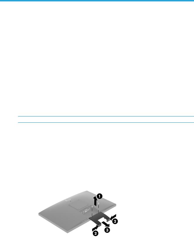
Removing the rear port cover
1.Prepare the computer for disassembly (see Preparing to disassemble the computer on page 18).
2.If the security lock screws are secured, use a T15 tamper-resistant Torx security screwdriver to remove both screws (1).
3.Slide the rear port cover retainer tabs toward each other (2) to release the port cover.
4. Pull the port cover (3) toward the bottom and o the computer.
18 Chapter 4 Removal and Replacement Procedures
Stands
Two stands are available for the computer:
●Recline stand
●Adjustable height stand
Recline stand
To remove the stand:
1.Prepare the computer for disassembly (see Preparing to disassemble the computer on page 18).
2.Remove the rear port cover, if it is installed. For instructions, see Removing the rear port cover on page 18.
3.Press the release latch under the stand (1).
4.Lift the stand up (2), and then pull the stand hooks out of the computer (3).
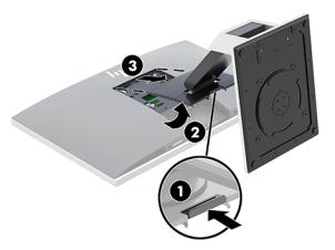
Adjustable height stand
To remove the stand:
1.Prepare the computer for disassembly (see Preparing to disassemble the computer on page 18).
2.Remove the rear port cover, if it is installed. For instructions, see Removing the rear port cover on page 18.
3.Press the release latch under the stand (1).
Stands 19
4.Lift the stand up (2), and then pull the stand hooks out of the computer (3).
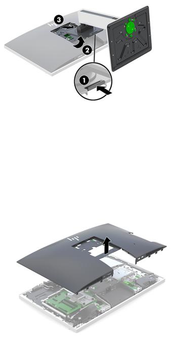
Access panel
The computer has one main rear access panel that allows access to internal components. To remove the access panel:
1.Prepare the computer for disassembly (see Preparing to disassemble the computer on page 18).
2.Remove the rear port cover (see Removing the rear port cover on page 18).
3.Remove the stand (see Stands on page 19).
4. Pull up the notches of the access panel, and then lift the access panel o the computer.
To replace the access panel, reverse the removal procedures.
20 Chapter 4 Removal and Replacement Procedures

Locating internal components
Component |
|
Component |
|
|
|
|
|
1 |
Memory modules |
3 |
Hard drive |
|
|
|
|
2 |
RTC battery |
4 |
Optical disc drive (optional) |
|
|
|
|
Locating internal components 21
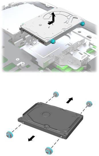
Hard drive
The 2.5 inch primary hard drive is installed on the right side of the computer on top of the optical disc drive (ODD). To locate the hard drive on the system board, see Locating internal components on page 21.
For a list of available hard drives, see Mass storage devices on page 9.
1.Prepare the computer for disassembly (see Preparing to disassemble the computer on page 18).
2.Remove the rear port cover (see Removing the rear port cover on page 18).
3.Remove the stand (see Stands on page 19).
4.Remove the access panel (see Access panel on page 20).
5.Pull the hard drive latch away from the hard drive to release the drive (1).
6.Slide the hard drive toward the edge of the computer and lift the hard drive out of the drive cage (2).
7.Remove the four mounting screws from the 2.5 inch hard drive. Be sure to keep the screws together with the blue rubber grommets to use to install a replacement drive.
To install a hard drive, reverse the disassembly instructions.
22 Chapter 4 Removal and Replacement Procedures
Loading...