


Agilent 34401A Multimeter
Uncompromising Performance for Benchtop and System Testing
Product Overview
•Measure up to 1000 volts with 61 ⁄2 digits resolution
•0.0015% basic dcV accuracy
(24 hour)
•0.06% basic acV accuracy (1 year)
•3Hz to 300kHz ac bandwidth
•1000 readings/sec. direct to GPIB
Superior performance
The Agilent Technologies 34401A multimeter gives you the performance you need for fast, accurate bench and system testing. The 34401A provides a combination of resolution, accuracy and speed that rivals DMMs costing many times more. 61⁄2-digits of resolution, 0.0015% basic 24-hr dcV accuracy and 1,000 readings/sec direct to GPIB assure you of results that are accurate, fast, and repeatable.
Use it on your benchtop
The 34401A was designed with your bench needs in mind. Functions commonly associated with bench operation, like continuity and diode test, are built in. A Null feature allows you to remove lead resistance and other fixed offsets in your measurements.
Other capabilities like min/max/avg readouts and direct dB and dBm measurements make checkout with the 34401A faster and easier.
The 34401A gives you the ability to store up to 512 readings in internal memory. For trouble-shooting, a reading hold feature lets you concentrate on placing your test leads without having to constantly glance at the display.
Use it for systems testing
For systems use, the 34401A gives you faster bus throughput than any other DMM in its class. The 34401A can send up to 1,000 readings/sec directly across GPIB in user-friendly ASCII format.
You also get both GPIB and RS-232 interfaces as standard features. Voltmeter Complete and External Trigger signals are provided so you can synchronize to other instruments in your test system. In addition, a TTL output indicates Pass/Fail results when limit testing is used.
To ensure both forward and backward compatibility, the 34401A includes three command languages (SCPI, Agilent 3478A and Fluke 8840A /42A), so you don’t have to rewrite your existing test software. An optional rack mount kit is available.
Easy to use
Commonly accessed attributes, such as functions, ranges, and resolution are selected with a single button press.
Advanced features are available using menu functions that let you optimize the 34401A for your applications.
The included Agilent IntuiLink software allows you to put your captured data to work easily, using PC applications such as Microsoft Excel® or Word® to analyze, interpret, display, print, and document the data you get from the 34401A. You can specify the meter setup and take a single reading or log data to the Excel spreadsheet in specified time intervals. Programmers can use ActiveX components to control the DMM using SCPI commands. To find out more about IntuiLink, visit www.agilent.com/find/intuilink
1-year Warranty
With your 34401A, you get full documentation, a high-quality test lead set, calibration certificate with test data, and a 1-year warranty, all for one low price.
Accuracy Specifications ± (% of reading + % of range) [1]
|
|
|
|
|
|
|
Temperature |
|
|
|
|
|
|
|
|
Coefficient |
|
|
|
Frequency, |
24 Hour [2] |
90 Day |
1 Year |
0°C – 18°C |
||
Function |
Range[3] |
etc. |
23°C ± 1°C |
23°C ± 5°C |
23°C ± 5°C |
28°C – 55°C |
||
|
|
|
|
|
|
|
|
|
dc Voltage |
100.0000 mV |
|
|
0.0030 + 0.0030 |
0.0040 + 0.0035 |
0.0050 + 0.0035 |
0.0005 + 0.0005 |
|
|
1.000000 V |
|
|
0.0020 + 0.0006 |
0.0030 + 0.0007 |
0.0040 + 0.0007 |
0.0005 + 0.0001 |
|
|
10.00000 V |
|
|
0.0015 + 0.0004 |
0.0020 + 0.0005 |
0.0035 + 0.0005 |
0.0005 + 0.0001 |
|
|
100.0000 V |
|
|
0.0020 + 0.0006 |
0.0035 + 0.0006 |
0.0045 + 0.0006 |
0.0005 + 0.0001 |
|
|
1000.000 V |
|
|
0.0020 + 0.0006 |
0.0035 + 0.0010 |
0.0045 + 0.0010 |
0.0005 + 0.0001 |
|
|
|
|
|
|
|
|
|
|
True rms |
100.0000 mV |
3 |
Hz - 5 Hz |
1.00 + 0.03 |
1.00 + 0.04 |
1.00 + 0.04 |
0.100 |
+ 0.004 |
ac Voltage[4] |
|
5 |
Hz - 10 Hz |
0.35 + 0.03 |
0.35 + 0.04 |
0.35 + 0.04 |
0.035 |
+ 0.004 |
|
|
10 Hz - 20 kHz |
0.04 + 0.03 |
0.05 + 0.04 |
0.06 + 0.04 |
0.005 |
+ 0.004 |
|
|
|
20 kHz - 50 kHz |
0.10 + 0.05 |
0.11 + 0.05 |
0.12 + 0.04 |
0.011 |
+ 0.005 |
|
|
|
50 kHz - 100 kHz |
0.55 + 0.08 |
0.60 + 0.08 |
0.60 + 0.08 |
0.060 |
+ 0.008 |
|
|
|
100 kHz - 300 kHz[6] |
4.00 + 0.50 |
4.00 + 0.50 |
4.00 + 0.50 |
0.20 + 0.02 |
||
|
|
|
|
|
|
|
|
|
|
1.000000 V |
3 |
Hz - 5 Hz |
1.00 + 0.02 |
1.00 + 0.03 |
1.00 + 0.03 |
0.100 |
+ 0.003 |
|
to |
5 |
Hz - 10 Hz |
0.35 + 0.02 |
0.35 + 0.03 |
0.35 + 0.03 |
0.035 |
+ 0.003 |
|
750.000 V |
10 Hz - 20 kHz |
0.04 + 0.02 |
0.05 + 0.03 |
0.06 + 0.03 |
0.005 |
+ 0.003 |
|
|
|
20 kHz - 50 kHz |
0.10 + 0.04 |
0.11 + 0.05 |
0.12 + 0.04 |
0.011 |
+ 0.005 |
|
|
|
50 kHz - 100 kHz[5] |
0.55 + 0.08 |
0.60 + 0.08 |
0.60 + 0.08 |
0.060 |
+ 0.008 |
|
|
|
100 kHz - 300 kHz[6] |
4.00 + 0.50 |
4.00 + 0.50 |
4.00 + 0.50 |
0.20 + 0.02 |
||
|
|
|
|
|
|
|
||
Resistance[7] |
100.0000 Ω |
1 mA Current Source |
0.0030 + 0.0030 |
0.008 + 0.004 |
0.010 + 0.004 |
0.0006 + 0.0005 |
||
|
1.000000 kΩ |
1 mA |
0.0020 + 0.0005 |
0.008 + 0.001 |
0.010 + 0.001 |
0.0006 + 0.0001 |
||
|
10.00000 kΩ |
100 µA |
0.0020 + 0.0005 |
0.008 + 0.001 |
0.010 + 0.001 |
0.0006 + 0.0001 |
||
|
100.0000 kΩ |
10 µA |
0.0020 + 0.0005 |
0.008 + 0.001 |
0.010 + 0.001 |
0.0006 + 0.0001 |
||
|
1.000000 MΩ |
5.0 µA |
0.002 + 0.001 |
0.008 + 0.001 |
0.010 + 0.001 |
0.0010 + 0.0002 |
||
|
10.00000 MΩ |
500 nA |
0.015 + 0.001 |
0.020 + 0.001 |
0.040 + 0.001 |
0.0030 + 0.0004 |
||
|
100.0000 MΩ |
500 nA || 10MΩ |
0.300 + 0.010 |
0.800 + 0.010 |
0.800 + 0.010 |
0.1500 + 0.0002 |
||
|
|
|
|
|
|
|
|
|
dc Current |
10.00000 mA |
<0.1 V Burden Voltage |
0.005 + 0.010 |
0.030 + 0.020 |
0.050 + 0.020 |
0.002 |
+ 0.0020 |
|
|
100.0000 mA |
<0.6 V |
0.010 + 0.004 |
0.030 + 0.005 |
0.050 + 0.005 |
0.002 |
+ 0.0005 |
|
|
1.000000 A |
<1 V |
0.050 + 0.006 |
0.080 + 0.010 |
0.100 + 0.010 |
0.005 |
+ 0.0010 |
|
|
3.00000 A |
<2 V |
0.100 + 0.020 |
0.120 + 0.020 |
0.120 + 0.020 |
0.005 |
+ 0.0020 |
|
|
|
|
|
|
|
|
|
|
True rms |
1.000000 A |
3 |
Hz - 5 Hz |
1.00 + 0.04 |
1.00 + 0.04 |
1.00 + 0.04 |
0.100 |
+ 0.006 |
ac Current[4] |
|
5 |
Hz - 10 Hz |
0.30 + 0.04 |
0.30 + 0.04 |
0.30 + 0.04 |
0.035 |
+ 0.006 |
|
|
10 Hz - 5 kHz |
0.10 + 0.04 |
0.10 + 0.04 |
0.10 + 0.04 |
0.015 |
+ 0.006 |
|
|
|
|
|
|
|
|
|
|
|
3.00000 A |
3 |
Hz - 5 Hz |
1.10 + 0.06 |
1.10 + 0.06 |
1.10 + 0.06 |
0.100 |
+ 0.006 |
|
|
5 |
Hz - 10 Hz |
0.35 + 0.06 |
0.35 + 0.06 |
0.35 + 0.06 |
0.035 |
+ 0.006 |
|
|
10 Hz - 5 kHz |
0.15 + 0.06 |
0.15 + 0.06 |
0.15 + 0.06 |
0.015 |
+ 0.006 |
|
|
|
|
|
|
|
|
|
|
Frequency |
100 mV |
3 |
Hz - 5 Hz |
0.10 |
0.10 |
0.10 |
0.005 |
|
or Period[8] |
to |
5 |
Hz - 10 Hz |
0.05 |
0.05 |
0.05 |
0.005 |
|
|
750 V |
10 Hz - 40 Hz |
0.03 |
0.03 |
0.03 |
0.001 |
|
|
|
|
40 Hz - 300 kHz |
0.006 |
0.01 |
0.01 |
0.001 |
|
|
|
|
|
|
|
|
|
|
|
Continuity |
1000.0Ω |
1mA Test Current |
0.002 + 0.010 |
0.008 + 0.020 |
0.010 + 0.020 |
0.001 |
+ 0.002 |
|
|
|
|
|
|
|
|
|
|
Diode Test [9] |
1.0000V |
1mA Test Current |
0.002 + 0.010 |
0.008 + 0.020 |
0.010 + 0.020 |
0.001 |
+ 0.002 |
|
|
|
|
|
|
|
|
|
|
|
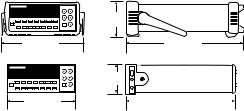
103.6 mm |
254.4 mm |
374.0 mm |
|
88.5 mm |
212.6 mm |
348.3 mm |
[1]Specifications are for 1hr warm-up and 61⁄2 digits, Slow ac filter.
[2]Relative to calibration standards.
[3]20% over range on all ranges except 1000 Vdc and 750 Vac ranges.
[4]For sinewave input > 5% of range. For inputs from 1% to 5% of range and < 50 kHz, add 0.1% of range additional error.
[5]750 V range limited to 100 kHz or 8 x10⁷ Volt-Hz.
[6]Typically 30% of reading error at 1 MHz.
[7]Specifications are for 4-wire ohms function or 2-wire ohms using Math Null. Without Math Null, add 0.2 Ω additional error in 2-wire ohms function.
[8]Input >100 mV. For 10 mV to 100 mV inputs multiply % of reading error x10.
[9]Accuracy specifications are for the voltage measured at the input terminals only. 1mA test current is typical. Variation in the current source will create some variation in the voltage drop across a diode junction.
2
 Loading...