


L4081A,B AND L6081A,C MULTIPLE AQUASTAT® CONTROLLERS
INSTALLATION
When Installing This Product…
1.Read these instructions carefully. Failure to follow them could damage the product or cause a hazardous condition.
2.Check the ratings given in the instructions and on the product to make sure the product is suitable for your application.
3.Installer must be a trained, experienced service technician.
4.After installation is complete, check out product operation as provided in these instructions.
 WARNING
Electrical Shock Hazard.
Can cause serious injury, death or equipment damage.
Disconnect power supply before installation to prevent electrical shock or equipment damage.
NOTE: These devices can be installed in any position. Proper location, sizing and threaded boiler tapping are required.
1.Maximum pressure rating for these models is 200 psi (1380 kPa)
2.Maximum permissible ambient temperature as sensing bulb is 265°F (130°C); at switches, 150°F (66°C).
3.The L6081C is without enclosure or well assembly.
Mounting
Followinstructions provided by system manufacturer, if available. Otherwise, proceed as follows:
1.Drain the boiler if the system is filled with water.
2.Place the front of the controller down on a horizontal surface and gently raise the sensing bulb until it is at a right angle with the back of the case and centered with the alrge hole in the case. This requires bending the capillary tube, but be sure to make no sharp bends and no bends near the bulb.
NOTE: Some models have an adjustable tubing length to 3 in. (76 mm). In these models, extra tubing inside the case can be pulled out, if needed. See Fig. 3.
3
1
2
 CAUTION:
EXCESSIVE HANDLING OR SHARP BENDS
CAN DAMAGE THE CAPILLARY.
1SENSING ELEMENT IS FACTORY FORMED FOR 1.5 IN. INSULATION WELL ASSEMBLIES.
2FOR 3 IN. INSULATION WELL ASSEMBLIES, PULL OUT SUFFICIENT CAPILLARY TO ASSURE THAT THE CAPSULE BOTTOMS IN THE WELL.
3STRAIGHTEN CAPILLARY SUFFICIENTLY SO IT DOES NOT
INTERFERE WITH INSERTION OF THE CAPSULE INTO THE WELL. M8882
Fig. 3. Adjusting the capillary length.
3.Adjust the position of the bulb so tht the bulb projects 4-7/8 in. (124 mm) from the back of the case for immersion well designed for 1-1/2 in. (38 mm) insulation; or 6-3/8 in. (162 mm), if designed for 3 in. (76 mm) insulation. If this requires bending the tube inside the case, insert the end of your index finger through the hole and carefully mold the tube into the correct shape as you gently pull (or push) the bulb to the correct position. The bulb must project the right distance so that after the case in installed, the spring force of the capillary tube holds the bulb against the inner end of the well for good thermal contact. The tube must be straight for at least 3/8 in. (10 mm) inside the case so the end of the well spud does not strike the coiled tube and pull the bulb away from contact with the inner end of the well.
4.Remove the plug from a properly located boiler tapping.
5.Apply pipe dope sparingly to the threads of the well, then screw the well tightly into the boiler tapping.
6.Fill the system with water, then carefully examine around the threads for leakage. Tighten the well if necessary to stop any leakage.
7.Loosen the wallclamp screw three or four turns., move the screw in and out and not how it moves the well clamp. See Fig. 4. Loosen the screw enough so that when the screw is pushed inward, the T-shaped clamp guide is at the far end of the slot in the case.
8.Mount the case on the well spud in any position that facilitates wiring. With the case in final position, carefully insert the sensing bulb into the well until the case slips over the end of the well spud and fits squarely against the shoulder of the spud.
NOTE: Open the clamp to receive the spud by pushing in the well clamp screw.
9.While holding the case in the correct position, firmly tighten the well clamp screw.
60-2105—6 |
4 |

L4081A,B AND L6081A,C MULTIPLE AQUASTAT® CONTROLLERS
STRIP |
WELL CLAMP |
GAUGE |
SCREW |
LOW LIMIT/
CIRCULATOR
DIFFERENTIAL
ADJUSTMENT
LOW LIMIT
SETPOINT
ADJUSTMENT
HIGH LIMIT |
|
|
SETPOINT |
|
M8848 |
ADJUSTMENT |
JUMPER |
SLOT
Fig. 4. L6081A with cover removed to show adjustments.
WIRING
 WARNING
Electrical Shock Hazard.
Can cause serious injury, death or equipment damage.
Disconnect the power supply to prevent electrical shock or equipment damage.
IMPORTANT
Use care to avoid strain on the control case when using cable or conduit.
 WARNING
Explosion Hazard.
Can cause serious injury, death or property damage.
Use this product only in a system with a pressure relief valve.
Alll wiring must comply with all applicable local codes and ordinances. See cover insert for electrical load ratings. Refer to Fig. 5 through 9 for typical wiring diagrams.
Use the following procedure when connecting wires to the B-B tab terminals (Fig. 4):
1.Connect no. 14, 16, or 18 solid, or no. 14 or 16 unistranded wire to the tab terminals.
2.Strip insulation from the end of each wire.
3.use the included wire nut from the bag assemblyh to connect the tab terminal connector to the wire.
4.Connect the wire to the tab terminal.
Use the following procedures when connecting wires to the R-R terminals (Fig. 4):
1.Use no. 14, 16, or 18 solid, or no. 14 or 16 unistranded wire for connecting the push-in terminals.
2.Strip the insulation from the end of each wire.
3.Insert a screwdriver into the rectangular slot near the terminal and hold it in the slot while inserting the wire into the terminal hole as far as possible.
4.Remove the screwdriver when complete.
Jumper
When using the controller field addable jumper (Fig. 4), connect terminals R-R. When the jumper is added, make sure that the two prongs of the jumper face the center of the controller.
L2 |
|
L1 |
|
|
|
|
|
(HOT) |
|
|
|
||
|
1 |
|
|
|
|
|
|
|
|
|
|
|
|
|
|
|
L4081A |
|
2 |
LIMITLOW |
|
CIRCULATOR |
LIMITHIGH |
B |
B |
||
|
|
|
|
|
|
VR8300 |
|
|
|
|
R |
R |
LOW |
|
|
|
|
|
|
VOLTAGE |
|
|
|
|
|
|
GAS |
|
|
|
|
|
|
VALVE |
2 |
4 |
3 |
1 |
|
|
|
24V |
|
|
|
|
|
|
THERMOSTAT |
|
|
|
|
|
|
|
RA832A |
|
X |
|
|
|
|
SWITCHING |
|
|
|
||
|
|
|
|
|
||
|
RELAY |
|
1R2 |
|
|
|
T |
|
|
X |
|
|
|
|
|
|
|
|
|
|
|
1R |
|
|
|
|
|
T |
|
|
|
|
|
JUMPER |
|
|
|
|
|
|
|
|
|
|
|
|
|
REMOVED |
1POWER SUPPLY. PROVIDE DISCONNECT MEANS AND OVERLOAD PROTECTION AS REQUIRED.
M8846
2 B TERMINALS ARE TAB TERMINALS.
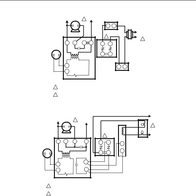
Fig. 5. L4081A used with gas burner (line voltage limit).
L2 |
|
|
|
|
|
1 |
|
|
|
|
|
L1 |
|
|
|
|
|
(HOT) |
|
|
|
|
|
2 |
HIGH LIMIT |
B |
W |
CIRCULATOR |
CIRCULATOR |
|
|
|
RELAY |
||
L4081B |
|
|
|
||
|
R |
R |
|
||
|
|
|
|
||
BURNER |
|
|
|
|
CIRCULATOR |
CONTROL |
|
|
|
|
MOTOR |
|
|
|
|
|
JUMPER |
|
|
|
|
|
REMOVED |
1POWER SUPPLY. PROVIDE DISCONNECT MEANS AND OVERLOAD PROTECTION AS REQUIRED.
2 B IS A TAB TERMINAL. |
M8787 |
Fig. 6. L4081B used to prevent circulator opertion with boiler water temperature below low limit setting.
5 |
60-2105—6 |
L4081A,B AND L6081A,C MULTIPLE AQUASTAT® CONTROLLERS
|
|
|
|
L1 |
|
|
PILOTSTAT® |
|
|
L2 |
|
1 |
(HOT) |
|
|
||
|
|
|
|
CONTROL |
||||
|
|
|
|
|
|
|
||
|
CIRCULATOR |
|
|
|
|
|
|
|
|
|
|
|
|
LIMITHIGH |
|
2 |
LIMITLOW |
24V |
2 |
4 |
3 |
1 |
B |
B |
||
THERMO- |
|
1R1 |
|
|
|
|
||
|
|
|
|
|
|
|
||
STAT |
|
|
|
|
|
|
|
|
|
|
|
|
|
|
R |
R |
|
|
|
|
|
|
L4081A |
|
||
|
T |
|
|
|
|
|
|
|
|
T |
1R |
|
|
|
|
|
GAS VALVE |
|
|
|
|
|
|
|
|
|
RA89A SWITCHING RELAY
1POWER SUPPLY. PROVIDE DISCONNECT MEANS AND OVERLOAD PROTECTION AS REQUIRED.
2 B TERMINALS ARE TAB TERMINALS. |
M8788 |
L1
(HOT)
L2
1
Fig. 7. L4081A used with burner cycled from the water temperature.
L2 |
1 |
L1 |
|
(HOT) |
|||
|
|
|
CIRCULATOR |
|
|
LIMITHIGH |
|
2 |
LIMITLOW |
2 |
4 |
3 |
1 |
B |
B |
||
24V |
|
|
1R1 |
|
|
||
|
|
|
|
|
|
||
THERMOSTAT |
|
|
|
|
|
|
|
|
|
|
|
|
R |
R |
|
|
|
|
|
L4081A |
|
|
|
T |
|
|
X |
|
|
|
|
|
|
1R2 |
|
|
|
|
|
|
|
|
|
|
|
|
|
T |
1R |
|
X |
|
|
|
|
RA832A SWITCHING RELAY |
|
|
|
|
|||
L1
(HOT)
BLACK |
1 |
WHITE
L2
JUNCTION
BOX
T
T
OIL PRIMARY
CONTROL
1POWER SUPPLY. PROVIDE DISCONNECT MEANS AND OVERLOAD PROTECTION AS REQUIRED.
2 B TERMINALS ARE TAB TERMINALS. |
M8786 |
Fig. 8. L4081A used with oil burner.
60-2105—6 |
6 |
 Loading...