


INNCOM e7
Table of contents
 Loading...
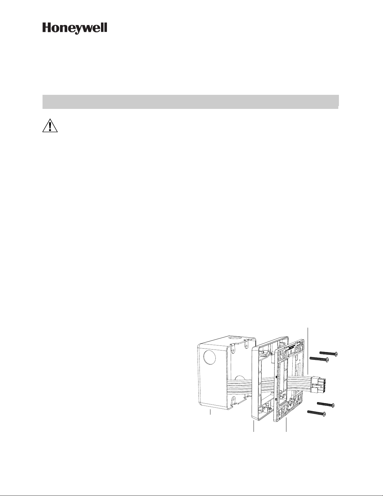
INSTALLATION INSTRUCTIONS
INNCOM e7 Thermostat
Installation Instructions
FOR ALL UNITS IN CARTON. DO NOT THROW AWAY!
CAUTION
Disconnect the power supply before beginning
installation to prevent electrical shock or
equipment damage. All wiring must comply with
local codes and ordinances.
• Read instructions carefully. Failure to follow them could
damage the product or create a hazard.
• Check the ratings given in the instructions and on the
product to make sure the product is suitable for your
application.
• Installer must be a trained, experienced service technician.
• After installation is complete, check product operation as
indicated in instructions.
• For variations of these systems, refer to the installation
instructions of the controlled equipment.
INSTALLATION
Location
Select a location about 1.5m (5ft.) above the floor with good
air circulation at average temperature. Do not mount
thermostat where it may be affected by:
• Drafts or dead spots behind doors or in corners.
• Hot or cold air from ducts.
• Radiant heat from sun or appliances.
• Concealed pipes or chimneys.
• Unheated (un-cooled) areas behind the thermostat.
• If RF equipped, do not install near other RF sources/
transmitters.
• When the thermostat is equipped with PIR, consider view
angle, range characteristics, and mounting position for
proper coverage.
Mounting
The INNCOM e7 thermostat is typically mount on a standard
double-gang (4 x 4) junction box. The installation kit
provides a Smart Wall Mounting Plate and an optional
Spacer Ring. The optional Spacer Ring is only required
when a standard double-gang (4 x 4) junction box is not
available, or when more space is required for wiring.
If mounted on a single-gang box, the right side (keypad side) of
the e7 overlaps the wall area to the right. A low-voltage
mounting plate, mud ring, or low-voltage caddy may be used
for mounting 24 volt applications.
To mount the e7, complete the following steps:
1. Position the optional spacer ring (if used) and Smart
Wall Mounting Plate as shown in Fig. 1.
2. Ensure the optional spacer ring (if used) and Smart
Mounting Plate are oriented with the raised arrow point-
ing UP. Snap them together, ensuring all 4 corner snap
hooks are attached, then attach them to the junction box
using the supplied screws.
3. Use wire nuts to connect the Power and HVAC wiring
harness to the power and valve/fan control signal wires
within the electrical box. See the pre-defined commis-
sioning document for application-specific wire connec-
tions.
4. To connect the unit to the input power and the relays to
the loads, plug the pre-wired power and HVAC signal
harness connector into the female receptacle at the back
of the e7 (H1). When using mixed voltage, voltage sepa-
ration must be maintained. Line voltage must reside in
the left side of the gang box. Low voltage must reside in
the right side of the gang box.
5. Hook the tabs at the top rear of the e7 housing into the
matching depressions at the top of the Smart Mounting
Plate and rotate the bottom of the housing toward the
wall until it snaps into place.
6. Secure the housing to the Smart Mounting Plate with the
two small captive screws at the bottom of the housing.
7. Apply power to the e7 by closing the applicable supply
breaker. After connecting power, wait 5 seconds. values
will begin appearing on the LCD display.
Fig. 1. e7 Exploded View Assembly Reference
Optional Spacer Ring
4x4 Junction Box
Smart Mounting Ring
Power/HVAC signal
harness to thermostat
INNCOM E7 THERMOSTAT INSTALLATION INSTRUCTIONS
36-00012—01 2
WIRING
Wiring Diagrams
Before getting started on an installation, use the templates
at the back of this guide to identify the wires/signals coming
out of the 4 x 4 box and figure out what wires are connected
to which wires on the thermostat. This provides a quick and
easy cheat sheet to capture property specific wiring
requirements.
NOTE:
If the HVAC configuration for your application is not
shown here, refer to the document: e7 Wiring Configurations
found online at:
https://pages1.honeywell.com/e7_Install_Instructions.html
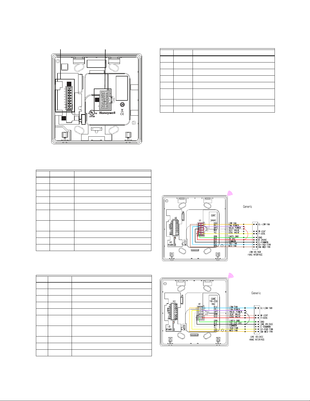
Generic FCU:24 VAC
Generic FCU: 100-277 VAC
Table 1. H1 Red Connector: 24 VAC Power/HVAC Sig-
nals
Pin Color Typical Function
1 Green Ground
2 Red 24 VAC
3 Black Common
4Blue High Fan
5 Brown Medium Fan or Second Stage Heat
6 Yellow Cold Water Valve (FCU) or Compressor
Signal (Heat Pump)
7 White Hot Water Valve (FCU) or Reversing Valve
(Heat Pump)
8Grey Valve Power
9 Violet Fan Power
10 Orange Low Fan
Table 2. H1 White Connector: 100-277 VAC Power/
HVAC Signals
Pin Color Typical Function
1 Green Ground
2 Black Line
3 White Neutral
4 Yellow High Fan
5 Orange Medium Fan or Second Stage Heat
6 Red Cold Water Valve (FCU) or Compressor
Signal (Heat Pump)
7 Brown Hot Water Valve (FCU) or Reversing Valve
(Heat Pump)
8Grey Valve Power
9Violet Fan Power
10 Blue Low Fan
H1
FCC ID: HS9-20152824
Niantic, CT 06357
Country of Origin: Mexico
Patent Pending
AI
1
10
AO
DIN3
DIN2
DIN1
S5bus
12VDC
GND
IC: 573R-20152824
BLE
H4
RS485
Model No: 201-528-100/277-WH
OS No:
201-528-100/277-WH
Input:
220 VAC
Heat/Cool:
XXXX
Low/Med Fan:
XXXX
High Fan:
XXXX
Date Code:
XXXX-XX-XX SW Ver.:
3.1.1
H1
H3
H2
Honeywell GmbH
Boeblinger Str. 17
71101 Schoenaich
Germany
E361577
Sensing Control
H2 - Low Voltage Signals
H1 - Power/HVAC Signals
Table 3. H2 Low Voltage Signals
Pin Signal Typical Function
1 GND Ground
2 VEE 12 VDC
3 S5bus Communications
4 DIN1 Entry Door, 2 transitions to active
5 DIN2 Balcony Door/Window, 2 transitions to active
6 DIN3 External PIR/Motion Sensor, 2 transitions to
active
7 AO 0-10 V VFD Fan
8 AI Remote Thermistor
INNCOM E7 THERMOSTAT INSTALLATION INSTRUCTIONS
3 36-00012—01
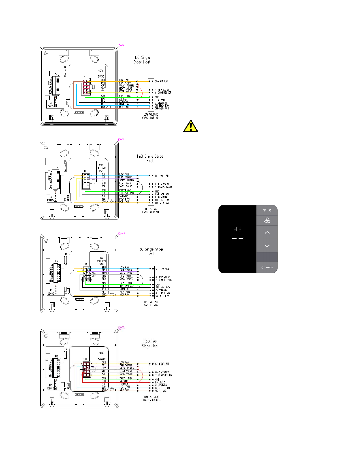
HpB Single-Stage Heat: 24 VAC
HpB Single-Stage Heat: 100-277 VAC
HpO Single-Stage Heat: 100-277 VAC
HpO Two-Stage Heat: 24 VAC
INITIAL SETUP
Before going through the initial setup sequences, ensure
the thermostat is mounted and connected to the Smart Wall
Plate.
NOTE: Prior to completing Initialization Mode, or pushing the
thermostat configuration from engINN, the thermostat is
configured with factory defaults to disable any call for heat,
cool, or low, medium and high fan speeds to protect the HVAC
equipment.
When properly connected, the thermostat will proceed into
INTIALIZATION MODE and display
rId.
When not properly connected to the Smart Wall
Plate, the unit will display the alert message
SWp and
the alert icon will illuminate until the Smart Wall
Plate is connected.
If you see
SWp on the display, most likely the unit is
not connected or properly seated on the Smart Wall
Plate. Unscrew the captive screws and re-seat the
thermostat. Once properly connected, the display will
start up as noted. Take care not to over-tighten the
screws and note any irregularity on the wall surface
that may lead to an insecure connection between the
Smart Wall Plate and thermostat.
SETUP ROOM ID
1. Once
rid is displayed, press MODE. The default Room
ID value (65535) is displayed and will begin scrolling
across the screen one numerical setting at a time, from
highest to lowest (left most to right most value). Note
that the five-digit number is comprised of three fields:
highest digit, middle two digits, lowest two digits. Three
settings must be made.
2. Scrolling will stop at the highest digit first. Use the UP/
DOWN arrow buttons to change this value (range is 0-
6). Press FAN to continue.
3. Set the next two values in the sequence using the UP/
DOWN arrow buttons (range is 0-99). Press FAN to
continue. Repeat this step for the lowest two values
(range is 0-99) and press FAN. Press MODE to accept
the value.
4. The new ID number scrolls across the display. The unit
beeps when the value is stored to memory. Once the
scrolling is completed, Press the DOWN arrow button to
display HVAC (HAC) menu.
Loading...