


MILVIZ DHC2 Beaver
Honeywell KAP 140 Autopilot system
(Sources: Honeywell KAP 140 Pilot’s guide – Honeywell KAP 140 Installation Manual)
KAP 140 Two Axis with Altitude Preselect Operation - Introduction
The KAP 140 Autopilot System included in the Beaver is a rate based digital autopilot system offering smooth performance and enhanced features found only in more expensive autopilots. The first of its type developed by Honeywell, this system brings digital technology and reliability into the light aircraft cockpit.
KAP 140 roll axis features include wing leveler, heading select and VOR/LOC intercept and tracking. The KAP 140 can also be coupled to GPS and RNAV receivers as well. Roll rate information is derived from the turn coordinator.
Pitch axis features include vertical speed, glideslope and altitude hold along with altitude preselect option. Pitch information is derived from a pressure sensor and accelerometer.
The KAP 140 Autopilot System operates independe. Therefore, the autopilot retains roll stabilization and all vertical modes in the event of vacuum system failure.
KAP 140 features in Beaver’s version
DG (Directional Gyro) |
YES |
Turn Coordinator |
YES |
Automatic Electric Elevator Trim |
NO |
Manual Electric Trim |
NO |
FUNCTION MODES |
ALT Hold (ALT); ALT Preselect/ALERT; Heading Select (HDG); |
|
NAV (VOR/RNAV/GPS); Approach (APR); Glideslope (GS); |
|
Back Course (REV); Wing Leveler (ROL); Vertical Speed Hold (VS) |
|
|
Control Wheel Steering (CWS) |
NO |
Auto Capture |
YES |
Auto Track |
YES |
All Angle Intercept |
YES (from ROL mode) |
Auto 45-degree Intercept |
YES (from HDG mode) |
Remote Barometric Input |
NO |
1

Diagram - KAP 140 Beaver’s version systems
WARNING!:
No Automatic Elevator Trim available. Aircraft must be properly trimmed before engaging/disengaging the autopilot.
Each system has a number of inputs: sensor outputs are shown in red; combination inputs are shown in blue; display outputs are shown in orange; and aircraft control shown in green.
2
System Technical Characteristics (In smooth air)
Maximum Bank Angles |
Limited to standard rate turn. |
|
|
|
|
Heading Stability |
± 2° |
|
|
|
|
VOR Crosswind Compensation |
Up to 30° right or left |
|
|
|
|
NAV/APR/REV Capture Capability |
All angles |
|
|
|
|
NAV/APR/REV Capture Computation |
Scheduled by beam closure rate |
|
|
|
|
NAV Track Computation |
Scheduled by beam rate and deviation |
|
|
|
|
APR/REV Track Computation |
Scheduled by beam rate and deviation |
|
|
|
|
|
System will track without large bank angles |
|
NAV Tracking |
keeping beam deviation to less than 1.0° of |
|
VOR. Actual performance will depend |
||
|
||
|
upon quality of VOR beam being received |
|
|
|
|
|
System will track without large bank angles |
|
LOC Tracking |
keeping beam deviation to less than .25° of |
|
LOC. Actual performance will depend upon |
||
|
||
|
quality of LOC beam being received. |
|
|
|
|
Vertical Speed Stability |
± 150 feet per minute |
|
|
|
|
Altitude Range |
-- 1000 to 35,000 ft |
|
|
|
|
Altitude Hold Stability |
± 50ft |
|
|
|
|
|
System will limit overshoot to less than 100 |
|
Altitude Overshoot |
feet of selected altitude across the altitude |
|
range of the aircraft. When armed prior to |
||
|
||
|
the capture point. |
|
|
Mode Continuous Discrete |
|
Vertical Trim |
ALH 500 FPM 20 Feet |
|
|
VS 300 FPM/SEC 100 FPM |
|
Glideslope Capture Computation |
Scheduled by beam rate and deviation |
|
|
|
|
Autopilot Disconnect Alerting |
External Sonalert |
|
|
|
|
Software version |
03/01 and later |
|
|
|
3
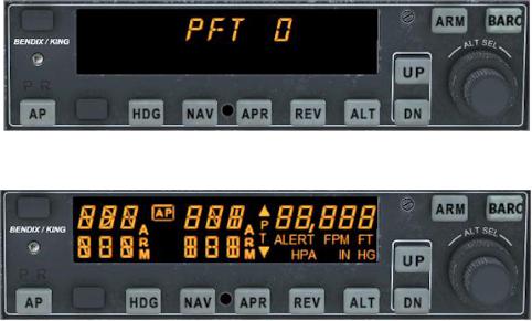
Power Application and Preflight Tests
KAP 140 Preflight Test
KAP 140 Preflight Test Complete
A preflight test is performed upon power application to the computer. This test is a sequence of internal checks that validate proper system operation prior to allowing
autopilot engagement. The preflight test (PFT) increasing number for the sequence steps. Successful completion of self test is identified
by all display segments being illuminated (Display Test) and the disconnect tone sounding.
Following the preflight test, the red P warning on the face of the autopilot may illuminate indicating that the pitch axis cannot be engaged. This condition should be temporary, lasting no more than 30 seconds. The P will extinguish and normal operation will be available.
Red P and R warnings may illuminate when the autopilot is not engaged. This can occur when autopilot G limits have been exceeded during turbulence or aircraft maneuvering. Autopilot engagement is locked out during red R illumination.
4
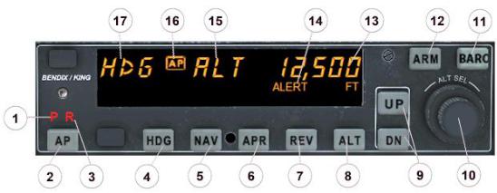
KAP 140 Two Axis with Altitude Preselect Operation
1. PITCH AXIS, (P) ANNUNCIATOR
- When illuminated, indicates failure of the pitch axis and will disengage the autopilot when the failure occurs and not allow engagement of the pitch axis.
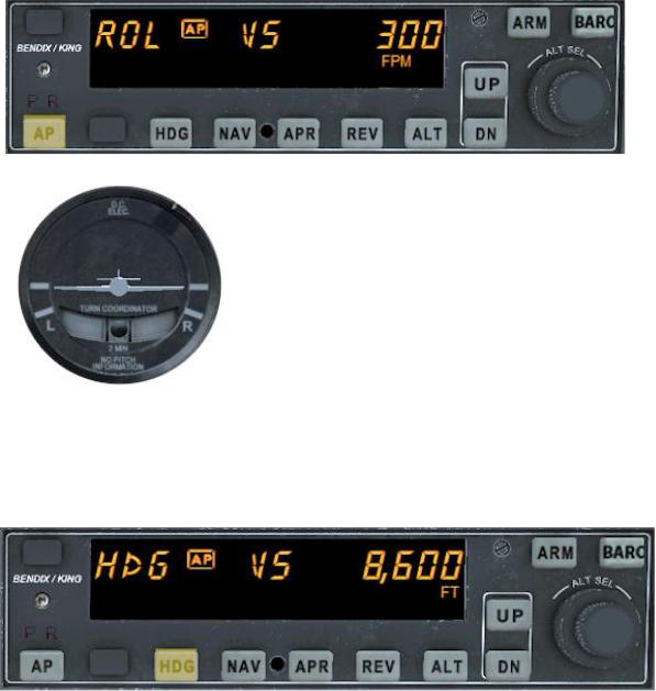
2. AUTOPILOT ENGAGE/DISENGAGE (AP) BUTTON
- When pushed and held for 0.25 seconds, engages autopilot if all logic conditions are met. The autopilot will engage in the basic roll (ROL) mode which functions as a wing leveler and in the vertical speed (VS) hold mode. The commanded vertical speed is be displayed in the upper right corner of autopilot display area for three seconds after engagement or if either the UP or DN button is pressed. The captured VS will be the vertical speed present at the moment of AP button press. When pressed again will disengage the autopilot.
3. ROLL AXIS (R) ANNUNCIATOR
- When illuminated, indicates failure of the roll axis and will disengage the autopilot and not allow engagement.
4. HEADING (HDG) MODE SELECTOR BUTTON
- When pushed, will arm the Heading mode, which commands the airplane to turn to and maintain the heading selected by the heading bug on the DG. A new heading may be selected at any time and will result in the airplane turning to the new heading.
Button can also be used to toggle between HDG and ROL modes.
5. NAVIGATION (NAV) MODE SELECTOR BUTTON
- When pushed, will arm the navigation mode. The mode provides automatic beam capture and tracking of VOR, LOC or GPS as selected for presentation on the CDI. NAV mode is recommended for enroute navigation tracking. NAV mode may also be used for front course LOC tracking when GS tracking is not desired.
6. APPROACH (APR) MODE SELECTOR BUTTON
- When pushed, will arm the Approach mode. This mode provides automatic beam capture and tracking of VOR, GPS, LOC, and Glideslope (GS) on an ILS, as selected for presentation on the CDI. APR mode is recommended for instrument approaches.
5
7. BACK COURSE APPROACH (REV) MODE SELECTOR BUTTON
- When pushed, will arm the Back Course approach mode. This mode functions similarly to the approach mode except that the autopilot response to LOC signals is reversed, and GS is disabled.
8.ALTITUDE HOLD (ALT) MODE SELECT BUTTON - When pushed will select the Altitude Hold mode. This mode provides tracking of the reference altitude. The reference altitude is the altitude at the moment the ALT button is pressed. If the ALT button is pressed with an established VS rate present, there will be altitude overshoot (approximately 10% of the VS rate), with the airplane returned positively to the reference altitude.
9.VERTICAL TRIM (UP/DN) BUTTONS
- The action of these buttons is dependent upon the vertical mode present when pressed. If VS mode is active, the initial button stroke will bring up the commanded vertical speed in the display. Subsequent immediate button strokes will increment the vertical speed commanded either up or down at the rate of 100 ft/min per button press, or at the rate of approximately 300 ft/min per second if held continuously. If ALT mode is active, incremental button strokes will move the altitude hold reference altitude either up or down at 20 feet per press, or if held continuously will command the airplane up or down at the rate of 500 ft/min, synchronizing the altitude hold reference to the actual airplane altitude upon button release. (Note that the altitude hold reference is not displayed. The display will continue to show the altitude alerter reference.)
10. ROTARY KNOBS
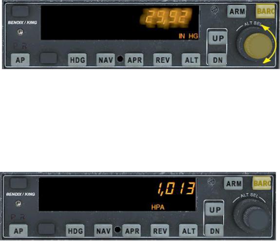
- Used to set the altitude alerter reference altitude; or may be used immediately after pressing the BARO button, to adjust the autopilot baro setting to match that of the airplane’s altimetermanual adjustment is whenrequired.
11. BARO SET (BARO) BUTTON
- When pushed and released, will change the display from the altitude alerter selected altitude to the baro setting display (either IN HG or HPA) for 3 seconds. If pushed and held for 2 seconds, will change the baro setting display from IN HG to HPA or vice versa. Once the baro setting display is visible the rotary knobs may be used to manually adjust the baro setting.
12. ALTITUDE ARM (ARM) BUTTON
- When pushed will toggle altitude arming on or off. When ALT ARM is annunciated, the autopilot will capture the altitude alerter displayed altitude (provided the aircraft is climbing or descending in VS to the displayed altitude). When the autopilot is engaged, ALT arming is automatic upon altitude alerter altitude selection via the rotary knobs. Note that the alerter functions are independent of the arming process thus providing full time alerting, even when the autopilot is disengaged.
13. ALTITUDE ALERTER/VERTICAL SPEED/BARO SETTING DISPLAY
- Normally displays the altitude alerter selected altitude. If the UP or DN button is pushed while in VS hold, the display changes to the command reference for the VS mode in FPM for 3 seconds. If the BARO button is pushed, the display changes to the autopilot baro setting in either IN HG or HPA for 3 seconds.
6
14. ALTITUDE ALERT (ALERT) ANNUNCIATION
- The ALERT annunciate is illuminated 1000 ft. prior to the selected altitude, extinguishes 200 ft. prior to the selected altitude and illuminates momentarily when the selected altitude is reached. Once the selected altitude is reached a flashing ALERT illumination signifies that the 200band”ft.has“safebeen exceededremain illuminated anduntil 1000willft. from the selected altitude. Associated with the visual alerting is an aural alert (5 short tones) which occurs 1000 feet from the selected altitude upon approaching the altitude and 200 feet from the selected altitude on leaving the altitude.
15. PITCH MODE DISPLAY
- Displays the active and armed pitch modes (VS, ALT, ARM, ALT and GS).
16. AUTOPILOT ENGAGED (AP) ANNUNCIATION
- Illuminates whenever the autopilot is engaged. Flashes during pilot initiated or automatic disengagement.
17. ROLL MODE DISPLAY
- Displays the active and armed roll modes (ROL, HDG, NAV ARM,NAV, APR ARM, APR, REV ARM,REV, GS ARM). Also displayed will be flashing AP annunciation (5 seconds) at each autopilot disconnect accompanied by an aural tone (for 2 seconds).
7
System Operating Modes
Functions independent of autopilot status
Altimeter setting
Upon successful completion of preflight test, the baro display will flash.
1. BARO setting - Enter barometric setting using the rotary knobs OR if correct as displayed, press BARO.
Note: triggering Barometric event (FS default key is B) will synchronize this unit’s baro setting with the Altimeter baro setting.
Baro unit conversion
The barometric pressure display can be toggled between IN HG and HPA as needed by the pilot.
1. BARO button - Press and hold for two seconds.
8
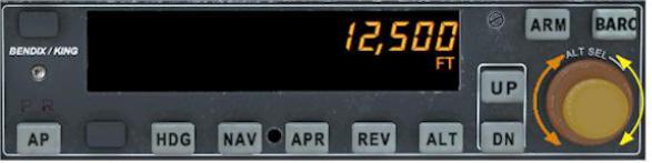
Altitude Alerter
1. ALTITUDE SELECT knob - ROTATE until the desired altitude is displayed. Outer knob for 1,000 ft. changes; inner knob for 100 ft. changes.
The ALERT annunciation is illuminated 1000 ft. prior to the selected altitude, extinguishes 200 ft. prior to the selected altitude and illuminates momentarily when the selected altitude is reached. Once the selected altitude is reached, a flashing ALERT illumination signifies that the 200 ft. exceeded“safeandband”will remain illuminatedhas beenuntil 1000 ft. from the selected altitude.
Associated with the visual alerting is an aural alert (five short tones) which occurs 1000 ft. from the selected altitude upon approaching the altitude and 200 ft. from the selected altitude on leaving the altitude.
9
System Operating Modes
ROLL functions available with autopilot engaged
Wing Leveler (ROL) Mode
In the roll mode, the autopilot maintains wings level flight.
1. Engage autopilot –Press and hold AP for 0.25 seconds to engage the autopilot. Note ROL, VS and current vertical speed is displayed. If no other modes are selected the autopilot will operate in the ROL and vertical speed hold modes.
Heading Select (HDG) Mode
In the heading mode, the autopilot will fly a selected heading.
10
 Loading...