


KT73
Table of contents
 Loading...
INSTALLATION MANUAL
KT 73
MODE S
TRANSPONDER
MANUAL NUMBER 006-10563-0000
REVISION 0 OCTOBER, 2002
Preliminary - Subject To Change Without Notice

WARNING
Prior to the export of this document, review for export license requirement is needed.
COPYRIGHT NOTICE
©2002 Honeywell International Inc.
Reproduction of this publication or any portion thereof by any means without the express written
permission of Honeywell is prohibited. For further information contact the manager, Technical
Publications, Honeywell, One Technology Center, 23500 West 105th Street Olathe KS 66061
telephone: (913) 782-0400.
Preliminary - Subject To Change Without Notice

BENDIX/KING KT 73
Rev 0, October/2002 10563I00.JA Page RH-1
REVISION HISTORY
KT 73 Installation Manual
Part Number: 006-10563-XXXX
For each revision, add, delete, or replace pages as indicated.
REVISION: Rev 0, October/2002
ITEM ACTION
New manual No previous manual revision exists.
Preliminary - Subject To Change Without Notice

BENDIX/KING KT 73
Rev 0, October/2002 10563I00.JA Page RH-2
THIS PAGE IS RESERVED
Preliminary - Subject To Change Without Notice

BENDIX/KING KT 73
Rev 0, October/2002 10563I00.JA Page TC-1
TABLE OF CONTENTS
SECTION I
GENERAL INFORMATION
PARAGRAPH PAG E
1.1 INTRODUCTION 1-1
1.2 EQUIPMENT DESCRIPTION 1-1
1.2.1 GENERAL DESCRIPTION 1-1
1.2.2 HARDWARE 1-1
1.2.3 FEATURES 1-2
1.3 TECHNICAL CHARACTERISTICS 1-3
1.3.1 KT 73 TECHNICAL CHARACTERISTICS 1-3
1.3.2 KT 73 RECEIVER CHARACTERISTICS 1-4
1.3.3 KT 73 TRANSMITTER CHARACTERISTICS 1-4
1.3.4 ANTENNA 1-5
1.4 UNITS AND ACCESSORIES SUPPLIED 1-6
1.4.1 CONFIGURATIONS AVAILABLE 1-6
1.4.2 KT 73 INSTALLATION KIT 1-6
1.5 ACCESSORIES REQUIRED, BUT NOT SUPPLIED 1-7
1.6 LICENSING REQUIREMENTS 1-8
1.7 INSTRUCTIONS FOR CONTINUED AIRWORTHINESS 1-8
SECTION II
INSTALLATION
PARAGRAPH PAG E
2.1 GENERAL INFORMATION 2-1
2.2 UNPACKING AND INSPECTING EQUIPMENT 2-1
2.3 EQUIPMENT INSTALLATION 2-1
2.3.1 GENERAL 2-1
2.3.2 AVIONICS COOLING REQUIREMENTS FOR PANEL MOUNTED EQUIPMENT 2-2
2.3.3 KT 73 INTERCONNECTION AND CABLE HARNESS FABRICATION 2-2
2.3.4 EQUIPMENT LOCATION 2-7
2.3.5 KT 73 INSTALLATION 2-8
2.3.6 MOLEX CONNECTOR ASSEMBLY PROCEDURE 2-9
2.3.7 POSITRONIC CONNECTOR ASSEMBLY PROCEDURE 2-10
2.4.1 TRANSPONDER SYSTEM CHECKOUT 2-51
Preliminary - Subject To Change Without Notice

BENDIX/KING KT 73
Rev 0, October/2002 10563I00.JA Page TC-2
SECTION III
OPERATION
PARAGRAPH PAG E
3.1 GENERAL 3-1
3.2 PROGRAMMING MODE 3-1
3.2.1 PROGRAMMABLE PARAMETERS 3-2
3.3 DETAILED OPERATING MODES 3-9
3.3.1 FUNCTIONAL MODES 3-9
3.3.2 FRONT PANEL OPERATION 3-15
3.3.3 BUILT IN TEST EQUIPMENT (BITE) 3-17
FIGURES
FIGURE PAG E
2-1 CRIMPING TOOLS (MOLEX) 2-11
2-2 CRIMPING TOOLS (POSITRONIC) 2-15
2-3 KT 73 PINOUT DIAGRAMS 2-19
2-4 KT 73 INSTALLATION DRAWING 2-23
2-5 SINGLE KT 73 BASIC INTERCONNECTION DRAWING 2-25
2-6 SINGLE KT 73 WITH TIS INTERCONNECTION DRAWING 2-27
2-7 SINGLE KT 73 WITH ADLP OR ADS-B INTERCONNECTION DRAWING 2-29
2-8 SINGLE KT 73 WITH SERIAL ALTITUDE INPUTS INTERCONNECTION
DRAWING 2-31
2-9 DUAL KT 73 BASIC INTERCONNECTION DRAWING 2-33
2-10 DUAL KT 73 WITH SERIAL ALTITUDE INPUTS INTERCONNECTION DRAWING 2-37
2-11 RF CONNECTOR DRAWING 2-43
2-12 ACCEPTABLE CABLE CONNECTIONS DRAWING 2-45
2-13 CABLE CONNECTOR DRAWING 2-47
2-14 TYPE “N” AND “C” CONNECTOR ASSEMBLY DRAWING 2-48
2-15 BNC CONNECTOR ASSEMBLY DRAWING 2-49
3-1 KT 73 FRONT PANEL 3-1
3-2 KT 73 CONFIGURATION MENU 3-3
3-3 KT 73 FIRST 4 OCTAL DIGITS OF THE AIRCRAFT ADDRESS 3-5
3-4 KT 73 LAST 4 OCTAL DIGITS OF THE AIRCRAFT ADDRESS 3-5
3-5 KT 73 LOWER AND UPPER MAXIMUM AIRSPEED 3-6
Preliminary - Subject To Change Without Notice

BENDIX/KING KT 73
Rev 0, October/2002 10563I00.JA Page TC-3
FIGURES (cont).
FIGURE PAG E
3-6 KT 73 STANDBY MODE 3-10
3-7 KT 73 GROUND MODE 3-10
3-8 KT 73 ON MODE 3-11
3-9 KT 73 ALTITUDE MODE 3-12
3-10 KT 73 FLIGHT ID MODE 3-13
3-11 KT 73 TEST MODE 3-13
TABLES
TAB LE PAG E
2-1 INSPECTION/CHECK PROCEDURE 2-51
2-2 RAMP TESTS 2-53
3-1 BITE FAULT CODES 3-18
Preliminary - Subject To Change Without Notice

BENDIX/KING KT 73
Rev 0, October/2002 10563I00.JA Page TC-4
THIS PAGE IS RESERVED
Preliminary - Subject To Change Without Notice

BENDIX/KING KT 73
Rev 0, October/2002 10563I00.JA Page 1-1
SECTION I
GENERAL INFORMATION
1.1 INTRODUCTION
This manual contains information relative to the physical, mechanical, and electrical characteris-
tics of the Honeywell KT 73 Mode S Transponder. Installation and operating procedures are also
included. Information relative to the maintenance, alignment, and procurement of the replacement
parts may be found in the KT 73 Maintenance/Overhaul Manual, P/N 006-15563-0000.
1.2 EQUIPMENT DESCRIPTION
1.2.1 General Description
The KT 73 General Aviation Mode S Transponder is designed to meet TSO-C112 for a Class 2A
ATCRBS/Mode Select Airborne Transponder System. It is a panel mounted transponder that ful-
fills the role of the airborne beacon equipment according to the requirements of the Air Traffic Ra-
dar Beacon System (ATCRBS). Its functionality includes replying to ATCRBS Mode A and C, In-
termode and Mode S interrogations as well as handling Comm A and B Mode S Data Link proto-
cols. The basic surveillance capability of the KT 73 satisfies the European Mode S mandate.
The KT 73 will pass Surveillance (UF 4 and 5) and Comm-A (UF 20 and 21) interrogations (minus
the 24 bit Aircraft Address) to the ADLP (Airborne Data Link Processor). It will also be capable of
receiving messages from the ADLP. It will also be capable of receiving messages from the ADLP
and sending the messages to the ground in Comm-B (DF 20 and 21) replies. The transponder/
ADLP will communicate using a RS-232 hardware interface and the RS-232 protocol developed
by Lincoln Labs. Other Mode S formats that the KT 73 can handle include Uplink Formats 0 and
11 and Downlink Formats 0, 4, 5, 11, 16, 17, and 18.
The KT 73 also provides Mode "C" or altitude reporting information. When the KT 73 is operated
in the "ALT" Mode and used in conjunction with an encoding altimeter, the flight level altitude is
displayed in addition to the 4096 code, and the altitude information is transmitted to the ground in
response to Mode "C" interrogations.
The Mode S function of the KT 73 will allow the ground station to individually select the aircraft by
its Aircraft Address assigned to the aircraft by the FAA.
When the "IDT" button is pressed, the current 4096 code and an additional special ident pulse are
transmitted by the KT 73 in response to a Mode A interrogation, to insure positive identification.
A test mode is also included in the KT 73 to confirm that the unit is operational.
The KT 73 implements the following DO-181C functions: Basic Transponder, Minimum Data Link
Transponder, and Extended Squitter Capability. The KT 73 implements its data link via an RS-
232 bus. The KT 73 does not support enhanced data link.
The KT 73 does not have full ELM capability and does not support Comm-D ELM protocol. The
KT 73 is not a TCAS-compatible transponder.
1.2.2 Hardware
The KT 73 features an all solid state transmitter with microprocessor control. Mode and Code se-
lection are performed by the rotary knobs, and all functions including flight level altitude, 4096
code, and aircraft address are presented on the gas discharge display. The KT 73 is derived from
the KT 70 Mode S transponder and will retrofit into KT 70, KT 71, and KT 76C installations.
The KT 73 has a Gas Discharge Display, Mode Select Knob, VFR pushbutton, Ident pushbutton,
and four ident code selector knobs.
Preliminary - Subject To Change Without Notice

BENDIX/KING KT 73
Rev 0, October/2002 10563I00.JA Page 1-2
The KT 73 has an Air/Ground discrete which, when connected to a strut switch on the aircraft, can
disable ATCRBS and Mode S All-Call replies when the aircraft is on the ground. A front panel
switch position, ’GND’, can also be used by the pilot instead of the strut switch.
1.2.3 Features
The KT 73 is capable of interfacing to the Traffic Information Service (TIS). This data link is intend-
ed to improve the safety and efficiency of “see and avoid” flight by providing the pilot automatic
display of nearby traffic and warnings of any potentially threatening conditions. The display of TIS
traffic requires a compatible MFD, currently the KMD 540. TIS is only provided within the service
volume of most Mode S terminal radar facilities and only in the contiguous United States (US).
The KT 73 is also capable of Automatic Dependent Surveillance - Broadcast (ADS-B) operation
which allows an aircraft or surface vehicle to transmit position, altitude, vector, and other informa-
tion for use by other aircraft, surface vehicles, or ground facilities. ADS-B requires a source of
GPS data, currently the KLN 94/KLN 900 are the only acceptable sources. The KT 73 has the
capability to transmit extended squitters and to operate in the Extended Squitter/Non Transponder
mode.
NOTE:
ADS-B is not currently operational but may be at a
later date.
The KT 73 has the ability to enter and display an 8-digit alpha-numeric Flight ID code. The Flight
ID information is entered by the pilot via front panel controls or is received from an ADLP. Flight
ID is selected for display from the front panel.
When the KT 73 receives Mode A interrogations from the ground radar facility, it will transmit a
coded group of pulses which consist of a four digit identification number that has been assigned
by the Air Traffic Controller. This code is entered into the KT 73 by the pilot and is transmitted
back to the ground as a Mode "A" reply. This coded information is presented on the ground radar
display at the appropriate range and azimuth. The Air Traffic Controller can then identify each air-
craft that is transponder equipped by its distinct coded number.
The VFR code, aircraft address, maximum air speed, display adjust, and installation parameters
can be programmed from the front panel of the KT 73 and stored in nonvolatile memory. Pilot ad-
justments include VFR code, Flight ID, and display brightness. Installation adjustments include
aircraft address, maximum airspeed, and configuration parameters (refer to Section 3 for specific
programming sequences). A configuration module is provided to store the address with the rack,
allowing units to be swapped from rack to rack without having to reprogram the aircraft address
or other configuration parameters.
NOTE:
The above features must be enabled via the pro-
gramming mode.
The flight ID information can be entered by the pilot via front panel controls. Flight ID can be se-
lected for display from the front panel.
The KT 73 has BITE (Built-In-Test-Equipment) which constantly monitors the operational health
of the unit. When a fault is detected, the transponder will display an error code on the front panel
display in order to help diagnose problems. When a critical fault is detected, the unit will turn on
an amber FAIL light on the front of the unit.
Preliminary - Subject To Change Without Notice

BENDIX/KING KT 73
Rev 0, October/2002 10563I00.JA Page 1-3
1.3 TECHNICAL CHARACTERISTICS
1.3.1 KT 73 TECHNICAL CHARACTERISTICS
NOTE:
All measurements are made with a 2.0 dB cable loss
at the antenna end.
TSO COMPLIANCE: SEE ENVIRONMENTAL QUALIFICATIONS APPENDIX
PHYSICAL DIMENSIONS: See figure 2-4
WEIGHT: See figure 2-4
APPLICABLE DOCUMENTS: TSO-C112 Class 2A ARINC 718-4
RTCA DO-181C ICAO DOC 9688-AN/952
RTCA DO-160D ICAO ANNEX 10, AMENDMENT 71
RTCA DO-178B RTCA DO-239
RTCA DO-260 EUROCAE ED-102
EUROCAE ED-14D EUROCAE ED-73A
MOUNTING: PANEL MOUNTED
TEMPERATURE:
-20
° C TO +55 ° C
Canadian cold soak tested to -35
° C
ALTITUDE RANGE: 51,500 FT
COOLING: NO FORCED-AIR COOLING REQUIRED,
BUT RECOMMENDED.
VIBRATION: DO-160D
CATEGORY S (CURVES B &M)
CATEGORY R (CURVE G)
ZONE 2
SHOCK: RIGID MOUNTING 6 G OPERATIONAL 20 G CRASH
SAFETY.
POWER INPUT: 35 WATTS (MAX)
1.25 A @ 27.50 V DC
2.50 A @ 13.75 V DC
Lighting Current
320 mA @ 14 V
160 mA @ 28 V
Preliminary - Subject To Change Without Notice

BENDIX/KING KT 73
Rev 0, October/2002 10563I00.JA Page 1-4
1.3.2 KT 73 RECEIVER CHARACTERISTICS
Sensitivity Variation with Frequency:
The RF input level required to produce 90% replies will not vary by more than 1 dB and will at no
time exceed a level of -69 dBm for standard ATCRBS interrogations in the frequency range be-
tween 1029.8 and 1030.2 MHz.
Bandwidth:
A standard ATCRBS interrogation signal required to trigger the transponder below 1005 MHz and
above 1055 MHz will be at least 60 dB stronger than that required to trigger the transponder at
1030 MHz with the same reply efficiency.
Sensitivity and Dynamic Range:
The minimum triggering level (MTL) is defined as the minimum input power level that results in a
90% reply ratio if the interrogation has nominal pulse characteristics.
A. The MTL for ATCRBS and ATCRBS/Mode S All- Call interrogations will be -73
dBm ± 4 dB.
B. The MTL for Mode S interrogations will be - 74 dBm ±3 dB.
C. The reply ratio will be at least 99% for all Mode S interrogations between MTL +3
dB and -21 dBm and at least 90% for ATCRBS and ATCRBS/Mode S All-Call in-
terrogations between MTL and -21 dBm.
D. The variation of MTL between ATCRBS Mode A and Mode C interrogations will not
exceed 1 dB.
ATCRBS, Mode S,ATCRBS/Mode S All-Call Low-Level Reply Ratio:
The reply ratio will not be more than 10% for interrogations at signal levels below -81 dBm.
L.O. Leakage:
L.O. level at 970 MHz will not exceed -73 dBm.
1.3.3 KT 73 TRANSMITTER CHARACTERISTICS
Reply Transmission Frequency:
The transmitter frequency of the reply will be 1090 ±1 MHz when observed into a 50 ohm load with
a VSWR of 1.5:1 or less.
Preliminary - Subject To Change Without Notice

BENDIX/KING KT 73
Rev 0, October/2002 10563I00.JA Page 1-5
RF Peak Power Output:
The transmitter output power will be 125 watts (21.0 dBW) peak power minimum and 500 watts
(27.0 dBW) peak power maximum at the terminals of the transponder antenna. The pulse ampli-
tude variation between any two pulses in an ATCRBS reply will not exceed 1 dB. A Mode S reply
will not contain a pulse amplitude variation, between any two pulses, of greater than 2 dB.
ATCRBS Reply Rate Capability:
The transponder will be able to continuously generate at least 500 ATCRBS 15-pulse replies per
second and will have the capability of a peak reply rate of 1,200 ATCRBS 15-pulse replies for a
duration of 100 ms.
NOTE:
A 15-pulse reply includes 2 framing pulses, the 12 in-
formation pulses, and the SPI pulse.
Mode S Reply Rate Capability:
The transponder will have the capability of generating the following reply rates for short Mode S
downlink formats:
A. 50 Mode S replies in a 1 second interval.
B. 18 Mode S replies in a 100 ms interval.
C. 8 Mode S replies in a 25 ms interval.
D. 4 Mode S replies in a 1.6 ms interval.
The transponder will have the capability of generating the following reply rates for long Mode S
downlink formats:
A. At least 16 of the 50 Mode S replies in any 1 second interval.
B. At least 6 of the 18 Mode S replies in a 100 msec interval.
C. At least 4 of the 8 Mode S replies in a 25 msec interval.
D. At least 2 of the 4 Mode S replies in a 1.6 msec interval.
Unwanted Output Power:
The RF output power at 1090 MHz ±3 MHz, at the RF output of the transponder, will not exceed -
50 dBm when the transmitter is in the inactive state. The inactive state is defined to include the
entire period between ATCRBS and/or Mode S transmissions less 10 µsec transition periods, if
necessary, preceding and following the extremes of the transmission.
1.3.4 ANTENNA
Any L-Band blade antenna is suitable for use with the KT 73 provided it is certified to TSO-C74c.
Preliminary - Subject To Change Without Notice

BENDIX/KING KT 73
Rev 0, October/2002 10563I00.JA Page 1-6
1.4 UNITS AND ACCESSORIES SUPPLIED
1.4.1 CONFIGURATIONS AVAILABLE
P/N 066-01164-0101 is the only version of the KT 73 that is currently available. Included with the
KT 73 is the mounting rack and the configuration module. The configuration module is optional
but is strongly suggested. With the module, the installation unique configuration is maintained if
a different KT 73 is swapped into the aircraft.
1.4.2 KT 73 INSTALLATION KIT
The KT 73 Transponder installation kit P/N 050-03451-0000 contains the following parts:
050-03451-0000 INSTALL KIT KT 73 Rev. B
---------------------------------------------------------------
SYMBOL PART NUMBER FIND NO DESCRIPTION UM -0000
---------------------------------------------------------------
030-00101-0002 PANEL MOUNT PLUG EA 1.00
030-01094-0002 CONNECTOR 12/24 P EA 1.00
030-01096-0000 KEY POLARIZER EA 1.00
030-01107-0024 CONNECTOR TERM 24T EA 1.00
030-01407-0000 CONTACT FEMALE EA 7.00
030-03454-0002 CONN, RECT, RECPT, EA 1.00
057-05944-0024 KT 73 INSTALL KIT EA 1.00
089-02013-0037 NUT FLAT 6-32 EA 3.00
089-02147-0022 NUT LOCK 6-32 EA 2.00
089-02353-0001 NUT CLIP 6-32 EA 6.00
089-05903-0007 SCR PHP 4-40X7/16 EA 2.00
089-05907-0006 SCR PHP 6-32X3/8 EA 1.00
089-06012-0008 SCR FHP 6-32X1/2 EA 6.00
089-08016-0037 WSHR INTL LK #6 EA 2.00
089-08027-0030 WSHR FLT STD #6 EA 1.00
089-08094-0030 WSHR FLT STD .446 EA 1.00
089-08110-0034 WSHR SPLT LK #6 EA 1.00
089-08168-0002 WASHER WAVE EA 1.00
090-00019-0007 RING RTNR .438 EA 1.00
091-00031-0005 NY CA CLAMP .312 EA 1.00
155-06046-0000 INSTALLATION DWG RF .00
Preliminary - Subject To Change Without Notice

BENDIX/KING KT 73
Rev 0, October/2002 10563I00.JA Page 1-7
1.5 ACCESSORIES REQUIRED, BUT NOT SUPPLIED
The following parts are recommended for a cable setup with dimensions of 4.5 feet to 11 feet:
(See Figure 2-12, Sheet 1 of 2).
The following parts are recommended for a cable setup with dimensions of 10 feet to 25 feet:
(See Figure 2-12, Sheet 2 of 2).
The following parts are recommended for a cable setup with dimensions of 16 feet to 32 feet (See
Figure 2-12, Sheet 2 of 2):
Honeywell PART NUMBER DESCRIPTION QUANTITY
030-00101-0002 Connector, Coax 1
024-00051-0060 Cable,Coax 11 ft.
030-00005-0000 Connector, Coax Mod Type BNC 1
Honeywell PART NUMBER DESCRIPTION QUANTITY
030-00102-0001 Connector, Type Unit 1
024-00072-0000 Cable,Coax 25 ft.
030-00435-0000 Connector, Antenna 1
Honeywell PART NUMBER DESCRIPTION QUANTITY
030-00101-0002 Connector Type Unit 1
024-00051-0060 Cable, Coax 6 in.
024-00071-0000 Cable, Coax 32.5 ft.
030-00138-0000 Connector, Unit extension to antenna connector 6 in.
030-00434-0000 Connector, Antenna 2
Preliminary - Subject To Change Without Notice

BENDIX/KING KT 73
Rev 0, October/2002 10563I00.JA Page 1-8
1.6 LICENSING REQUIREMENTS
For US registered aircraft, the transmitter, as installed in the aircraft, requires an Aircraft Radio
Station License. This license is obtained by filing the FCC Form 404. While awaiting the receipt
of the station license, a copy of FCC Form 404 must be kept in the aircraft.
This equipment has been type accepted by the FCC and entered on the type accepted equipment
list, as FCC ID: ASYKT73 and must be identified as FCC ID: ASYKT73 on your Form 404, Aircraft
Radio Station License application.
For non-US registered aircraft, follow applicable licensing requirements as required.
1.7 INSTRUCTIONS FOR CONTINUED AIRWORTHINESS
The instructions for continued airworthiness given in the TC or STC approvals for this product sup-
plements or supersedes the instructions for continued airworthiness in this manual.
Most Honeywell products are designed and manufactured to allow "on condition maintenance."
On condition maintenance is described as follows; There are no periodic service requirements
necessary to maintain continued airworthiness. No maintenance is required until the equipment
does not properly perform its intended function. When service is required, a complete perfor-
mance test should be accomplished following any repair action. Consult the appropriate unit
Maintenance/Overhaul Manual for complete performance test information.
Preliminary - Subject To Change Without Notice

BENDIX/KING KT 73
Rev 0, October/2002 10563I00.JA Page 2-1
SECTION II
INSTALLATION
2.1 GENERAL INFORMATION
This section contains suggestions and factors to consider before installing the KT 73 Mode S Tran-
sponder. Close adherence to these suggestions will assure a more satisfactory performance from
the equipment.
The conditions and tests required for TSO approval of this article are minimum performance stan-
dards. It is the responsibility of those desiring to install this article either on or within a specific
type or class of aircraft to determine that the aircraft installation conditions are within TSO stan-
dards. The article may be installed only if further evaluation by the applicant documents an ac-
ceptable installation and is approved by the Administrator.
2.2 UNPACKING AND INSPECTING EQUIPMENT
Exercise extreme caution when unpacking the unit. Make a visual inspection of the unit for evi-
dence of damage incurred during shipment. If a claim for a damage is to be made, save the ship-
ping container to substantiate the claim. When all equipment is removed, place all packing mate-
rials in the shipping container for future storage or reshipment of the unit.
2.3 EQUIPMENT INSTALLATION
2.3.1 GENERAL
The following paragraphs contain information pertaining to the initial installation of the KT 73 Mode
S Transponder, including instructions concerning the location and mounting of the supporting an-
tenna.
The equipment should be installed in the aircraft in a manner consistent with acceptable workman-
ship and engineering practices and in accordance with the instructions set forth in this publication.
To ensure that the system has been properly and safely installed in the aircraft, the installer should
make a through visual inspection and conduct an overall operational check of the system on the
ground prior to flight.
CAUTION:
AFTER INSTALLATION OF THE CABLING
AND BEFORE INSTALLATION OF THE
EQUIPMENT, A CHECK SHOULD BE MADE
WITH THE AIRCRAFT PRIMARY POWER
SUPPLIED TO THE MOUNTING CONNEC-
TOR TO ENSURE THAT POWER IS APPLIED
ONLY TO THE PINS SPECIFIED IN THE IN-
TERCONNECTION DRAWINGS, FIGURES 2-
5 THRU 2-10.
The installation should be installed in accordance with standards established by the customer’s
installing agency and existing conditions as to unit location and type of installation. However, the
following suggestions should be considered before installing the system. Close adherence to
these suggestions will assure a more satisfactory performance from the equipment. The installing
agency will supply and fabricate all external cables. The connectors required are supplied by Hon-
eywell.
Preliminary - Subject To Change Without Notice

BENDIX/KING KT 73
Rev 0, October/2002 10563I00.JA Page 2-2
NOTE:
The TSO identifies the minimum performance stan-
dards, tests, and other conditions applicable for issu-
ance of design and production approval of the arti-
cle. The TSO applicant is responsible for document-
ing all limitations and conditions suitable for installa-
tion of the article. An applicant requesting approval
for installation of the article within a specific type or
class of product is responsible for determining envi-
ronmental and functional compatibility.
2.3.2 AVIONICS COOLING REQUIREMENTS FOR PANEL MOUNTED EQUIPMENT
The greatest single contributor to increased reliability of all modern day avionics is to limit the max-
imum operating temperature of the individual units whether panel or remote mounted. While mod-
ern day individual circuit designs consume much less electrical energy, the watts per cubic inch
dissipated within avionics units remains much the same because of high density packaging tech-
niques utilized. Consequently, the importance of providing avionics stack cooling is essential to
the life span of the equipment.
While each individual unit may not require forced air cooling, the combined heat load of several
units operating in a typical avionics stack will significantly degrade the reliability of the avionics if
provisions for stack cooling are not incorporated in the initial installation. Recommendations on
stack cooling are contained in Honeywell Installation Bulletin #55. Failure to provide stack cooling
will certainly lead to increased avionics maintenance costs and may void the warranty.
2.3.3 KT 73 INTERCONNECTION AND CABLE HARNESS FABRICATION
2.3.3.1 General
The KT 73 Mode S Transponder receives primary power from the aircraft power source. Power
connections, voltage requirements, and circuit breaker requirements are shown on the intercon-
nect diagrams (Figures 2-5 through 2-10).
The length of the wires to parallel pins should be approximately the same length, so that the best
distribution of current can be effected. Honeywell recommends that all wires, including spares as
shown on the interconnect diagram be included in the fabrication of the wiring harness. However;
if full wiring is not desired, the installer should ensure that the minimum wiring requirements for
the features and functions to be used have been incorporated.
When cables are installed in the aircraft, they must be supported firmly enough to prevent move-
ment and should be carefully protected against chaffing. Additional protection should also be pro-
vided in all locations where the cable may be subjected to abuse.
In wire bundles, the cabling should not be tied tightly together as this tends to increase the possi-
bility of noise pickup and similar interference. When routing cables through the aircraft the cables
should cross high level rf lines at right angles.
Prior to installing any equipment, make a continuity check of all wires and cables associated with
the system. Then apply power and check for proper voltages at system connectors, and then re-
move power before completing the installation.
The following guidelines are recommended:
(1) The installing facility will supply and fabricate all external cables (see figures 2-1
through 2-3, 2-5 through 2-15). The required connectors are supplied as part of the
installation kit (P/N 050-03451-0000).
Preliminary - Subject To Change Without Notice

BENDIX/KING KT 73
Rev 0, October/2002 10563I00.JA Page 2-3
(2) The KT 73 must be kept a minimum of three feet from the antenna. Additionally, the
antenna coax cable should not be bundled with the other wiring harnesses to the KT
73.
(3) The length and routing of the external cables must be carefully planned before at-
tempting the actual installation. Avoid sharp bends or locating the cable near aircraft
control cables. The cables should be of a length to allow for a “maintenance loop”.
That is, the length should be adequate to access and extend the connectors aft of
the panel for future maintenance purposes. Excess cabling should be secured and
stowed by tie-wrapping until such maintenance is required.
(4) The cables should be supported firmly enough to prevent movement. They should
be carefully protected wherever one may chafe against another or against some oth-
er object. Extra protection should be provided in all locations where the cables may
be subject to abuse. Shields on shielded wires should be grounded as shown on
the system interconnection diagrams.
(5) Shields should be carried through any obstruction via a thru-bulkhead connector. If
shielding cannot be carried through by use of a bulkhead/connector pin, precautions
should be taken to ensure each segment of the shielded lead be grounded at only
one point. A ground connection of not more than two inches in length should be
used. The preceding discussion does not apply to coaxial and quadraxial cable.
(6) Avoid routing cabling near high noise and high power sources.
(7) Do not route the transponder antenna coax near ADF sense or loop antenna cables.
NOTE:
The total losses in the coaxial cable run and inter-
connects between the antenna and the KT 73 tran-
sponder must not be less than 1 dB and must not be
more than 2.1 dB at 1030MHz. Use Figures 2-5
through 2-10 as a reference and adhere
to the di-
mensions prescribed in Figure 2-13.
2.3.3.2 Primary Power and Circuit Breaker Requirements and Wiring
The KT 73 transponder receives primary power from the aircraft power circuit breakers. The KT
73 is designed to operate over the range of 11-33V dc. Power connections, wire sizes, and circuit
breaker requirements are shown on the interconnection diagrams Figures 2-5 through 2-10.
2.3.3.3 Functional Pinout Descriptions
This section gives a brief description of the inputs and outputs of the KT 73 (refer also to figure -
2-3). It is provided so that the installer can determine what aircraft specific wiring requirements
are needed in order to install the unit. Unless otherwise specified, pins not used are to be left
open.
Preliminary - Subject To Change Without Notice

BENDIX/KING KT 73
Rev 0, October/2002 10563I00.JA Page 2-4
Main Connector - JKT73-1
Pin 1; AIRCRAFT GROUND
This pin provides an internal connection to chassis and may be used as the third wire
for RS-232 busses.
Pin 2; +14 V DC LIGHTING
+14 VDC lighting (320mA ± 32 mA) Open for +28 V DC lighting.
Pin 3; +28 V DC LIGHTING
+28 VDC lighting (160mA ± 16 mA). Ground for +14 V DC lighting.
Pin 4; ARINC SUPPRESSION I/O
As an input, a voltage ≥ 18 V and ≤ 70 V will cause suppression. A steady state voltage
≥ 18 V will cease suppression. As an output, this pin will go ≥ 18 V when the
transponder transmits. This pin conforms to ARINC 718A Attachment 6.
Pin 5; EXTERNAL AIR/GROUND
GND (<10 ohms) on this pin will inhibit ATCRBS replies and replies to Mode S All Call
messages.
Pin 6; TIS 429 TX B
This line is half of a standard differential ARINC 429 output used to broadcast traffic
information services to a display.
Pin 7; RS232 ALT RX
This line is programmable as the receive line of an RS-232 port used to report altitude.
Pin 8; GILLHAM ALTITUDE D4/RS232 ALT TX
This line is programmable as a Gillham altitude input or as the transmit line of an
RS-232 port used to report altitude. As a Gillham input, HIGH = voltage > 18.5 VDC
or resistance-to-ground > 100KΩ. Per ARINC 572, Attachment 4, input is an active
LOW pulse where LOW = voltage < 2.0 volts or resistance-to-ground < 15 KΩ.
Pin 9; 9 V SUPPRESSION IN
This line is a 9V Suppression Input. Voltage ≥ 5 will suppress. Voltage < 3.5V or an
open will not suppress the transponder.
Pin 10; EXTERNAL STANDBY~
GND (<10 ohms) on this pin will prevent replies and squitters.
Pin 11; 11 - 33 V DC
Aircraft Power
Pin 12; 11 - 33 V DC
Aircraft Power
Pin A; AIRCRAFT GROUND
This pin provides an internal connection to chassis and may be used as the third wire
for RS-232 busses.
Pin B; GILLHAM ALTITUDE B4/RS232 GPS RX
This line is programmable as a Gillham altitude input as defined for pin 8 or as the
receive line of an RS-232 port used to receive GPS information to support ADS-B.
Pin C; GILLHAM ALTITUDE B2/RS232 GPS TX
This line is programmable as a Gillham altitude input as defined for pin 8 or as the
transmit line of an RS-232 port used to receive GPS information to support ADS-B.
Preliminary - Subject To Change Without Notice

BENDIX/KING KT 73
Rev 0, October/2002 10563I00.JA Page 2-5
Pin D; GILLHAM ALTITUDE C1/ARINC429 RX 0B
This line is programmable as a Gillham altitude input as defined for pin 8 or as the
receive line of an ARINC 429 port used to report altitude.
Pin E; GILLHAM ALTITUDE B1/ARINC429 RX 0A
This line is programmable as a Gillham altitude input as defined for pin 8 or as the
receive line of an ARINC 429 port used to report altitude.
Pin F; EXTERNAL IDENT~
GND (<10 ohms) will initiate IDENT sequence. HIGH = resistance-to-ground > 100KΩ
(inactive IDENT).
Pin H; GILLHAM ALTITUDE C4/RS485 RX B
This line is programmable as a Gillham altitude input as defined for pin 8 or as the
receive line reserved for a future interface.
Pin J; GILLHAM ALTITUDE A4/RS485 RX A
This line is programmable as a Gillham altitude input as defined for pin 8 or as the
receive line reserved for a future interface.
Pin K; GILLHAM ALTITUDE A2/RS485 TX B
This line is programmable as a Gillham altitude input as defined for pin 8 or as the
transmit line reserved for a future interface.
Pin L; GILLHAM ALTITUDE C2/RS485 TX A
This line is programmable as a Gillham altitude input as defined for pin 8 or as the
transmit line reserved for a future interface.
Pin M; GILLHAM ALTITUDE A1
This line is programmable as a Gillham altitude input as defined for pin 8.
Pin N; TIS 429 TX A
Standard ARINC 429 output used to broadcast traffic information services to a display.
Auxiliary Connector - JKT73-2
Pin 1; EXTERNAL EEPROM CS
Voltage ≥ 2.0 VDC selects external EEPROM.
Pin 2; EXTERNAL EEPROM
Voltage ≥ 2.0 VDC indicates external EEPROM is available.
Pin 3; AUDIO HI
Message audio output.
Pin 4; +5 V DC
This pin provides +5 VDC ± 0.3 VDC out to power external EEPROM.
Pin 5; AUDIO LO
Message audio output.
Pin 6; AUDIO INHIBIT
Mutes audio with input of <3.0 V DC or < 10 ohms. Input > 100 K ohms will not mute.
Pin A; SERIAL DATA OUT
Used by microprocessor to write data to external EEPROM.
Pin B; SERIAL DATA IN
Used by microprocessor to read data from external EEPROM.
Preliminary - Subject To Change Without Notice

BENDIX/KING KT 73
Rev 0, October/2002 10563I00.JA Page 2-6
Pin C; SERIAL CLOCK
Used by microprocessor to provide serial clocking for pins A and B.
Pin D; AIRCRAFT GROUND
This pin provides an internal connection to chassis and may be used as the third wire
for RS-232 busses.
Pin E; ARINC429 RX 1A/RS232 RX
Programmable line to receive ARINC 429 TIS control or provide RS-232 RX input for
either ADLP or ADS-B.
Pin F; ARINC429 RX 1B/RS232 TX
Programmable line to receive ARINC 429 TIS control or provide RS-232 TX output for
either ADLP or ADS-B.
Antenna Connector - JKT73-3
Pin 1; RF RX/TX PORT
Receive at 1030 MHz ± 0.01 MHz; Transmit at 1090 MHz ± 1.00 MHz.
External Connector - JKT73-4
Pin A; AUDIO INHIBIT
Mutes audio with input of <3.0 V DC or < 10 ohms. Input > 100 K ohms will not mute.
This input is designed for installations including an EGPWS system. In that case, the
Audio Out discrete of the EGPWS must be connected to this pin.
Pin B; AIRCRAFT GROUND
This pin provides an internal connection to chassis and may be used as the third wire
for RS-232 busses.
Pin C; ARINC429 RX 1A/RS232 RX
Programmable line to receive ARINC 429 TIS control or provide RS-232 RX input for
either ADLP or ADS-B.
Pin D; ARINC429 RX 1B/RS232 TX
Programmable line to receive ARINC 429 TIS control or provide RS-232 TX output for
either ADLP or ADS-B.
Pin E; AUDIO HI
Message audio output.
Pin F; AUDIO LO
Message audio output.
Preliminary - Subject To Change Without Notice

BENDIX/KING KT 73
Rev 0, October/2002 10563I00.JA Page 2-7
2.3.4 EQUIPMENT LOCATION
Care should be exercised to avoid mounting components near equipment operating with high
pulse current or high power outputs such as radar and satellite communications equipment. In
general, the equipment should be installed in a location convenient for operation, inspection, and
maintenance, and in an area consistent with the TSO environmental limits.
Refer to the mechanical installation drawing (figure 2-4), cable and connector assembly diagrams
(figures 2-1, 2-2, 2-11 through 2-15, interconnection drawings (figures 2-5 through 2-10), and con-
nector pin assignments diagrams (figure 2-3) as required. Determine the mounting location for
system components following the guidelines below.
2.3.4.1 Transponder And Mounting Tray Locations
The tray-mounted KT 73 Mode S Transponder can be installed in any convenient location on the
panel that is free from excessive heat and vibration and which provides reasonable access for in-
spection and maintenance. To achieve maximum performance, the KT 73 should be installed ad-
jacent to other receivers with similar functions.
To allow for inspection or repair of the wiring of the connector assembly itself, sufficient lead length
should be left so that when the mounting hardware for the rear connectors and antenna coaxial
cable is removed the assembly may be pulled forward several inches. Also, a bend should be
made in the harness (at the rear connectors) to allow water droplets that might form on the har-
ness due to condensation, to drip off at the bend and not collect in the connection.
Except for antenna cables, (see Figure 2-12) the lengths of the cables from the KT 73 transponder
mounting tray connector to other system units are not critical because unit interfaces are designed
with high impedance inputs, low impedance outputs, and low noise susceptibility characteristics.
Forced air cooling is recommended but is not a requirement. Outline drawing Figure 2-4 shows
transponder and mounting tray dimensions.
2.3.4.2 Antenna
The antenna should be well removed from other antenna projections, the engine(s), and propel-
ler(s). It should also be well removed from landing gear doors, access doors, or other openings
which will break the ground plane for the antenna. The surface directly beneath the antenna
should be a flat plane over as large an area as possible.
A back-up plate should be used for added strength on thin-skinned aircraft.
To prevent rf interference, the antenna must be physically mounted a minimum distance of three
feet from the KT 73 and the wiring harness.
The transponder antenna should be mounted a minimum of six feet away from the DME antenna
and four feet from the ADF sense antenna.
Where practical, plan the antenna location to keep cable lengths as short as possible and avoid
sharp bends in the cable to minimize the VSWR.
Avoid running other cables or wires near the antenna cable.
On pressurized aircraft, the antenna should be sealed using RTV No. 3145 (P/N 016-01082-0000)
or equivalent around the connector and mounting hardware.
The antenna mounting should be sealed from the outside for moisture protection using RTV or
equivalent.
Mount the antenna in as clean as environment as possible, away from exhaust gases and oils.
The antenna should be kept clean. If left dirty (oil covered), the range of the transponder may be
affected.
Preliminary - Subject To Change Without Notice

BENDIX/KING KT 73
Rev 0, October/2002 10563I00.JA Page 2-8
2.3.5 KT 73 INSTALLATION
The mounting tray for the transponder should be mounted using the dimensions specified in the
outline and mounting drawing, Figure 2-4. The mounting tray should be wired according to the
system interconnect diagram, Figure 2-5 through 2-10.
2.3.5.1 Retrofit into existing KT 70, KT 71, and KT 76C Installations
If the KT 73 is replacing an existing KT 70, KT 71, or KT 76C without adding new functionality such
as TIS, ADLP, or ADS-B, the KT 73 may simply be installed in the existing rack, provided that the
installation is in a fixed wing aircraft. If the installation is in a rotary wing aircraft, the existing rack
will have to be replaced with a new rack. If the new rack in installed, it is suggested that a new
configuration module be used even if the existing installation did not have one. The KT 73 must
be programmed per section 3.2.
2.3.5.2 New Transponder Tray Installations
(1) Rear connector wiring must be completed before permanently fastening the mount-
ing tray to the panel.
(2) Remove the panel area specified on the outline and mounting drawing (see Figure
2-4) for front and rear dimensions. Care must be taken to avoid damage to the ad-
jacent equipment and cables.
(3) Secure the tray to the panel. The mounting tray must be secured in the rear by at-
taching the tray to a structural member of the airframe.
(4) Look at the bottom of the unit and confirm the front lobe of the hold-down device is
in a vertical position. This can be accomplished by using a 3-32 inch Allen wrench
through the front plate.
2.3.5.3 Transponder
(1) Slide the transponder into the tray until the front lobe touches the mounting tray.
(2) Turn the Allen wrench clockwise until the rear lobe engages the mounting tray slot.
Continue turning the wrench clockwise until tight.
(3) For removal, turn the 3-32 inch Allen wrench counter-clockwise until the unit disen-
gages from the mounting tray slot. The unit can now be pulled completely out.
CAUTION:
DO NOT OVERTIGHTEN THE LOCKING FASTENER
2.3.5.4 Aircraft Address Programming Options
The Mode S aircraft address and maximum airspeed data must be programmed for use by the KT
73. In installations having an external EEPROM module (also referred to as a Configuration Mod-
ule), this information is contained in that module as well as in the memory internal to the KT 73.
In these cases, the data in the external Configuration Module will automatically be copied into the
internal memory of any KT 73 plugged into the rack. This assumes that the external module has
been previously programmed by a KT 73 as described elsewhere in this manual.
Data that has been programmed into an external Configuration Module as part of a KT 70 instal-
lation will be automatically replaced by data contained in the internal memory of the KT 73. All
new installations will have a Configuration Module as these installations use a new rack (P/N 200-
10069-0000) which includes the Configuration Module.
Preliminary - Subject To Change Without Notice

BENDIX/KING KT 73
Rev 0, October/2002 10563I00.JA Page 2-9
In retrofit installations where a Configuration Module does not exist, the KT 73 will recognize this
condition and operate from the data contained in the internal memory. In this arrangement, the
configuration data will be lost when the KT 73 is replaced with a different unit, such as a loaner,
and must be re-entered.
NOTE:
THE AIRCRAFT MODE S ADDRESS MUST BE OB-
TAINED FROM FAA AND PROGRAMMED INTO
THE KT 73 OR EXTERNAL ADDRESS EEPROM.
FOR US REGISTERED AIRCRAFT, THE ICAO
AIRCRAFT ADDRESS CODE CAN BE FOUND ON
THE AIRCRAFT REGISTRATION.
AIRCRAFT MODE S ADDRESSES MAY BE OB-
TAINED BY CALLING THE FAA AIRMAN AND AIR-
CRAFT REGISTRY DIVISION AT (405)-954-3116.
IF THREE (3) OR MORE ADDRESSES ARE NEED-
ED, WRITE TO AIRCRAFT REGISTRATION
BRANCH, ANV-450, P.O. BOX 25082, OKLAHOMA
CITY, OK 73125.
To program the aircraft address and/or the maximum air speed please refer to Section 3.2.
2.3.5.5 Antenna
For L-band blade antenna outline drawing, installation procedures, and mounting dimensions, re-
fer to the manufacturer’s instructions.
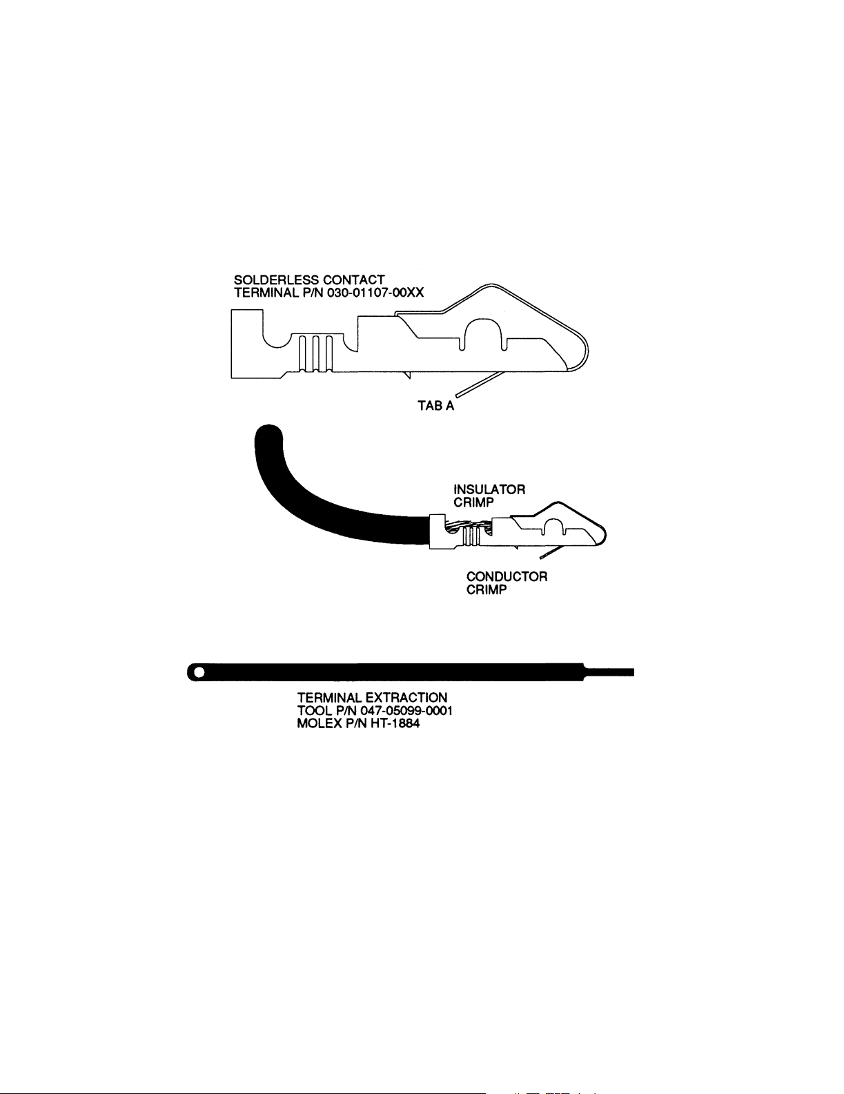
2.3.6 MOLEX CONNECTOR ASSEMBLY PROCEDURE
The KT 73 uses a special connector that mates directly with the printed circuit board inside the
unit (see Figure 2-1). Assemble the connector using the following procedure:
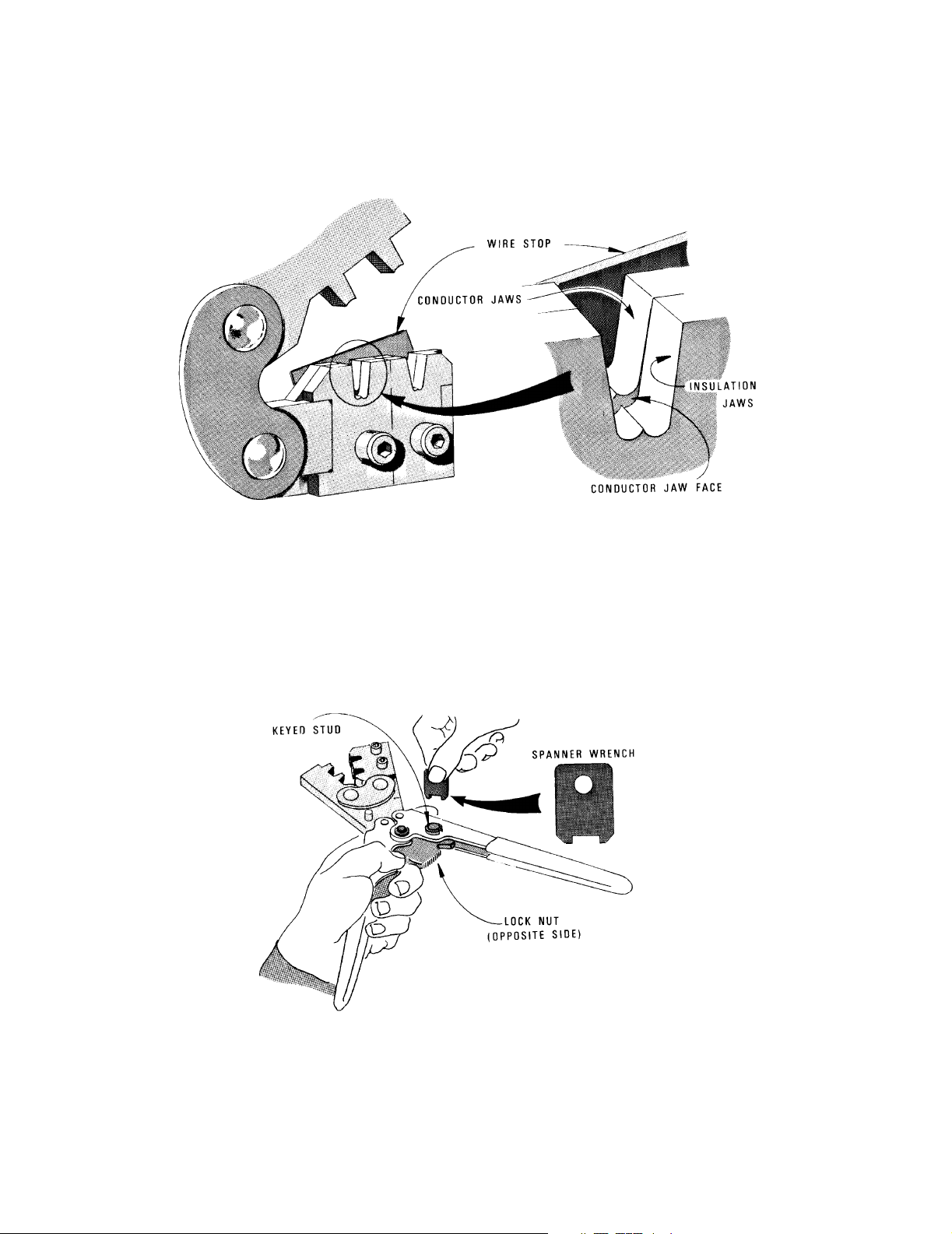
2.3.6.1 Solderless Contact Terminal Assembly using Molex Crimper
Refer to instructions in Figure 2-1.
2.3.6.2 Solderless Contact Terminal Assembly using Pliers
(1) Strip each wire 5/32 inches for contact terminal (P/N 030-01107-0024). The last two
digits of the contact terminal part number indicates the number of terminals fur-
nished.
(2) Tin the exposed conductor.
(3) Using needle nosed pliers, fold over each conductor tab, in turn, onto the exposed
conductor. when both tabs have been folded, firmly press the tabs against the con-
ductor.
(4) Repeat step (3) for insulator tabs.
(5) Apply a small amount of solder (using minimum heat) to the conductor/tab connec-
tion to assure a good electro-mechanical joint.
Preliminary - Subject To Change Without Notice

BENDIX/KING KT 73
Rev 0, October/2002 10563I00.JA Page 2-10
2.3.6.3 Contact Insertion into Molex Connector Housing
(1) After the contact terminals have been installed on the wiring harness, the contact
terminals can be inserted into the proper location in the connector housing (P/N 030-
01094-0066). The terminal cannot be inserted upside down. Be sure to push the
terminal all the way in, until a click can be heard or felt.
(2) The self-locking feature can be tested by gently pulling on the wire.
2.3.6.4 Extraction of Contact from Molex Connector
(1) Slip the flat narrow blade of a Molex contact ejector tool, HT-1884 (Honeywell P/N
047-05099-0001), under the contact on the mating side of the connector. By turning
the connector upside down one can see the blade slide to the stop.
(2) When the ejector is positioned against the stop the locking key of the contact is
raised, allowing the contact to be removed by pulling moderately on the lead.
(3) Neither the contact or position is damaged by removing a contact; however, the con-
tact should be checked visually before reinstalling in connector, to be certain that re-
taining tab "A" extends as shown (see Figure 2-1) for retention in connector.
2.3.7 POSITRONIC CONNECTOR ASSEMBLY PROCEDURE
Assemble the Positronic connector using the procedures detailed in figure 2-2.
Preliminary - Subject To Change Without Notice
BENDIX/KING KT 73
Rev 0, October/2002 10563I00.JA Page 2-11
FIGURE 2-1 CRIMPING TOOLS (MOLEX)
(Sheet 1 of 3)
Preliminary - Subject To Change Without Notice

BENDIX/KING KT 73
Rev 0, October/2002 10563I00.JA Page 2-12
FIGURE 2-1 CRIMPING TOOLS (MOLEX)
(Sheet 2 of 3)
Preliminary - Subject To Change Without Notice
BENDIX/KING KT 73
Rev 0, October/2002 10563I00.JA Page 2-13
Once the terminal is in the correct position, close the jaws gently until the terminal is held loosely in place. Push the wire
stop down so that it rests snugly behind the contact portion of the terminal.
Strip off 1/8 inch of the wire insulation and insert the wire through the insulation tabs into the conductor tabs until the insu-
lation hits the conductor jaw face or until the conductor touches the wire stop.
Squeeze the handles until the crimp jaws close and the ratchet releases.
Straighten the terminal if necessary, then release the plier grips and remove the crimped terminal.
CRIMPING PRESSURE ADJUSTMENT
If too much or too little pressure is needed to release the crimper’s ratchet pawl at the end of the crimp stroke, the ratchet
can be easily adjusted. A spanner wrench provided with the tool can be used to loosen the lock nut, and rotate the keyed
stud clockwise for increased pressure and counter-clockwise for decreased pressure. Once the desired pressure has been
set, the lock nut must be tightened again. Newer models may have a screwdriver adjustment.
FIGURE 2-1 CRIMPING TOOLS (MOLEX)
(Sheet 3 of 3)
Preliminary - Subject To Change Without Notice
Loading...