


HZ432 TrueZONE
Zone Panel Professional Installation Guide
69-2198-01
Installation Guide |
|
Table of Contents |
|
Specifications................................................................................................................................. |
ii |
Accessories..................................................................................................................................... |
1 |
Mounting......................................................................................................................................... |
2 |
Wiring.............................................................................................................................................. |
3 |
Heat Pump...................................................................................................................................... |
6 |
Dual Fuel......................................................................................................................................... |
8 |
Basic Configuration...................................................................................................................... |
10 |
Advanced Configuration.............................................................................................................. |
12 |
Operation...................................................................................................................................... |
13 |
Checkout....................................................................................................................................... |
13 |
Warranty........................................................................................................................................ |
14 |
Specifications |
|
Input Ratings:
Voltage: 18-30 VAC 50/60 Hz transformer of 40 VA or more.
Current Draw:
Zone Panel: 8.5 VA max.
All VA specifications at 24 VAC.
Wiring:
18or 20-gauge solid (not stranded) wire.
Humidity Ratings:
5% to 90% RH non-condensing.
Temperature Ratings:
Shipping: -20° to 150°F (-29° to 66°C) Operating: -40° to 165°F (-40° to 74°C)
Dimensions:
See below.
Emissions:
Complies with FCC Class B, part 15 requirements.
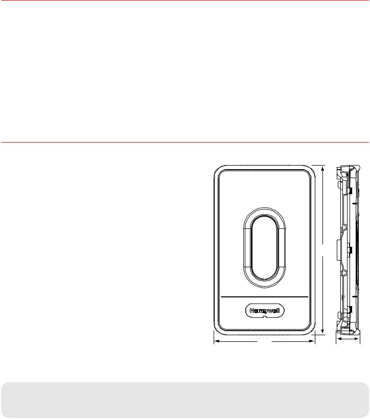
13.42
(341)
8 (203)
1.86 (47)
M24797
Fig. 1. HZ432 TrueZONE panel dimensions in in. (mm).
Need Help?
For assistance with this product please visit http://yourhome.honeywell.com or call Honeywell Zoning Hotline toll-free at 1-800-828-8367
Read and save these instructions.
® U.S. Registered Trademark. Patents pending. Copyright © 2008 Honeywell International Inc. All rights reserved.

HZ432 TrueZONE
Table 1. Recommended Thermostats.
System |
Non- |
Programmable |
|
Programmable |
|
|
|
|
Single- |
TH5110D, TH3110D, |
TH8110U, TH6110D, |
Stage |
T87N |
TH4110D |
|
|
|
Multi- |
TH5220D |
TH8320U, TH8321U, |
Stage |
|
TH6220D, YTH9421C |
|
|
|
Heat- |
TH5220D (2H/1C |
TH8320U (Up to 3H/2C) |
Pump |
only) |
TH8321U (Up to 3H/2C) |
|
TH3210D (2H/1C |
TH6320U* (Up to 3H/2C) |
|
only) |
TH6220D (2H/1C only) |
|
TH5320U* (Up to |
TH4210D (2H/1C only) |
|
3H/2C) |
YTH9421C |
|
|
|
Wire- |
TH5320R |
TH6320R |
less |
|
|
|
|
|
Note: All versions of the model numbers listed above will work with the applications they're listed for.
*This thermostat cannot control two stages of fossil fuel when in emergency heat mode.
Table 2. Recommended Dampers.
Type |
Honeywell |
Round |
Rectangular |
|
Damper |
|
|
|
|
|
|
Zone |
Spring-open/ |
ARD |
ZD |
|
power-closed |
|
|
|
|
|
|
Zone |
Power-open/ |
MARD/ |
For recommended |
|
power-closed |
RRD |
dampers call the |
|
|
|
Honeywell Zoning |
|
|
|
Hotline at |
|
|
|
1-800-828-8367. |
|
|
|
|
Bypass |
Static pres- |
SPRD |
SPRD |
|
sure regulat- |
|
|
|
ing damper |
|
|
|
|
|
|
Accessories
Table 3. Maximum Dampers.*
Ambient Temp. |
Maximum Damper VA per Zone |
|
|
100°F (38°C) |
28.8 |
|
|
160°F (71°C) |
16.8 |
|
|
*Use an SDCR (Slave Damper Control Relay) for additional dampers.
Maximum dampers per panel is limited by transformer size.
Ensure transformer is large enough to power the panel (10 VA) and dampers.
Table 4. Accessories.
Accessory |
Description |
|
|
40 VA transformer* |
AT140A1042* |
|
|
75 VA transformer |
AT175A1008 |
|
|
Discharge Air Temperature |
DATS C7735A1000* |
Sensor * |
|
|
|
Wired Outdoor Air |
C7089U1006 (hard wired) |
Temperature Sensor |
|
|
|
Wireless Outdoor Air |
C7089R1013 (wireless) |
Temperature Sensor |
|
|
|
Wireless Adapter |
THM4000R1000 |
|
|
TAZ-4 |
TotalZone® Add-A-ZoneTM |
|
Control Panel |
|
|
SDCR |
Slave Damper Control |
|
Relay |
|
|
Wireless Remote Control |
REM5000R1001 |
|
|
* Included in HZ432K kit. |
|
|
69-2198—01 |
Installation Guide
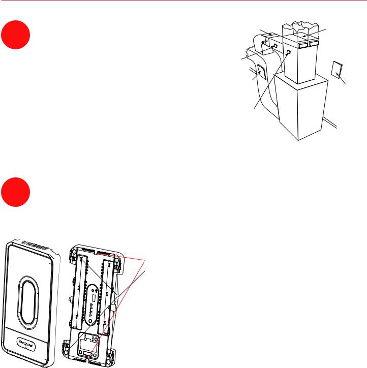
Mounting
Mount the HZ432 TrueZONE panel near the HVAC
1equipment; locate it on a wall, stud, roof truss, or coldair return.
NOTE: The HZ432 TrueZONE panel can be mounted in any orientation; level it for appearance only.
Please refer to TrueZONE Panel Frequently Asked Questions form 50-9694 for operating details.
SPRD BYPASS |
ZD SERIES |
|
DAMPER |
ZONE DAMPERS |
|
DATS |
SUPPLY |
|
DUCT |
||
(ALTERNATE |
||
LOCATION) |
|
|
TrueZONE PANEL |
|
|
MOUNTED ON |
TrueZONE PANEL |
|
RETURN DUCT |
||
MOUNTED ON WALL |
||
|
||
DATS |
|
|
(AT LEAST 3 FT |
|
|
FROM PLENUM) |
|
FURNACE OR |
|
AIR CONDITIONER |
M24738 |
Fig. 2
2Separate the zone panel cover from the base, and use the base as a template to drill mounting holes. Attach the base to the wall, stud, roof truss, or duct with appropriate screws (not included).
Use two screws for attaching to a stud or roof truss, or four screws for duct or drywall/plaster installations.
M24807
Fig. 3
69-2198—01
HZ432 TrueZONE
Wiring
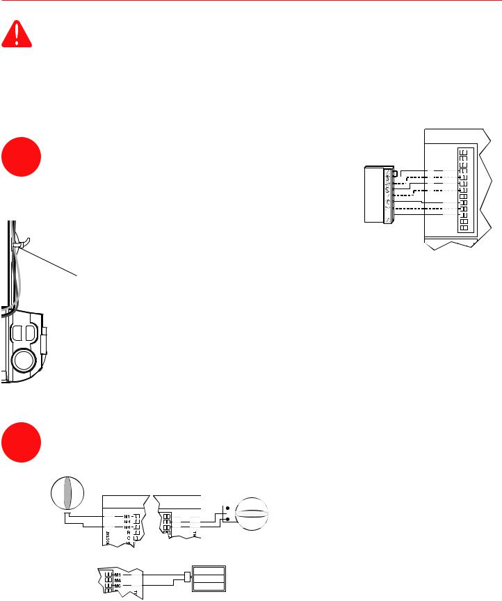
CAUTION: Voltage Hazard.
Can cause electrical shock or equipment damage. Disconnect power before beginning installation. Wire entire panel before applying transformer power.
Follow these steps for wiring all systems. However, wiring will vary depending on equipment. For conventional systems, refer to this page. For heat pump systems, see pages 6 and 7. For dual fuel systems, see pages 8 and 9.
Wiring must comply with applicable codes, ordinances, and regulations. Use the following wiring diagrams to wire the zone panel to the thermostats and dampers.
Install thermostats using instructions provided with thermostats.
3Connect thermostat to zone panel. To connect wire to the panel, strip approximately 1/4 in. of insulation and push wire into terminal. To release wire, press the button on top of the terminal.
THERMOSTAT
G 
M24808
Fig. 4
The HZ432 offers many innovations for wire management and organization: wires can be run behind the panel, through wire channels on its sides, and must be attached to a wiring anchor with a cable tie.
M24743 |
|
Fig. 5 |
|
4 |
Install dampers using instructions provided with dampers. |
Connect dampers to zone panel. |
NOTE: Multiple dampers can be wired in parallel.
ARD OR ZD DAMPER SPRING-OPEN POWER-CLOSED
DAMPER
M1 COMMON  M4 OPEN
M6 CLOSED
RRD OR MARD DAMPER POWER-OPEN POWER-CLOSED
ARD OR ZD DAMPER SPRING-OPEN POWER-CLOSED
Fig. 6
M24920
|
69-2198—01 |
 Loading...