


HE360
Table of contents
 Loading...
OWNER’S MANUAL
69-2631ES-05
HE360 Humidifier and
Installation Kit

HE360 HUMIDIFIER AND INSTALLATION KIT
69-2631ES—05 2
WELCOME
To the comfortable world of humidified air. When you use your Honeywell humidifier, notice that your skin is not
as dry, and that your scratchy throat and irritated nasal passages that aggravate allergies and asthma are
steadily improving.
You have also taken the first step in reducing the zapping you create when you walk on your carpet and then
touch your TV, computer, metal door knob or your pet. Your furniture and woodwork are also benefitting from the
difference that humidified air makes.
Congratulations! You have just made a great investment in improving the comfort of your home.
APPLICATION
This kit contains your new Honeywell HE360 Humidifier, H8908 Humidistat and all the accessories required for
installation.
INSTALLATION
Preparing for the Installation
Be sure to identify all the included accessories (Table 1) and make sure the appropriate tools are available
before beginning the installation.
Required Tools
Tools required for installation include:
• Tin snip.
•Screwdriver.
• Adjustable or open-end wrench.
• Drill, punch or awl.
• Level.
•Pliers.
•Nut driver.
• Wire stripper.
• 3/4 in. drill bit.
HE360 HUMIDIFIER AND INSTALLATION KIT
3 69-2631ES—05
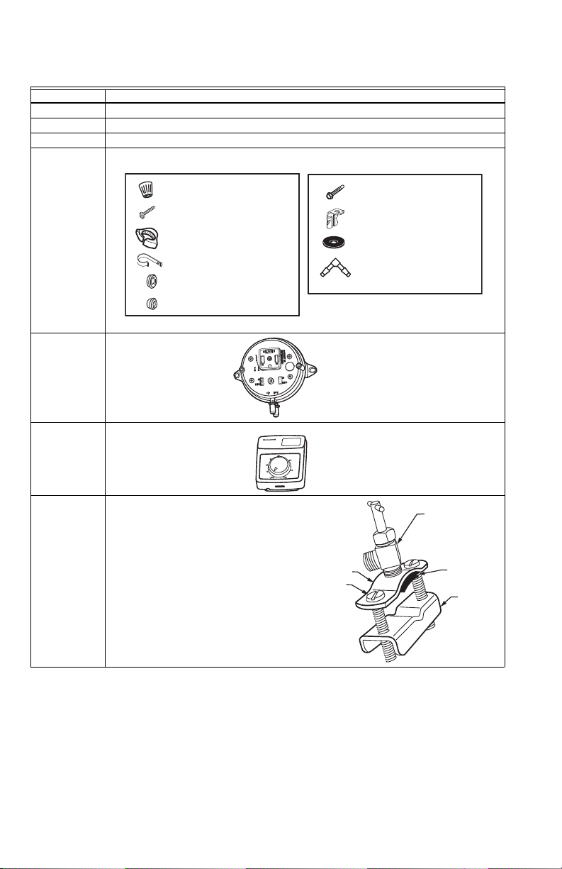
Included Accessories
Table 1. ncluded Accessories.
Quantity Accessory
20 ft (6.2m) 18 gauge, two-strand thermostat wire
20 ft (6.2m) 1/4 in. (6.35 mm) OD feed water tubing
10 ft (3.1m) 1/2 in (12.7 mm) ID drain tubing
2 bags Connecting and mounting hardware:
1Pressure switch
1 H8908 Humidistat
1 bag
Saddle Valve Assembly:
Saddle valve and top clamp (1)
Threaded bottom clamp (1)
Bolts (2)
Rubber gasket (1)
Eyelet (1)
Plastic bushing (1)
M34594
#8 SHEET METAL SCREW (18)
SELF-TAPPING SCREWS (2)
BAG #1
BAG #2
WIRE NUT (5)
DRAIN TUBE CLAMP (1)
FEED TUBE MOUNTING CLAMP (6)
BRASS INSERT (2)
PLASTIC COMPRESSION RING (2)
SPADE CONNECTOR (2)
TUBING ELBOW (2)
BLACK RUBBER GASKET (2)
M34599
Humidity Control
Régulateur d'humidité
-20 ¡F
-10 ¡F
0 ¡F
+10 ¡F
+20 ¡F
O
ver 20 ¡F
15%
20%
25%
30%
35%
40%
HUMIDITY
SETTING
OUTDOOR
TEMPERATURE
-30 ¡C
-25 ¡C
-20 ¡C
-10 ¡C
-5 ¡C
Over 0 ¡C
M31000A
SADDLE VALVE
ASSEMBLY
SADDLE VALVE
BOLTS
BOTTOM
CLAMP
RUBBER
GASKET
TOP CLAMP
HE360 HUMIDIFIER AND INSTALLATION KIT
69-2631ES—05 4
Determining Best Location for Humidifier
CAUTION
Temperature and Static Pressure Hazard.
Can cause property or equipment damage.
Locate humidifier where ambient temperature is between 32°F (0°C) and 160°F (71°C).
Do not install humidifier where freezing temperatures could occur.
Be sure supply plenum static pressure is no greater than 0.4 in. wc and water pressure is no greater than
124 psi.
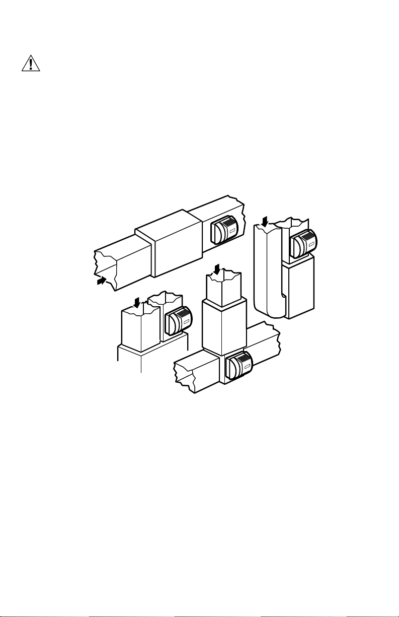
• Select a location for the humidifier on the supply (warm air stream) plenum. See Fig. 1.
• Select a location that cannot damage the air conditioner A-coil during installation.
• Do not locate the humidifier on the furnace body.
• Allow adequate clearance in front of and above the humidifier so you can easily remove the cover to perform
routine maintenance.
— Mount the humidifier at least 3 in. (78 mm) above the furnace body to allow adequate space for the sole-
noid valve and drain line.
— Mount the humidifier in a conditioned space to prevent freezing.
Fig. 1. Typical humidifier installation locations.
Selecting Water Supply Location
• Use either hard or soft water in the humidifier and either hot or cold water. The water flow rate, with the
humidifier running, is 3.5 gal/hr (13 liters/hr) to flush the pad and provide moisture for evaporation.
• Mak e sure t hat the 20 ft (6 .2m) of feed wat er tubi ng provided is adequate to connect the water supply (saddle
valve) with the humidifier solenoid valve.
M12808A
HORIZONTAL
DOWN
FLO
LOWBOY
RETURN
RETURN
RETURN
HIGHBOY
RETURN
HE360 HUMIDIFIER AND INSTALLATION KIT
5 69-2631ES—05
Locating Closest Floor Drain
• Select location with access to a floor drain to provide drainage for air conditioner condensation and
humidifier drainage.
• If you do not have a drain available, we recommend that you install the Honeywell Whole House Drum or Disk
Humidifier. Make sure that the 10 ft (3.1m) of drain tubing is adequate to reach from the humidifier drain
connection to the floor drain.
Selecting Location for Humidistat
• Select a location for the humidistat on the return plenum or on the wall in the living space.
— Mounting on the return plenum is the easiest installation for the control wiring circuit.
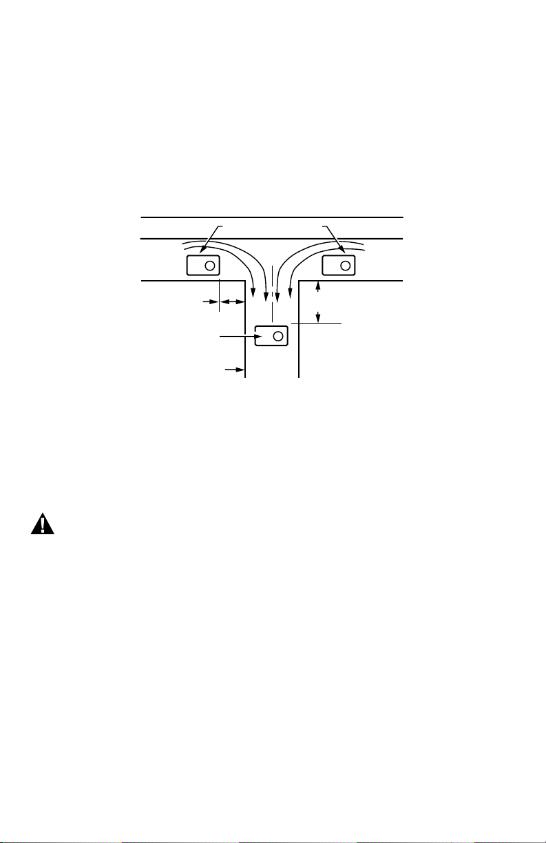
For return duct mounting, the humidistat should be mounted upstream from the humidifier or bypass so that it
is properly sensing the relative humidity of the living space. Locate the control at least 8 in. (203 mm) upstream
from the humidifier in the return air duct. (See Fig 2.)
Fig. 2. Selecting duct location for humidistat.
Locating Closest 120V Electrical Outlet
• Select location with access to an outlet. If not available, contact an electrician to have one installed.
• Make sure that the humidifier cord is adequate to reach from the humidifier to the outlet.
• Make sure that the 20 ft (6.2 m) of thermostat wire is adequate to reach from the humidifier solenoid, to the
pressure switch, to the humidistat.
Installing the Humidifier
WARNING
Hazardous Voltage
Can cause personal injury or equipment damage.
Do not cut or drill into any air conditioning or electrical accessory.
ALTERNATE LOCATION
RETURN
AIR
RETURN
AIR
6 in. (152 mm)
MINIMUM
15 in. (381 mm)
MINIMUM
BEST
LOCATION
RETURN AIR DUCT
M12831
HE360 HUMIDIFIER AND INSTALLATION KIT
69-2631ES—05 6
CAUTION
Sharp Edges Installation Hazard.
Can cause personal injury.
Wear gloves and safety glasses.
1. Turn off power to the air handing system at the circuit breaker.
2. Draw a level line on the plenum in the location
chosen for the humidifier. (Leveling assures optimal humidifier performance.)
3. Locate the template (form number 69-2641 included in the box).
4. Tape the template in position and trace around the template.
5. Remove the template and carefully cut the rectangular opening.
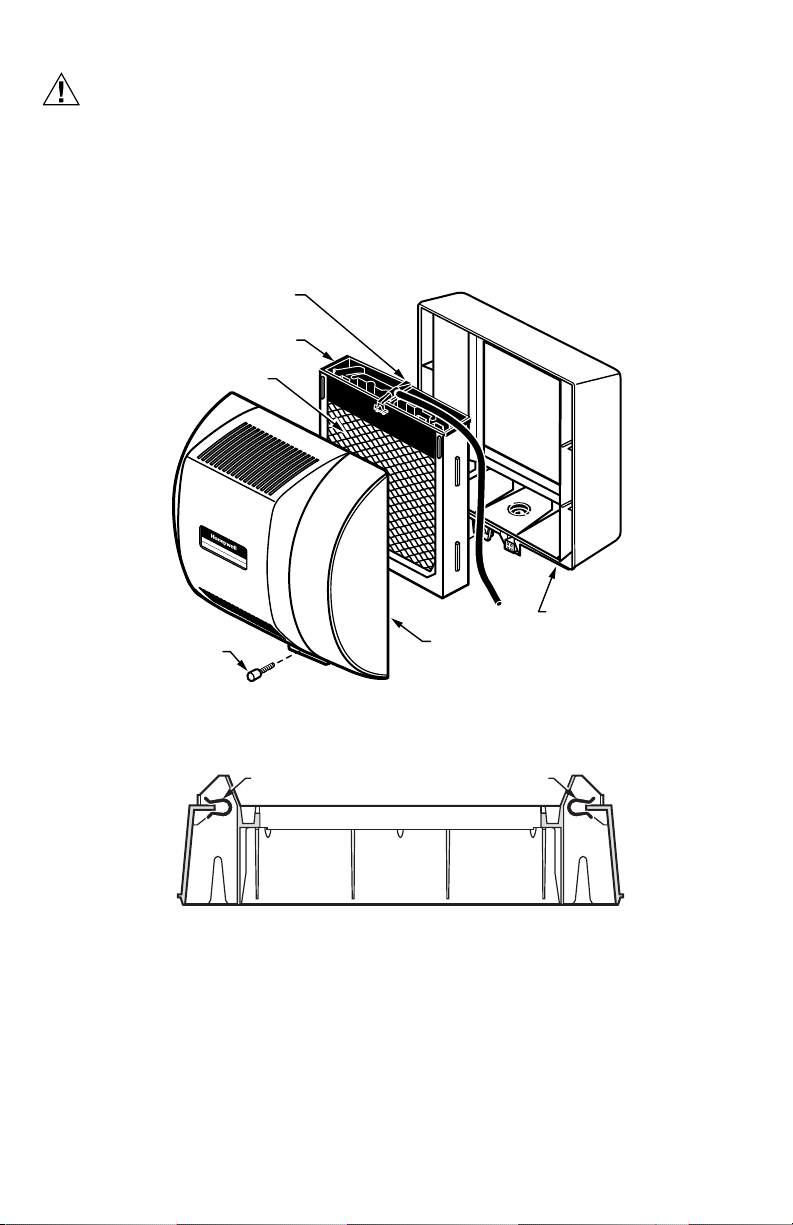
6. Disassemble the humidifier; remove the cover and take out the humidifier pad assembly. See Fig. 3.
Fig. 3. Disassembling humidifier.
7. Position the securing clips as shown in Fig. 4.
Fig. 4. Position securing clips.
M12809
COVER
ASSEMBLY
HUMIDIFIER
PAD ASSEMBLY
FEED TUBE NOZZLE
WATER
DISTRIBUTION TRAY
HUMIDIFIER
HOUSING
THUMB
SCREW
M12813B
CLIP
CLIP
TOP VIEW – HUMIDIFIER HOUSING

HE360 HUMIDIFIER AND INSTALLATION KIT
7 69-2631ES—05
8. Make sure th e humidifier housing i s level, th en position it in the opening so the plastic tabs are in place on
the upper sheet metal edge of the opening.
Use pliers, as necessary, to flatten cut edges. See Fig. 5.
9. Push in securing clips until completely seated.
10. Drill holes and install the three sheet metal screws on the top of the humidifier housing. Secure the hous-
ing with the three remaining screws.
Fig. 5. Installing humidifier on duct.
11. Reinstall the humidifier pad assembly in the humidifier housing.
IMPORTANT
Be sure to reconnect the water feed tube and ensure that the tube is not pinched or kinked.
12. Hinge the cover in place and secure with the thumbscrew located at the bottom of the cover.
DUCT
LEVEL
SHEET METAL
SCREWS (4)
PLASTIC
TABS (2)
DRAIN TUBING
M20204C
OPENING
TO AIR DUCT
HE360 HUMIDIFIER AND INSTALLATION KIT
69-2631ES—05 8
Connecting the Plumbing
Use hot or cold water and either hard or softened water in the humidifier.
1. Shut off the water.
CAUTION
Chemical Hazard.
Can cause personal injury or equipment damage.
Do not use any line connected to an air conditioner.
Do not use gas line.
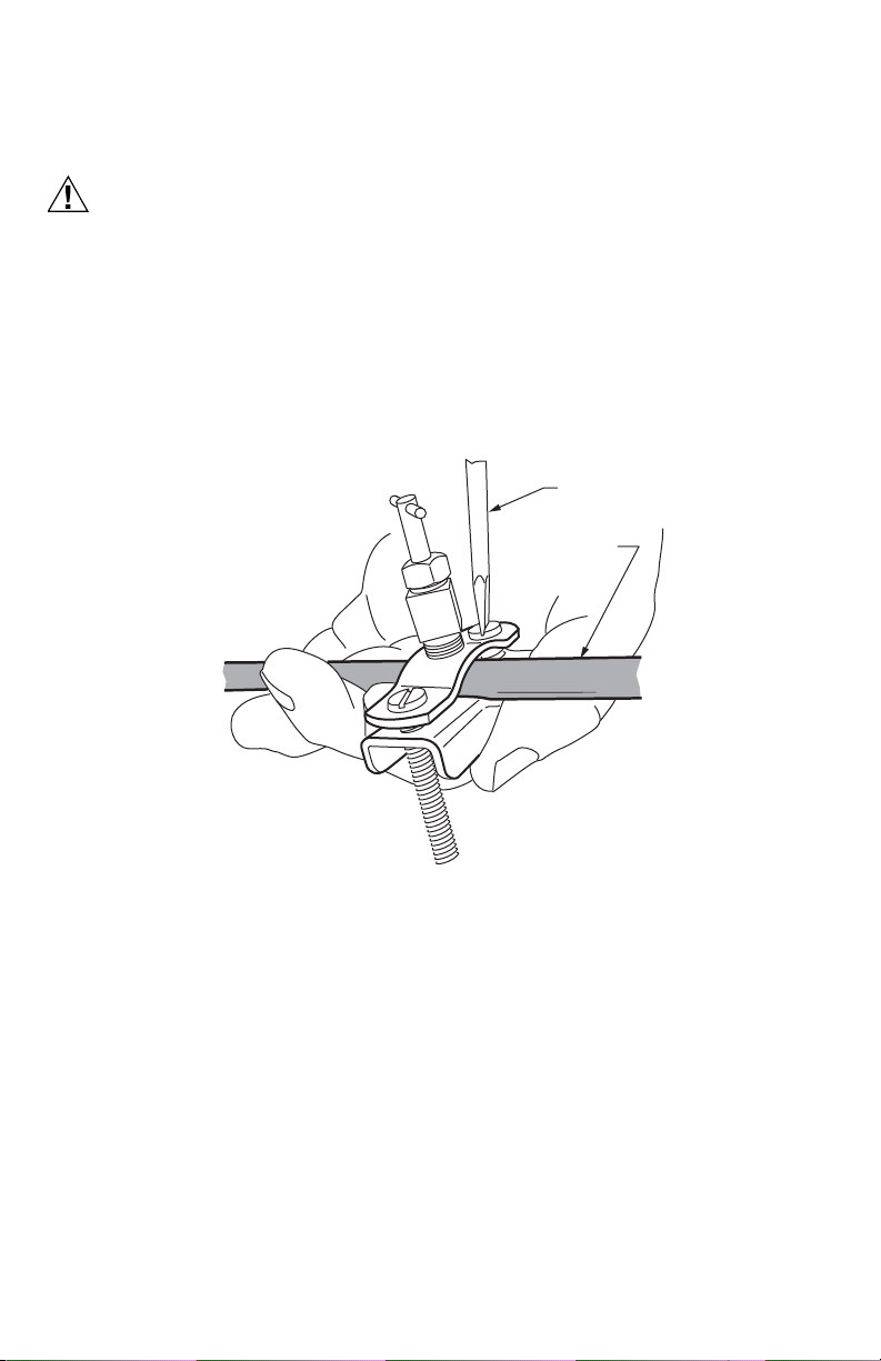
2. Use the self-piercing saddle valve (included) to tap into the water supply line at the location selected. See
Fig. 6. If tapping into galvanized pipe, drain line and pre-drill 3/16 in. tap for saddle valve.
NOTE: The saddle valve is not designed to regulate water flow. The valve is either open or closed.
IMPORTANT
To prevent debris from clogging the solenoid in-line filter, be sure to install the saddle valve handle point-
ing toward the ceiling.
Fig. 6. Installing the saddle valve.
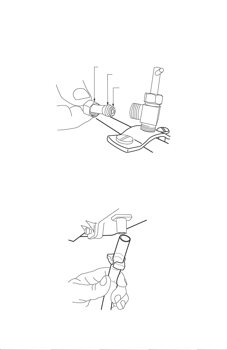
3. Use 1/4 in. (6 mm) OD tubing and connect the saddle valve to the inlet side of the solenoid valve on the
humidifier (see Fig. 7).
a. Place the brass compression nut over the tubing.
b. Install brass insert into end of tubing.
c. Slide the plastic compression ring over the tubing. (Discard copper compression ring provided with
valve.)
M20175
SCREW DRIVER
WATER LINE
HE360 HUMIDIFIER AND INSTALLATION KIT
9 69-2631ES—05
NOTE: To prevent leaking, use plastic (Delrin) sleeve rings with plastic tubing. Use copper sleeve rings
only with copper tubing.
d. Insert the tubing into the solenoid valve fitting and support the valve while tightening the compression
nut.
NOTE: Do not over-tighten the compression nut. Moderate tightness prevents leaking.
e. Repeat steps a. through d. for solenoid valve fitting.
f. Secure tubing with clamps provided.
Fig. 7. Installing feed tubing.
4. Connect a 1/2 in. (13 mm) drain tube to the humidifier drain fitting and run to the floor drain (see Fig. 8).
a. Slide the drain clamp over the tubing.
b. Push the tubing over the drain nipple on the humidifier.
c. Tighten the clamp around the tubing using a pliers/hand to secure the humidifier drain.
d. Fasten the drain tubing (can use duct tape) along the route to prevent movement and ensure down-
ward slope for correct drainage.
NOTE: Cut tubing to correct length so the tubing terminates at the drain.
Fig. 8. Installing the drain tubing.
M20176
BRASS COMPRESSION NUT
PLASTIC
COMPRESSION RING
BRASS INSERT
M20177
HE360 HUMIDIFIER AND INSTALLATION KIT
69-2631ES—05 10
Installing the Pressure Switch
IMPORTANT
Do not install the switch in an area where temperature exceeds rating of
-40°F to 190°F (-40°C to 88°C).
1. Disconnect power from the humidifier before
installing.
2. Mount the switch vertically with pressure
connectors facing down, using provided self-
tapping screws to secure the switch to the duct.
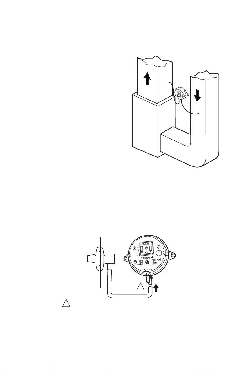
3. Cut 3/4-in. diameter holes in the supply and
return ducts within 10 feet of the switch to
ensure the provided tubing reaches the pressure
tap elbows. See Fig. 9.
4. Insert the black rubber gaskets into the duct
holes.
5. Connect the tubing to the tubing fitting elbows
and insert the tubing fitting elbows into the
black rubber gaskets in each duct.
6. Connect the other end of the tubing to the
applicable pressure connection on the switch.
a. Connect supply duct tubing to the +
connection.
b. Connect return duct tubing to the –
connection
7. You may cut the tubing to fit the connection
length between the elbow fitting and switch. It is
also recommended to secure the hose to
existing structures to avoid accidental
disconnection.
Fig. 9. Mounting the pressure switch.
Fig. 10. Install tubing.
M27303
A
B
SUPPLY DUCT INSTALL - AIR LINE ONLY TO TAP A,
CONNECTED TO THE + PORT ON THE AIR FLOW SWITCH
RETURN DUCT INSTALL - AIR LINE ONLY TO TAP B,
CONNECTED TO THE – PORT ON THE AIR FLOW SWITCH
SUPPLY/RETURN DUCT INSTALL - AIR LINE CONNECTED
TO BOTH THE + AND – PORTS ON THE AIR FLOW SWITCH
M27304
INSIDE
OF DUCT
CONNECT TUBING TO + CONNECTION IF PRESSURE TAP IS
MOUNTED TO SUPPLY DUCT. CONNECT TO – IF PRESSURE
TAP IS MOUNTED TO RETURN DUCT.
1
1

HE360 HUMIDIFIER AND INSTALLATION KIT
11 69-2631ES—05
Installing the Humidistat
Installing on Mounting Duct
1. Apply the template to the duct location chosen for the humidistat. Make sure the template is level before
drilling the holes.
2. Refer to the template (provided with the H8908 Humidistat Installation Instructions) to drill the control
assembly opening and mounting holes for the H8908.
3. Remove the H8908 case from the base.
4. Position the foam gasket on the H8908 base.
5. Position the base on the duct with the arrow up.
6. Secure the base to the duct using the four
1 in. (25 mm) mounting screws provided with humidistat.
NOTE: For wall mounting instructions, see the H8908 Installation Instructions.
Fig. 11. Humidistat base and rear view.
M20179
WIRE SLOT
HUMIDIST AT WIRES
HUMIDISTAT BASE REAR OF HUMIDISTAT
HE360 HUMIDIFIER AND INSTALLATION KIT
69-2631ES—05 12
WIRING
CAUTION
Hazardous Voltage.
Can cause personal injury or equipment damage.
Disconnect power supply before installing or servicing equipment.
IMPORTANT
— Use THIS wiring diagram—NOT the one supplied with humidistat instructions.
— All wiring must comply with applicable local code, ordinances and regulations.
Wire the humidifier solenoid valve, pressure switch and humidistat. See Fig. 12.
NOTE: It is acceptable to switch the position of the red and white wires when wiring the equipment.
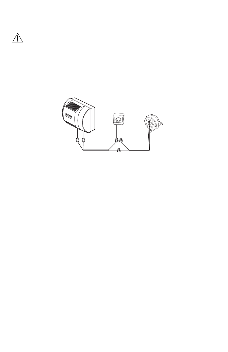
Fig. 12. Wiring the controls.
1. Run the two-strand thermostat wire from the humidifier to the humidistat, and from the humidistat to the
pressure switch.
2. Cut two (2) lengths of thermostat wire to reach between components, leaving adequate wire at both ends
for connections.
NOTE: Humidistat and pressure switch can be wired in any order.
3. At the humidifier, use one length of thermostat wire to connect a red wire to one of the yellow humidifier
wires and a white wire to the remaining yellow humidifier wire. (The red wires from the humidifier are not
used.)
4. At the pressure switch, use the remaining length of thermostat wire to connect a red wire to the C terminal
and a white wire to the NO terminal using spade connectors and pliers. (The NC terminal is not used.)
5. Connect the white wires from each length of thermostat wire to each of the black wires of the humidistat
using wire nuts.
6. Connect the remaining red wires together using a wire nut.
M34590
H
u
m
i
d
i
ty
C
o
n
t
r
o
l
R
é
g
u
la
t
e
u
r
d
'
h
u
m
i
d
i
t
é
-
2
0
¡
F
-
1
0
¡
F
0
¡
F
+
1
0
¡F
+
2
0
¡
F
O
v
e
r
2
0
¡F
1
5
%
2
0
%
2
5
%
3
0
%
3
5
%
4
0
%
H
U
M
I
D
IT
Y
S
E
T
T
I
N
G
O
U
T
D
O
O
R
TE
M
P
E
R
A
T
U
R
E
-
3
0
¡
C
-
25
¡
C
-
2
0
¡
C
-
1
0
¡
C
-
5
¡
C
Ov
e
r
0
¡
C
HUMIDISTAT
AIR PRESSURE
SWITCH
YELLOW
YELLOW
RED
WHITE
BLACK
BLACK
RED
WHITE
WHITE
HUMIDIFIER
RED
WHITE
RED
Loading...