


HPF24S6
Honeywell HPF24S6, HPF24S8, HPF24S6E, HPF24S8E, HPF24S6C User Manual
...
INSTALLATION MANUAL
HPF24S6 & HPF24S8, HPF24S6E &
HPF24S8E, HPF24S6C & HPF24S8C
FIELD CHARGER/POWER SUPPLY
P/N 52751:E1 • ECN 11-237 • 4/14/2011

2 HPF24S Series Power Supplies — P/N 52751:E1 4/14/2011
Fire Alarm System Limitations
While a fire alarm system may lower insurance rates, it is not a substitute for fire insurance!
An automatic fire alarm system—typically made up of
smoke detectors, heat detectors, manual pull stations, audible
warning devices, and a fire alarm control panel with remote
notification capability—can provide early warning of a develop-
ing fire. Such a system, however, does not assure protection
against property damage or loss of life resulting from a fire.
The Manufacturer recommends that smoke and/or heat detec-
tors be located throughout a protected premise following the
recommendations of the National Fire Protection Association
Standard 72 (NFPA 72), manufacturer's recommendations,
State and local codes, and the recommendations contained in
the Guides for Proper Use of System Smoke Detectors, which
are made available at no charge to all installing dealers.
These documents can be found at http://www.systemsen-
sor.com/html/applicat.html. A study by the Federal Emer-
gency Management Agency (an agency of the United States
government) indicated that smoke detectors may not go off in
as many as 35% of all fires. While fire alarm systems are
designed to provide early warning against fire, they do not
guarantee warning or protection against fire. A fire alarm sys-
tem may not provide timely or adequate warning, or simply
may not function, for a variety of reasons:
Smoke detectors may not sense fire where smoke cannot
reach the detectors such as in chimneys, in or behind walls, on
roofs, or on the other side of closed doors. Smoke detectors
also may not sense a fire on another level or floor of a building.
A second-floor detector, for example, may not sense a first-
floor or basement fire.
Particles of combustion or “smoke” from a developing fire
may not reach the sensing chambers of smoke detectors
because:
• Barriers such as closed or partially closed doors, walls, or
chimneys may inhibit particle or smoke flow.
• Smoke particles may become “cold,” stratify, and not reach
the ceiling or upper walls where detectors are located.
• Smoke particles may be blown away from detectors by air
outlets.
• Smoke particles may be drawn into air returns before
reaching the detector.
The amount of “smoke” present may be insufficient to alarm
smoke detectors. Smoke detectors are designed to alarm at
various levels of smoke density. If such density levels are not
created by a developing fire at the location of detectors, the
detectors will not go into alarm.
Smoke detectors, even when working properly, have sensing
limitations. Detectors that have photoelectronic sensing
chambers tend to detect smoldering fires better than flaming
fires, which have little visible smoke. Detectors that have ion-
izing-type sensing chambers tend to detect fast-flaming fires
better than smoldering fires. Because fires develop in different
ways and are often unpredictable in their growth, neither type
of detector is necessarily best and a given type of detector
may not provide adequate warning of a fire.
Smoke detectors cannot be expected to provide adequate
warning of fires caused by arson, children playing with
matches (especially in bedrooms), smoking in bed, and violent
explosions (caused by escaping gas, improper storage of
flammable materials, etc.).
Heat detectors do not sense particles of combustion and
alarm only when heat on their sensors increases at a predeter-
mined rate or reaches a predetermined level. Rate-of-rise
heat detectors may be subject to reduced sensitivity over time.
For this reason, the rate-of-rise feature of each detector
should be tested at least once per year by a qualified fire pro-
tection specialist. Heat detectors are designed to protect
property, not life.
IMPORTANT! Smoke detectors must be installed in the
same room as the control panel and in rooms used by the sys-
tem for the connection of alarm transmission wiring, communi-
cations, signaling, and/or power. If detectors are not so
located, a developing fire may damage the alarm system, crip-
pling its ability to report a fire.
Audible warning devices such as bells may not alert people
if these devices are located on the other side of closed or
partly open doors or are located on another floor of a building.
Any warning device may fail to alert people with a disability or
those who have recently consumed drugs, alcohol or medica-
tion. Please note that:
• Strobes can, under certain circumstances, cause seizures
in people with conditions such as epilepsy.
• Studies have shown that certain people, even when they
hear a fire alarm signal, do not respond or comprehend the
meaning of the signal. It is the property owner's responsi-
bility to conduct fire drills and other training exercise to
make people aware of fire alarm signals and instruct them
on the proper reaction to alarm signals.
• In rare instances, the sounding of a warning device can
cause temporary or permanent hearing loss.
A fire alarm system will not operate without any electrical
power. If AC power fails, the system will operate from standby
batteries only for a specified time and only if the batteries have
been properly maintained and replaced regularly.
Equipment used in the system may not be technically com-
patible with the control panel. It is essential to use only equip-
ment listed for service with your control panel.
Telephone lines needed to transmit alarm signals from a
premise to a central monitoring station may be out of service
or temporarily disabled. For added protection against tele-
phone line failure, backup radio transmission systems are rec-
ommended.
The most common cause of fire alarm malfunction is inade-
quate maintenance. To keep the entire fire alarm system in
excellent working order, ongoing maintenance is required per
the manufacturer's recommendations, and UL and NFPA stan-
dards. At a minimum, the requirements of NFPA 72 shall be
followed. Environments with large amounts of dust, dirt or
high air velocity require more frequent maintenance. A main-
tenance agreement should be arranged through the local man-
ufacturer's representative. Maintenance should be scheduled
monthly or as required by National and/or local fire codes and
should be performed by authorized professional fire alarm
installers only. Adequate written records of all inspections
should be kept.
Limit-C1-2-2007

HPF24S Series Power Supplies — P/N 52751:E1 4/14/2011 3
Installation Precautions
Adherence to the following will aid in problem-free installation with long-term reliability:
WARNING - Several different sources of power can be
connected to the fire alarm control panel. Disconnect all
sources of power before servicing. Control unit and associ-
ated equipment may be damaged by removing and/or insert-
ing cards, modules, or interconnecting cables while the unit is
energized. Do not attempt to install, service, or operate this
unit until manuals are read and understood.
CAUTION - System Re-acceptance Test after Software
Changes: To ensure proper system operation, this product
must be tested in accordance with NFPA 72 after any pro-
gramming operation or change in site-specific software. Re-
acceptance testing is required after any change, addition or
deletion of system components, or after any modification,
repair or adjustment to system hardware or wiring. All compo-
nents, circuits, system operations, or software functions known
to be affected by a change must be 100% tested. In addition,
to ensure that other operations are not inadvertently affected,
at least 10% of initiating devices that are not directly affected
by the change, up to a maximum of 50 devices, must also be
tested and proper system operation verified.
This system meets NFPA requirements for operation at 0-49º
C/32-120º F and at a relative humidity 93% ± 2% RH (non-
condensing) at 32°C ± 2°C (90°F ± 3°F). However, the useful
life of the system's standby batteries and the electronic com-
ponents may be adversely affected by extreme temperature
ranges and humidity. Therefore, it is recommended that this
system and its peripherals be installed in an environment with
a normal room temperature of 15-27º C/60-80º F.
Verify that wire sizes are adequate for all initiating and indi-
cating device loops. Most devices cannot tolerate more than a
10% I.R. drop from the specified device voltage.
Like all solid state electronic devices, this system may
operate erratically or can be damaged when subjected to light-
ning induced transients. Although no system is completely
immune from lightning transients and interference, proper
grounding will reduce susceptibility. Overhead or outside aerial
wiring is not recommended, due to an increased susceptibility
to nearby lightning strikes. Consult with the Technical Ser-
vices Department if any problems are anticipated or encoun-
tered.
Disconnect AC power and batteries prior to removing or
inserting circuit boards. Failure to do so can damage circuits.
Remove all electronic assemblies prior to any drilling, filing,
reaming, or punching of the enclosure. When possible, make
all cable entries from the sides or rear. Before making modifi-
cations, verify that they will not interfere with battery, trans-
former, or printed circuit board location.
Do not tighten screw terminals more than 9 in-lbs. Over-
tightening may damage threads, resulting in reduced terminal
contact pressure and difficulty with screw terminal removal.
This system contains static-sensitive components.
Always ground yourself with a proper wrist strap before han-
dling any circuits so that static charges are removed from the
body. Use static suppressive packaging to protect electronic
assemblies removed from the unit.
Follow the instructions in the installation, operating, and pro-
gramming manuals. These instructions must be followed to
avoid damage to the control panel and associated equipment.
FACP operation and reliability depend upon proper installation.
Precau-D1-9-2005
FCC Warning
WARNING: This equipment generates, uses, and can
radiate radio frequency energy and if not installed and
used in accordance with the instruction manual may
cause interference to radio communications. It has been
tested and found to comply with the limits for class A
computing devices pursuant to Subpart B of Part 15 of
FCC Rules, which is designed to provide reasonable
protection against such interference when devices are
operated in a commercial environment. Operation of this
equipment in a residential area is likely to cause interfer-
ence, in which case the user will be required to correct
the interference at his or her own expense.
Canadian Requirements
This digital apparatus does not exceed the Class A limits
for radiation noise emissions from digital apparatus set
out in the Radio Interference Regulations of the Cana-
dian Department of Communications.
Le present appareil numerique n'emet pas de bruits
radioelectriques depassant les limites applicables aux
appareils numeriques de la classe A prescrites dans le
Reglement sur le brouillage radioelectrique edicte par le
ministere des Communications du Canada.
HARSH™, NIS™, and NOTI•FIRE•NET™ are all trademarks; and Acclimate® Plus™, FlashScan®, NION®, NOTIFIER®, ONYX®, ONYXWorks®,
UniNet®, VeriFire®, and VIEW® are all registered trademarks of Honeywell International Inc. Echelon® is a registered trademark and LonWorks™ is a
trademark of Echelon Corporation. ARCNET® is a registered trademark of Datapoint Corporation. Microsoft® and Windows® are registered trademarks of
the Microsoft Corporation.
©2011 by Honeywell International Inc. All rights reserved. Unauthorized use of this document is strictly prohibited.

4 HPF24S Series Power Supplies — P/N 52751:E1 4/14/2011
Software Downloads
In order to supply the latest features and functionality in fire alarm and life safety technology to our customers, we make
frequent upgrades to the embedded software in our products. To ensure that you are installing and programming the latest
features, we strongly recommend that you download the most current version of software for each product prior to
commissioning any system. Contact Technical Support with any questions about software and the appropriate version for
a specific application.
Documentation Feedback
Your feedback helps us keep our documentation up-to-date and accurate. If you have any comments or suggestions about
our online Help or printed manuals, you can email us.
Please include the following information:
•Product name and version number (if applicable)
•Printed manual or online Help
•Topic Title (for online Help)
•Page number (for printed manual)
•Brief description of content you think should be improved or corrected
•Your suggestion for how to correct/improve documentation
Send email messages to:
FireSystems.TechPubs@honeywell.com
Please note this email address is for documentation feedback only. If you have any technical issues, please contact
Technical Services.

HPF24S Series Power Supplies — P/N 52751:E1 4/14/2011 5
Table of Contents
Section 1: System Overview....................................................................................................8
1.1: General...........................................................................................................................................................8
1.2: Features..........................................................................................................................................................8
1.3: Start-up Procedure .........................................................................................................................................9
1.4: Jumpers ..........................................................................................................................................................9
1.4.1: Jumper JP1 - Ground Fault Detection .................................................................................................9
1.4.2: Jumpers JP2 and JP3: Coded/Noncoded Input Selection ..................................................................10
1.5: LED Indicators.............................................................................................................................................10
1.6: Specifications...............................................................................................................................................10
1.7: General.........................................................................................................................................................13
Section 2: Installation.............................................................................................................14
2.1: Backbox Mounting ......................................................................................................................................14
2.2: NAC Circuit Wiring.....................................................................................................................................16
2.2.1: Style Y (Class B) ...............................................................................................................................16
2.2.2: ZNAC-4 Class A Option Module......................................................................................................16
2.3: Addressable Module Mounting ...................................................................................................................17
2.4: NEC Power-limited Wiring Requirements ..................................................................................................18
Section 3: Programming Options.......................................................................................... 19
3.1: DIP Switch Settings.....................................................................................................................................20
3.2: Programmable Features Description............................................................................................................21
3.2.1: Synchronization Type Selection........................................................................................................21
Maximum Number of Strobes for Synchronization .............................................................................21
3.2.2: Synchronization Mode - Master/Slave ..............................................................................................21
3.2.3: AC Fail Delay/Aux. Trouble Relay Function....................................................................................22
3.2.4: Input/Output Function .......................................................................................................................22
Auxiliary Power Control ......................................................................................................................23
3.2.5: Charger Enable/Disable.....................................................................................................................23
3.2.6: Door Closers......................................................................................................................................23
Section 4: Trouble Supervision............................................................................................. 25
4.1: Supervision via FACP Notification Appliance Circuit................................................................................25
4.1.1: Supervision of FACP to HPF24S wiring...........................................................................................25
4.1.2: Supervision of HPF24S Faults ..........................................................................................................25
4.1.3: Aux. Trouble Relay/AC Fail Relay ...................................................................................................25
4.2: AC Loss Reporting Delay............................................................................................................................26
Section 5: Applications .......................................................................................................... 27
5.1: Controlling Four NACs With One Input and Selective Silence ..................................................................27
5.2: Controlling Three NACs and One Door Holder With One Input................................................................29
5.3: Split Temporal Mode of Operation..............................................................................................................31
5.4: Remote Supply With Resettable and Nonresettable Power.........................................................................33
5.5: Master FACP with Slave HPF24S Power Supply .......................................................................................35
5.6: Master HPF24S Power Supply Connected to FACP ...................................................................................36
5.7: Canadian Applications.................................................................................................................................36
Section 6: Power Supply Requirements............................................................................... 38
6.1: Overview......................................................................................................................................................38
6.2: Calculating the AC Branch Circuit..............................................................................................................38
6.3: Calculating the System Current Draw .........................................................................................................39
6.3.1: Overview ...........................................................................................................................................39
6.3.2: How to Calculate System Current Draw ...........................................................................................39
6.4: Calculating the Battery Size ........................................................................................................................41
6.4.1: NFPA Battery Requirements .............................................................................................................41
6.4.2: Selecting and Locating Batteries .......................................................................................................41

Table of Contents
6 HPF24S Series Power Supplies — P/N 52751:E1 4/14/2011
Appendix A: Wire Requirements........................................................................................... 43
Index ........................................................................................................................................ 44

HPF24S Series Power Supplies — P/N 52751:E1 4/14/2011 7
It is imperative that the installer understand the requirements of the Authority Having Jurisdiction
(AHJ) and be familiar with the standards set forth by the following regulatory agencies:
• Underwriters Laboratories Standards
• NFPA 72 National Fire Alarm Code
NFPA Standards
NFPA 72 National Fire Alarm Code
NFPA 70 National Electrical Code
Underwriters Laboratories Documents:
UL 464 Audible Signaling Appliances
UL 864 Standard for Control Units for Fire Protective Signaling Systems
UL 1638 Visual Signaling Appliances
UL 1971 Signaling Devices for Hearing Impaired
CAN/ULC - S524-01 Standard for Installation of Fire Alarm Systems
CAN/ULC-S527-99 Standard for Control Units for Fire Alarm Systems
Other:
NEC Article 250 Grounding
NEC Article 300 Wiring Methods
NEC Article 760 Fire Protective Signaling Systems
Applicable Local and State Building Codes
Requirements of the Local Authority Having Jurisdiction (LAHJ)
Canadian Electrical Code, Part 1
Other HPP Documents:
Device Compatibility Document Document #54399
This product has been certified to comply with the requirements in the Standard for Control Units
and Accessories for Fire Alarm Systems, UL 864, 9th Edition. Operation of this product with prod-
ucts not tested for UL 864, 9th Edition has not been evaluated. Such operation requires the
approval of the local Authority Having Jurisdiction (AHJ).
Before proceeding, the installer should be familiar with the following documents.

8 HPF24S Series Power Supplies — P/N 52751:E1 4/14/2011
Section 1: System Overview
The HPF24S6 is a 6 amp power supply and the HPF24S8 is an 8 amp power supply. Each HPF24S
power supply is a compact, cost-effective, remote power supply and battery charger which provides
ADA compatible strobe synchronization. Each remote power supply consists of a filtered 24 VDC
output that can be configured to drive four Style Y (Class B) NACs (Notification Appliance Cir-
cuits). The four circuits can be configured for Style Z (Class A) with the optional ZNAC-4 Class A
converter module. Alternatively, the four output circuits may be configured as 24 VDC resettable
or nonresettable power outputs. The input circuits, which control the power supply operation, are
triggered by the reverse polarity of an NAC or by a 12 VDC or 24 VDC power source. The power
supplies are compatible with 12 VDC and 24 VDC control panels.
The HPF24S6E and HPF24S8E offer the same features as the HPF24S6 and HPF24S8 respectively
but allow connection to 220/240 VAC. Unless otherwise specified, the information in this manual
applies to both the 110/120 VAC versions and the 220/240 VAC versions of the power supplies.
The HPF24S6C and HPF24S8C are the Canadian versions which offer the same features as the
HPF24S6 and HPF24S8 respectively. Unless otherwise specified, the information in this manual
also applies to the Canadian versions of the power supplies.
1.1 General
The HPF24S power supplies can be used as remotely mounted power supplies and battery chargers
to power four noncoded or coded NACs. The Main FACP (Fire Alarm Control Panel) NAC(s) is
connected to the remote power supply input circuit(s). When the control input circuit activates due
to reverse polarity of the NAC from the FACP, the power supply will activate its Notification
Appliance Circuits.
During the inactive or nonalarm state, the power supply supervises its NAC field wiring for short
and open conditions. AC fail, battery, charger and ground fault troubles will also be monitored by
the power supply. If an NAC or power supply fault is detected, the power supply Normally-Closed
Trouble contact will open.
If an alarm condition occurs and the NAC is activated, the supervision is disabled and the Notifica-
tion Appliance Circuit is no longer supervised (except for shorts). Supervision of other power sup-
ply faults such as low battery, AC loss, ground fault and battery charger trouble will continue and
may be monitored via the Trouble relay contacts.
1.2 Features
• Self-contained in a lockable cabinet
• 24 VDC remote power supply
• Outputs are completely power-limited
• Two optically-isolated input/control circuits, compatible with 12 VDC and 24 VDC control
panel NACs
• Four output circuits:
– Fully filtered power
– Four 24 VDC Style Y (Class B) NACs (special application)
– Optional ZNAC-4 Class A converter module for conversion to Style Z NACs
– Alternatively, all four circuits may be configured as 24 VDC special application power
outputs
– Output circuits may be configured as resettable or nonresettable
• NAC Trouble LED - blinks to indicate the number of the circuit in trouble
• Maximum current available for any one output circuit: 3.0 amps
• Maximum total continuous current available:

HPF24S Series Power Supplies — P/N 52751:E1 4/14/2011 9
Start-up Procedure System Overview
– 4.0 amps for HPF24S6
– 6.0 amps for HPF24S8
• Maximum total short term current (one hour maximum):
– 6.0 amps for HPF24S6
– 8.0 amps for HPF24S8
• Integral supervised battery charger for lead acid batteries only
• Capable of charging 7.0 AH to 18.0 AH (Amp Hour) batteries
• Fully supervised power supply, battery and NACs
• Selectable Strobe Synchronization for NACs (System Sensor, Gentex and Wheelock)
• Coded signal synchronization
• Fixed terminal blocks for field wiring capable of accepting 12 - 22 AWG wire
• Selectable Ground Fault detection by jumper JP1
• Power supply trouble Form-C relay contacts (fail-safe)
• Optional delay of AC loss reporting for 2 hours
• Auxiliary Special Application Power Output for SLC modules (500 mA maximum) with
optional reset for 4-wire smoke detectors
• Mounting location for optional addressable control module
1.3 Start-up Procedure
1. Configure the power supply jumpers as described in “Jumpers” on page 9.
2. Install the power supply as described in“Installation” on page 14.
3. Program the power supply as described in “Programming Options” on page 19.
4. Wire the power supply circuits, referring to the options described in“Trouble Supervision” on
page 25 and the application examples in“Applications” on page 27.
5. Connect primary power source wiring while observing the following:
– Make certain that the AC mains circuit breaker is off before making any wiring connections
between the mains and the power supply.
– Make certain primary power source is 120 VAC, 60 Hz, 3.2 amps.
– Run a pair of wires (with ground conductor) from the protected premises main breaker box
to TB1 of the power supply main circuit board.
– Use 14 AWG (1.6 mm O.D.) or heavier gauge wire with 600V insulation.
6. Apply power to the power supply using the following procedure:
– Apply AC power by turning on the AC mains circuit breaker connected to the power supply.
– Connect a properly charged battery to connector JP4 on the power supply main circuit
board.
1.4 Jumpers
1.4.1 Jumper JP1 - Ground Fault Detection
The Ground Detection circuit monitors for zero impedance between the power supply and ground.
Jumper JP1 is located in the top right section of the power supply circuit board. Cutting JP1 will
disable ground fault detection by the power supply. This should only be done if ground faults are
being monitored by a panel connected to the HPF24S power supply.
!
CAUTION: DISCONNECT POWER
REMOVE ALL POWER (AC & DC) BEFORE CUTTING OR MOVING ANY JUMPERS.

10 HPF24S Series Power Supplies — P/N 52751:E1 4/14/2011
System Overview LED Indicators
1.4.2 Jumpers JP2 and JP3: Coded/Noncoded Input Selection
Jumpers JP2 and JP3 are located in the top right section of the power
supply circuit board. JP2 is used for Control Input Circuit #1 and
JP3 is used for Control Input Circuit #2. The position of these jump-
ers will depend on the type of signal being fed to the input circuits:
• If the source voltage to the input circuit is a noncoded (steady
voltage) input signal, the jumper for the corresponding input
circuit should be in the default position which jumpers the
bottom two pins (as illustrated in drawing at left).
• If the source voltage to the input circuit is coded (variable
voltage), the jumper for the corresponding input circuit should
be moved to jumper the top two pins.
1.5 LED Indicators
• AC Power on (green) LED - indicates AC power is present
• Ground Fault (yellow) LED - indicates a ground fault condition (zero impedance to ground)
• Battery Trouble (yellow) LED - indicates low or no battery
• NAC Trouble (yellow) LED - indicates a Notification Appliance Circuit trouble (blinks once
for Circuit 1 trouble, twice for Circuit 2 trouble, three times for Circuit 3 trouble and four times
for Circuit 4 trouble. Note that multiple circuits in trouble will cause the LED to blink the
number of the circuit with the highest number)
• ChargerTrouble/AC Loss (yellow) LED - indicates a charger fault or loss of AC power:
– If AC is applied to the power supply without a battery connected, both the Charger
Trouble/AC Loss LED and Battery Trouble LED will turn on simultaneously, indicating that
a battery is not connected.
– When a battery is connected and the power supply is in Normal Mode, if the battery voltage
drops too low or the battery is disconnected, only the Battery Trouble LED will turn on.
– When a battery is connected and the charger develops a problem, only the Charger
Trouble/AC Loss LED will turn on.
1.6 Specifications
Refer to Figure 1.1 on page 12 for terminal locations.
Primary AC Power - TB1
• HPF24S6(C) & HPF24S8(C): 120 VAC, 60 Hz, 3.2 amps maximum
• HPF24S6E & HPF24S8E: 240 VAC, 50 Hz, 1.6 amps maximum
• Wire size: minimum #14 AWG with 600V insulation
Control Input Circuits - TB4, Terminals 3 (+) & 4 (-) and 7 (+) & 8 (-)
• Trigger Input Voltage: 9 to 32 VDC
• Input Current Draw in Alarm Polarity:
– 16 to 32 volts, 2.0 mA maximum per input
– 9 to 16 volts, 1.0 mA maximum per input
NAC/Output Circuits - TB2, Terminals 1 (+) & 2 (-), 3 (+) & 4 (-), 5 (+) & 6 (-) and
7 (+) & 8 (-) alarm polarity
• Supervised, Special Application and power-limited
• Voltage Rating: 24 VDC filtered
• Current:
Jumper positions shown
for noncoded (steady)
source voltage
JP3
JP2
jumpers
24s8jp3b.wmf

HPF24S Series Power Supplies — P/N 52751:E1 4/14/2011 11
Specifications System Overview
– Maximum for any one circuit - 3.0 amps
– Maximum total continuous
current for all output:
HPF24S6 - 4.0 amps
HPF24S8 - 6.0 amps
– Maximum total short term
current (one hour maximum) for all outputs:
HPF24S6 - 6.0 amps
HPF24S8 - 8.0 amps
• Output Circuit Types:
– Four Style Y NACs (require 4.7 KEnd-of-Line Resistors) or
Style Z NACs using the optional ZNAC-4 Class A converter module
OR
– Four resettable or nonresettable 24 VDC power outputs
• Refer to the HPP Device Compatibility Document #54399 for listed compatible devices.
• For wiring requirements, refer to “Wire Requirements” on page 43.
Trouble Relay Contact Rating - TB5
• Fail-safe Form-C relay (normally energized, transfers with loss of power)
• 5.0 amps @ 24 VDC or 5.0 amps @ 30 VAC
Secondary Power (battery) Charging Circuit - JP4
• Supervised, nonpower-limited
• Supports lead acid type batteries only
• Float Charge Voltage: 27.6 VDC
• Maximum Charge Current: 1.5 A
• Battery fuse (F1) 15A, 32V (Canadian version is nonreplaceable 12A, 32V)
• Maximum Battery Capacity: 18.0 AH
• Minimum Battery Capacity: 7.0 AH
• Power supply draws maximum standby current of 65 mA from batteries
Auxiliary Special Application Power Output - TB4 Terminals 9 (+) & 10 (-)
• Special application power
• Power-limited, nonsupervised
• Voltage Rating: 24 VDC
• Current:
– 170 mA maximum with internal 7.0 Amp Hour batteries
12 HPF24S Series Power Supplies — P/N 52751:E1 4/14/2011
System Overview Specifications
– 500 mA maximum with external 18.0 Amp Hour batteries
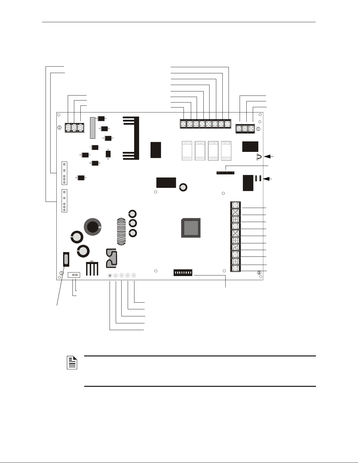
1 2 3 4 5 6 7 8
ON
TB1
J2
TRANSFORMER 2
TRANSFORMER 1
J1
F1
JP4
SW1
TB4
JP3
J3
TB5
TB2
JP1
JP2
- +
EARTH NEUT HOT
OUT4
- NAC4 +
OUT3
- NAC3 +
OUT2
- NAC2 +
OUT1
- NAC1 +
8 7 6 5 4 3 2 1
3 2 1
10
9
8
7
6
5
4
3
2
1
AUX -
IN2-
IN2+
OUT1-
OUT1+
IN1-
IN1+
SYNC IN -
SYNC IN +
AUX +
NO NC
AUX TBL
COM
BATTERY
AC
BATT
AC/
CHGR
GND
FLT
NAC
TRBL
Figure 1.1 HPF24S Board Layout
- Aux. Common
+ Aux. 24 VDC*
- Control Input 2
+ Control Input 2
- Out Common
+ Out/Trouble Contact
- Control Input 1
+ Control Input 1
- Sync Input
+ Sync Input
NAC/Out 1 +
NAC/Out 1 -
NAC/Out 2 +
NAC/Out 2 -
NAC/Out 3 +
NAC/Out 3 -
NAC/Out 4 +
NAC/Out 4 -
Supervised,
Nonpower-limited
Earth
AC Neutral
AC Hot
Trouble Relay
Form-C Fail-safe
Nonsupervised
(shown energized)
Normally Open
Normally Closed
Common
JP1 Ground Fault
Detection
(cut to disable)
see Note at
bottom of the
page.
JP2 & JP3
Coded/Noncoded
Input Selection
JP4 Supervised
+ Battery
- Battery
18 AH, 24 VDC
Nonpower-
limited
LEDs
Charger Trouble/AC Loss (yellow)
NAC Trouble (yellow)
Battery Trouble (yellow)
Ground Fault (yellow)
AC Power (green)
SW1
Programming
DIP Switches
(change switch
settings only
when all power
(AC & DC) is
removed)
F1
Battery Fuse
15A, 32V
(Canadian version
is nonreplaceable
12 A, 32V)
Nonpower-limited
To Transformer #1
To Transformer #2
Auxiliary Output
500 mA Special
Application Power*
J3
ZNAC-4 Connector
*Note: Auxiliary Power
Output is power-limited
but not supervised
Power-limited, Supervised,
Special Application
in NAC Mode
24fs8brd.wmf
NOTE: Cutting Ground Fault jumper JP1 voids UL/NFPA Style/Class identifications for circuits
unless Ground Faults are being monitored by an FACP connected to the power supply. Cut
jumper JP1 only if a panel connected to the power supply is monitoring for Ground Faults or with
the approval of AHJ (Authority Having Jurisdiction).
HPF24S Series Power Supplies — P/N 52751:E1 4/14/2011 13
General System Overview
1.7 General
The HPF24S may be used in a number of different applications. It may be used as a remotely-
mounted power supply and battery charger where it can provide up to four coded or noncoded, syn-
chronized or nonsynchronized NACs (Notification Appliance Circuits). Alternatively, output #4
can be used as a door holder circuit which will provide a steady 24 VDC output until an alarm con-
dition or AC fail condition causes it to drop to 0 VDC following a 10 second delay. All four out-
puts can also provide power.
One possible application for the HPF24S remote power supply utilizes the NAC repeater feature.
In this application, one or two NACs are connected from the main FACP to the remote power sup-
ply control input circuits. When the control input circuits are activated by the reverse polarity of
the NACs, the power supply will activate its corresponding output circuits as programmed by SW1
DIP switch configuration (refer to Table 3.1 on page 20).
During the inactive state, the remote power supply supervises its NAC field wiring for short and
open conditions. If a fault is detected, the power supply will enter a trouble condition and illumi-
nate the NAC Trouble LED. When the NACs are activated, the supervision is disabled and the cir-
cuits are no longer supervised (except for short circuit conditions). Supervision of other power
supply faults such as low battery, battery charger trouble, ground fault and AC loss will continue
and may be monitored via the power supply trouble relay.
If an application requires that all four outputs activate at the same time, only one NAC is required
from the FACP. For this application, the NAC is connected to control input circuit #1 and SW1
DIP switch is set for this operation.
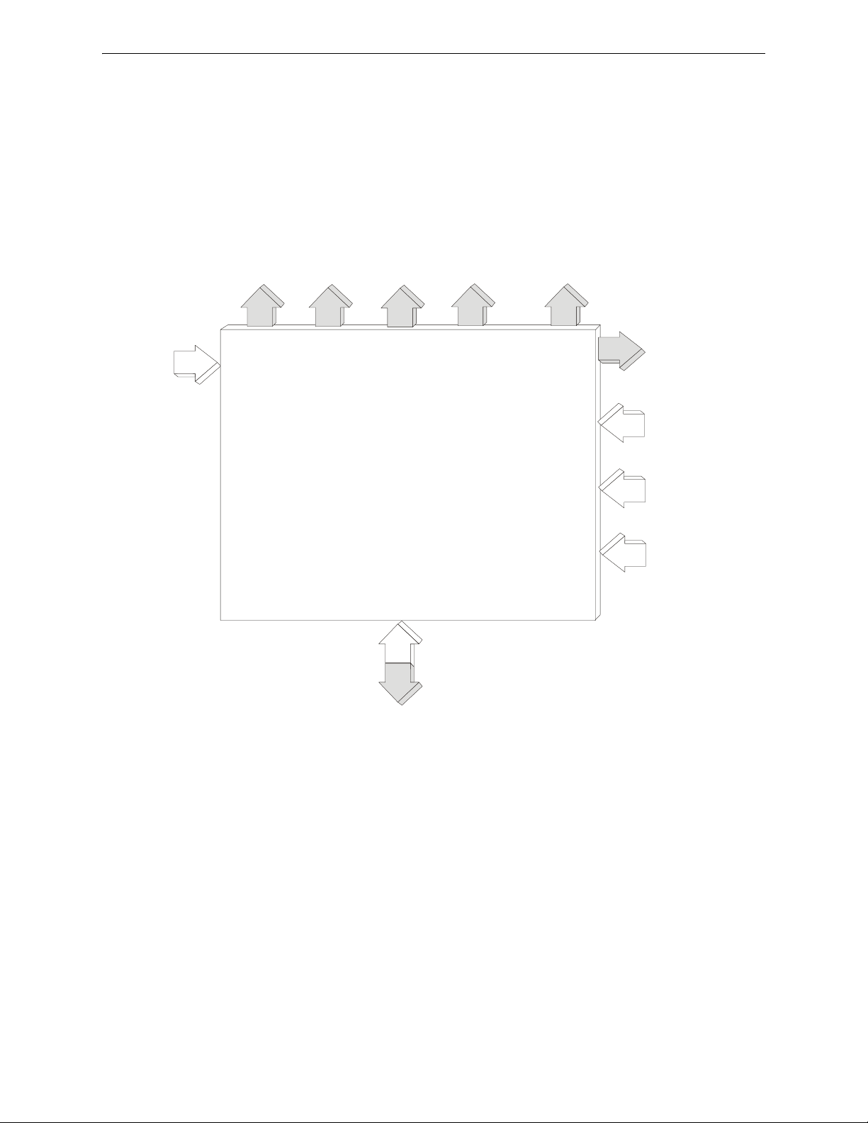
Style Y NAC
or Door
Holder Power
Output #4
AC Power
Figure 1.2 Simplified HPF24S Block Diagram
Battery Charger
Style Y NAC
Output #3
Style Y NAC
Output #2
Style Y NAC
Output #1
Note: All NAC
outputs can be
converted to Style Z
with a ZNAC-4
option module
FCPS Trouble
Contact Output
24 VDC Specific
Application Power
NAC Control
Input #2
(from FACP)
NAC Control
Input #1
(from FACP)
Sync. Input
Input/Output Functions are Programmable
by SW1 DIP Switch Settings
24fsblok.wmf
14 HPF24S Series Power Supplies — P/N 52751:E1 4/14/2011
Section 2: Installation
Carefully unpack the system and check for shipping damage. Select a location for the cabinet that
is in a clean, dry, vibration-free area where extreme temperatures are not encountered. The area
should be readily accessible with sufficient room to easily install and maintain the power supply.
Locate the top of the cabinet approximately five feet above the floor with the hinge mounting on
the left. Determine the number of conductors required for the devices to be installed and determine
the appropriate knockouts. All wiring must be in accordance with the National and/or Local codes
for fire alarm systems and power supplies.
2.1 Backbox Mounting
1. Remove the PC board and transformers from the backbox before installing backbox. Set the
board and transformers aside in a safe, clean place. Avoid static discharge which may damage
static sensitive components on the board.
2. Mark and predrill holes for the top two keyhole mounting bolts.
3. Install two upper fasteners in the wall with the screw heads protruding approximately ¼”.
4. Using the upper keyholes, mount the backbox over the two screws.
5. Mark the lower two holes, remove the backbox from the wall and drill the mounting holes.
6. Mount the backbox, install the remaining fasteners and tighten all screws.
7. When the location is dry and free of construction dust, reinstall the PC board and transformers
and continue with the installation.
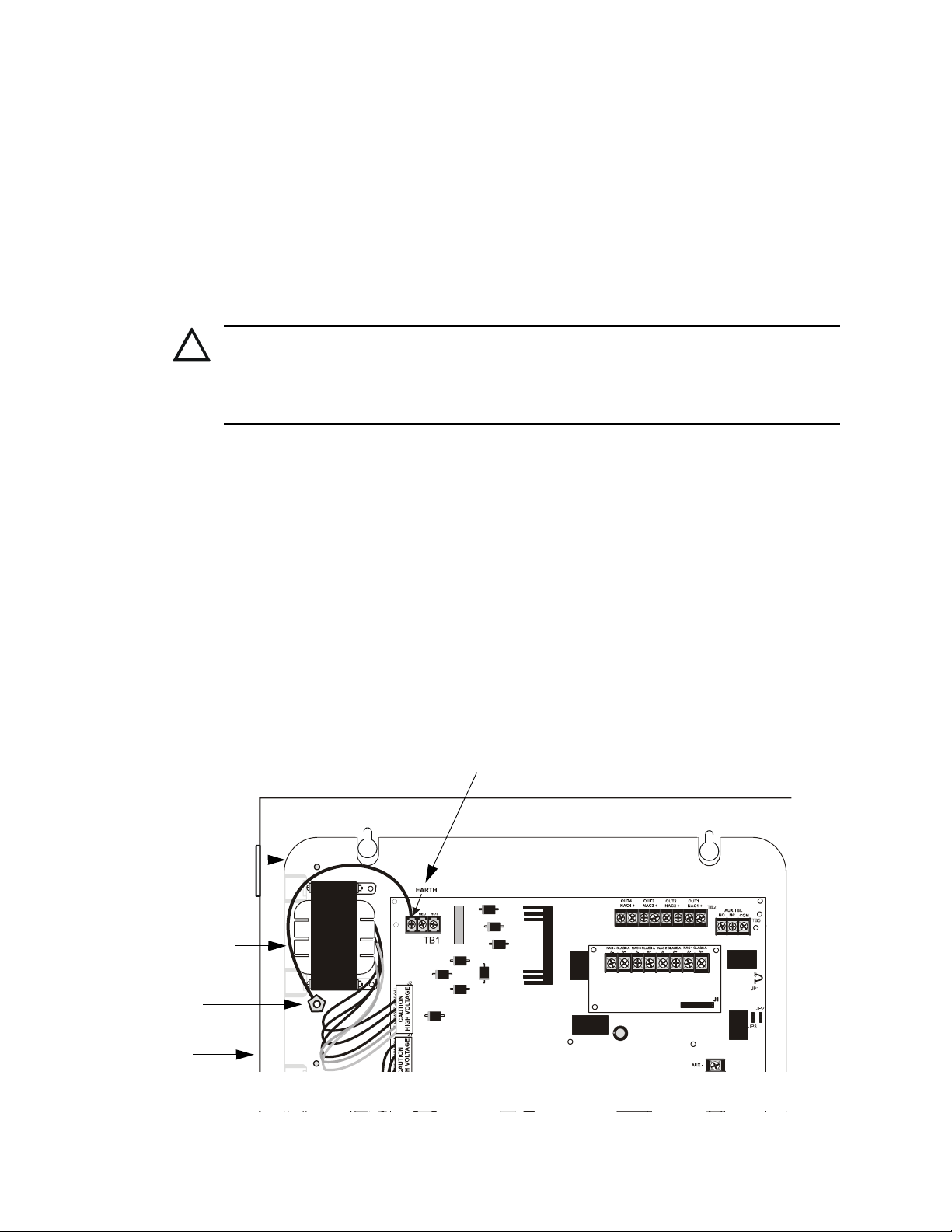
8. IMPORTANT! Make certain to connect the supplied grounding strap between the Earth
terminal on TB1 (AC Terminal Block) of the main circuit board and the chassis ground stud as
illustrated in Figure 2.1:
!
CAUTION: STATIC SENSITIVE COMPONENTS
THE CIRCUIT BOARD CONTAINS STATIC-SENSITIVE COMPONENTS. ALWAYS GROUND
YOURSELF WITH A PROPER WRIST STRAP BEFORE HANDLING ANY BOARDS SO THAT
STATIC CHARGES ARE REMOVED FROM THE BODY. USE STATIC SUPPRESSIVE PACKAGING
TO PROTECT ELECTRONIC ASSEMBLIES.
Ground Stud
Grounding Strap
Earth Terminal on TB1 (AC Terminal Block)
Backbox
Mounting Plate
24fsgrnd.wmf
Figure 2.1 Grounding Strap
HPF24S Series Power Supplies — P/N 52751:E1 4/14/2011 15
Backbox Mounting Installation
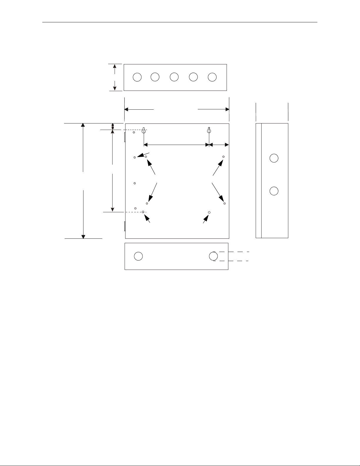
Figure 2.2 Backbox Mounting Dimensions
Bottom
Height=15.00”
(38.10 cm)
10.625”
(26.99 cm)
0.75”
(1.9 cm)
2.875” (7.3 cm)
Backbox = 14.5”
(36.8 cm)
Depth = 3.050”
(7.75 cm)
Top
9.1” (23.1 cm)
2.7”
(6.86cm)
1.125” (2.868 cm)
Mounting Plate Pem Studs
Backbox Mounting Holes
fcpscabb.wmf
Ground Stud
 Loading...