


Remote-adjustable
Radiator Controller
HR 10 F
Mounting and Operation

|
Content |
Content |
|
Overview |
3 |
Mounting |
5 |
Selecting the mounting site |
5 |
Mounting the drive unit |
5 |
Mounting the operating unit |
11 |
Connecting the operating unit and the drive unit |
11 |
Inserting batteries into the operating unit |
13 |
Setting the date and time |
14 |
Operation |
15 |
Display and operating elements at the operating unit |
15 |
Changing the setpoint temperature at the adjusting ring |
16 |
Changing the operating modes |
17 |
Automatic functions |
18 |
Emergency operation when the batteries are flat |
19 |
Disabling the Roomtronic (child-proofing) |
19 |
Adapting |
20 |
Adapting the comfort and economy temperatures |
21 |
Adapting the heating and economy periods |
22 |
Adaptation at the radiator valve |
25 |
Appendix |
27 |
Technical data |
27 |
Dimensions and drilling scheme operating unit |
28 |
1

Content
Adapters for the drive unit |
29 |
Help with problems |
30 |
Glossary |
32 |
2

Overview
Overview
For Your Information
Technical terms are explained in the glossary (Page 32). They are identified in the text by an *.
Application
The Roomtronic HR10 F controls the setpoint temperature* of a room. It consists of a drive unit and an operating unit and offers a number of comfortable functions:
•A separate time program can be entered for each weekday.
•The manual adjusting ring at the operating unit allows simple changing of the room temperature at any time – also in automatic mode*.
The manual adjusting ring of the drive unit does not have any function.
•Self-monitoring properties offer protection against calcification, unintentional setpoint adjustment and frost.
•A flashing display 
 draws the user's attention to the fact that the batteries have to be changed.
•The Roomtronic changes automatically between summer and winter times.
•Various valve adapters and a window contact are furthermore available.
3

Overview
Scope of supply
1.Operating unit
2.Connecting cable
3.Drive unit
4. Valve lantern
5. Batteries
1 2
3 |
4 |
5 |
4
Mounting
Mounting
Selecting the mounting site
►When selecting the mounting site take into consideration that the temperature measurement is influenced if the operating unit is mounted on an outer wall or near heat sources.
Mounting the drive unit
►Turn the radiator on before mounting. The radiator valve must be open.
HINT: The correct setting of the valve is best checked with the central heating switched on. If the valve is correctly mounted, the radiator will become warm.
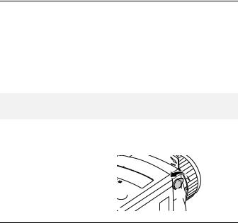
Separating the drive unit from the valve lantern
►Remove the old radiator controller, if necessary.
► To open the retainer bracket, turn the control knob (1) so the tip points upwards.


 À
À
5
Mounting
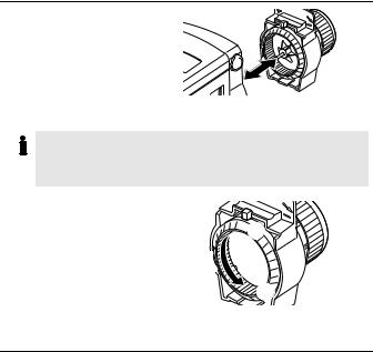
► Separate the drive unit and valve lantern.
Mounting the valve lantern on the radiator valve
The Honeywell-Braukmann, MNG, Heimeier, Junkers, Landis & Gyr 'Duogyr' valves do not require an adapter. For adapters for Oventrop-, Danfoss-, Herzand Vaillant valves please refer to Page 29.
►Turn the adjusting ring (3) of the valve lantern to the left, until the nose (1) of the adjusting ring is positioned at the stop (2) of the housing.

 À Á
À Á

Â
6

Mounting
► Slide the valve lantern onto the heating valve.
► Slide the metal knurled nut onto the thread of the heating valve.
►Tighten the metal knurled nut without using a tool.
7
Mounting
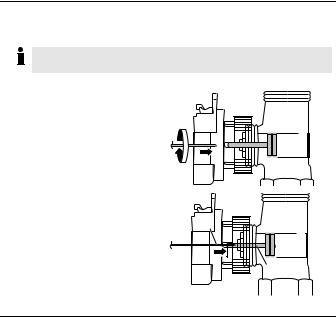
Checking the valve lift
The nose of the adjusting ring is positioned at the stop of the housing (Page 6).
►Turn the adjusting ring of the valve lantern (1) to the right until some resistance is felt.
The spindle (2) of the valve lantern is now touching the valve pin (3) of the radiator valve (4).
À
Á
 Ã
8
Mounting
►Turn the adjusting ring of the valve lantern (1) further to the right until the final stop is reached.
The radiator |
valve |
is |
|
||
closed. |
With |
the |
central |
|
|
heating |
switched |
on, |
the |
À |
|
radiator cools down. |
|
||||
The valve lift between the left-hand stop (open) and the righthand stop (closed) has to amount to at least ¾ of a rotation.
9
 Loading...