


 Loading...
UltraKey Lite
Keyboard controller for VideoBloX and MAXPRO-Net Matrix Systems
HJC5000
Installation and User Guide
Document 800-07422 – Rev A – 08/10
Installation and User
Guide

Revisions
Issue |
Date |
Revisions |
|
|
|
800-03854 rev A |
02/2009 |
New document. |
|
|
|
800-03854 rev B |
03/2009 |
Updated the MaxPRO map code. |
|
|
|
800-03854 rev C |
04/2009 |
Corrected the controller login PIN code; corrected IP address p. 59; |
|
|
updated images for quality |
|
|
|
800-07422 rev A |
08/2010 |
Revisions to Step 3: Configure Address, Baud Rate or IP for VideoBloX |
|
|
Mode; Step 4: Configure VideoBloX Mode Default Settings While Powering |
|
|
Up; Step 4: Configure the Controller for an Ethernet Connection; added |
|
|
Step 5: Setting the Keyboard Address While Powering Up; and, the System |
|
|
Configuration Menu screen. |
|
|
|
|
|
|
|
|
|
4
Explanation of Symbols
WARNING! The exclamation point in a red octagon is a WARNING. Failure to take or avoid a specific action could result in physical harm to a person or irreparable damage to equipment.
Caution The lightning flash with arrowhead symbol within an equilateral triangle alerts the user to the presence of uninsulated dangerous voltage within the enclosure of the product that may be of sufficient magnitude to constitute a risk of electric shock to the person
Caution The exclamation point in a yellow equilateral triangle is a Caution. Failure to take or avoid a specified action could result in loss of data or damage to equipment and may contain important operating and maintenance servicing information.
FCC Compliance Statement
Information to the User: This equipment has been tested and found to comply with the limits for a Class B digital device. Pursuant to Part 15 of the FCC Rules, these limits are designed to provide reasonable protection against harmful interference in a residential installation. This equipment generates, uses, and can radiate radio frequency energy and, if not installed and used in accordance with the instruction manual, may cause harmful interference to radio communications. However, there is no guarantee that interference will not occur in a particular installation.
If this equipment does cause harmful interference to radio or television reception, which can be determined by turning the equipment off and on, the user is encouraged to try to correct the interference. For example, try orienting or relocating the receiving antenna, increasing the separation between the equipment and receiver, or connecting the equipment to an outlet on a different circuit.
This device complies with part 15 of the FCC rules. Operation is subject to the following two conditions: (1) This device may not cause harmful interference, and (2) this device must accept any interference received, including interference that may cause undesired operation.
Document 800-07422 Rev A |
5 |
08/10 |
|
Changes or modifications not expressly approved by the party responsible for compliance could void the user’s authority to operate the equipment.
Users of the product are responsible for checking and complying with all federal, state and local laws and statutes concerning the monitoring and recording of video and audio signals. Honeywell Systems Group shall not be held responsible for the use of this product in violation of current laws and statutes.
Canadian Compliance Statement
This Class B digital apparatus complies with Canadian ICES-003.
Cet appareil numérique de la classe B est conforme à la norme NMB-003 du Canada.
European Compliance Statement
The manufacturer declares that the equipment supplied with this guide is compliant with the essential protection requirements of the EMC directive 2004/108/EC and the Low Voltage Directive LVD 2006/95/EC, conforming to the requirements of standards EN 55022 for emissions, EN 50130-4 for immunity, and EN 60065 for Electrical Equipment safety.
Caution Users of the product are responsible for checking and complying with all federal, state, and local laws and statutes concerning the monitoring and recording of video and audio signals. Honeywell shall not be held responsible for the use of this product in violation of current laws and statutes.
Warnings and Cautions
Read the following cautions and warnings prior to installation and use of this product.
Installation and servicing must be performed by qualified personnel in accordance with local codes and regulations.
6
Consider using a UPS source to ensure satisfactory performance.
Using replacement parts or accessories other than the original manufacturers may invalidate the warranty.
C A U T I O N
RISK OF ELECTRIC SHOCK
DO NOT OPEN
CAUTION: TO REDUCE THE RISK OF ELECTRIC SHOCK,
DO NOT REMOVE COVER (OR BACK).
NO USER-SERVICEABLE PARTS INSIDE.
REFER SERVICING TO QUALIFIED SERVICE PERSONNEL.
Important Safety Instructions
BEFORE OPERATING OR INSTALLING THE UNIT, READ AND FOLLOW ALL INSTRUCTIONS. AFTER INSTALLATION, retain the safety and operating instructions for future reference
1.HEED WARNINGS - Adhere to all warnings on the unit and in the operating instructions.
2.INSTALLATION
•Install in accordance with the manufacturer’s instructions.
•Installation and servicing should be performed only by qualified and experienced technicians to conform to all local codes and to maintain your warranty.
•Do not install the unit in an extremely hot or humid location, or in a place subject to dust or mechanical vibration. The unit is not designed to be waterproof. Exposure to rain or water may damage the unit.
3.POWER SOURCES - This product should be operated only from the type of power source indicated on the marking label. If you are not sure of the type of power supplied to your facility, consult your product dealer or local power company.
4.HEAT - Situate away from items that produce heat or are heat sources such as radiators, heat registers, stoves, or other products (including amplifiers).
5.WATER AND MOISTURE - Do not use this unit near water or in an unprotected outdoor installation, or any area classified as a wet location.
6.ATTACHMENTS - Do not use attachments not recommended by the product manufacturer as they may result in the risk of fire, electric shock, or injury to persons.
7.ACCESSORIES - Only use accessories specified by the manufacturer.
8.CLEANING - Do not use liquid cleaners or aerosol cleaners. Use a damp cloth for cleaning.
9.SERVICING - Do not attempt to service this unit yourself as opening or removing covers may expose you to dangerous voltage or other hazards. Refer all servicing to qualified service personnel.
Document 800-07422 Rev A |
7 |
08/10 |
|
10.REPLACEMENT PARTS - When replacement parts are required, be sure the service technician has used replacement parts specified by the manufacturer or have the same characteristics as the original part. Unauthorized substitutions may result in fire, electric shock or other hazards.
Warranty and Service
Subject to the terms and conditions listed on the Product Warranty Card, during the warranty period Honeywell will repair or replace, at its sole option, free of charge, any defective products returned prepaid.
In the event you have a problem with any Honeywell product, call Customer Service for assistance or to request a Return Merchandise Authorization (RMA) number. Be sure to have the model number, serial number, and the nature of the problem available for the technical service representative.
In the U.S.A. and Canada, call 1.800.796.2288. See the back cover for other contact details.
Prior authorization must be obtained for all returns, exchanges, or credits. Items shipped to Honeywell without a clearly identified Return Merchandise Authorization (RMA) number may be refused.
WEEE (Waste Electrical and Electronic Equipment). Correct disposal of this product (applicable in the European Union and other European countries with separate collection systems). This product should be disposed of, at the end of its useful life, as per applicable local laws, regulations, and procedures
8

UltraKey Lite Controller Installation and User Guide
Contents
1 About this Document and the UltraKey Lite . . . . . . . . . . . . . . . . . . . . . . . . . . . . . 15
Document Overview . . . . . . . . . . . . . . . . . . . . . . . . . . . . . . . . . . . . . . . . . . . . 15 Finding More Information. . . . . . . . . . . . . . . . . . . . . . . . . . . . . . . . . . . . . . . . . . 16 Typographical Conventions . . . . . . . . . . . . . . . . . . . . . . . . . . . . . . . . . . . . . . . . 16 UltraKey Lite Specifications . . . . . . . . . . . . . . . . . . . . . . . . . . . . . . . . . . . . . . . . 17 Shipping Checklist . . . . . . . . . . . . . . . . . . . . . . . . . . . . . . . . . . . . . . . . . . . . . 18 UltraKey Lite Port Connections and Descriptions . . . . . . . . . . . . . . . . . . . . . . . . . . . . . 19
2 Using the UltraKey Lite Controller . . . . . . . . . . . . . . . . . . . . . . . . . . . . . . . . . . 21
Logging Onto the Controller . . . . . . . . . . . . . . . . . . . . . . . . . . . . . . . . . . . . . . . . 21 Using the UltraKey Lite to Navigate the LCD Menus. . . . . . . . . . . . . . . . . . . . . . . . . . . . 22 VideoBloX Key Functions. . . . . . . . . . . . . . . . . . . . . . . . . . . . . . . . . . . . . . . . . . 24 MAXPRO Key Functions . . . . . . . . . . . . . . . . . . . . . . . . . . . . . . . . . . . . . . . . . . 27
3 Installing UltraKey Lite with VideoBloX . . . . . . . . . . . . . . . . . . . . . . . . . . . . . . . 31
Navigating the LCD Configuration Menus . . . . . . . . . . . . . . . . . . . . . . . . . . . . . . . . . 31 Installing and Configuring a Serial Connection . . . . . . . . . . . . . . . . . . . . . . . . . . . . . . 32 Installing and Configuring an Ethernet Connection . . . . . . . . . . . . . . . . . . . . . . . . . . . . 36 (Optional) Configuring UltraKey Lite Using the Web Browser . . . . . . . . . . . . . . . . . . . . . . . 41
4 Installing UltraKey Lite with MAXPRO-Net . . . . . . . . . . . . . . . . . . . . . . . . . . . . . . 47
Navigating the LCD Configuration Menus . . . . . . . . . . . . . . . . . . . . . . . . . . . . . . . . . 47 Installing and Configuring a Serial Connection . . . . . . . . . . . . . . . . . . . . . . . . . . . . . . 49 Installing and Configuring an Ethernet Connection . . . . . . . . . . . . . . . . . . . . . . . . . . . . 56 (Optional) Configuring UltraKey Lite Using the Web Browser . . . . . . . . . . . . . . . . . . . . . . . 60
5 System Administration and Troubleshooting . . . . . . . . . . . . . . . . . . . . . . . . . . . . 65
System Administration Using the Controller LCD . . . . . . . . . . . . . . . . . . . . . . . . . . . . . 65 System Administration Using the Web Browser . . . . . . . . . . . . . . . . . . . . . . . . . . . . . . 68
Document 800-07422 Rev A |
9 |
08/10 |
|

10
UltraKey Lite Controller Installation and User Guide
Figures
Figure 1-1 |
UltraKey Lite Port Connections . . . . . . . . . . . . . . . . . . . . . . . . . . . . . . . . |
19 |
Figure 1-2 |
Terminal Box Front and Back Ports . . . . . . . . . . . . . . . . . . . . . . . . . . . . . . |
20 |
Figure 2-1 |
UltraKey Lite Controller Keyboard Layout . . . . . . . . . . . . . . . . . . . . . . . . . . . |
22 |
Figure 2-2 |
The UltraKey Navigation Controls . . . . . . . . . . . . . . . . . . . . . . . . . . . . . . |
23 |
Figure 3-1 |
LCD and LCD Navigation Keys . . . . . . . . . . . . . . . . . . . . . . . . . . . . . . . . |
32 |
Figure 3-2 |
VideoBloX LCD Configuration Menu Tree . . . . . . . . . . . . . . . . . . . . . . . . . . . |
32 |
Figure 3-3 |
AC Power Adapter with CEE 7/16 Europlug . . . . . . . . . . . . . . . . . . . . . . . . . |
33 |
Figure 3-4 |
RJ45 to DB9 Male Adapter for VideoBloX and VideoBloX Lite CPUs . . . . . . . . . . . . . |
34 |
Figure 3-5 |
Direct RJ45 Serial Port Connection for VideoBloX NetCPUs . . . . . . . . . . . . . . . . . |
34 |
Figure 3-6 |
VideoBloX Serial Port RS422 Connection Example . . . . . . . . . . . . . . . . . . . . . . |
34 |
Figure 3-7 |
Ethernet Port Connections to VideoBloX . . . . . . . . . . . . . . . . . . . . . . . . . . . |
37 |
Figure 3-8 |
UltraKey Lite Login Page . . . . . . . . . . . . . . . . . . . . . . . . . . . . . . . . . . . |
42 |
Figure 3-9 |
System Configuration Tab . . . . . . . . . . . . . . . . . . . . . . . . . . . . . . . . . . . |
42 |
Figure 3-10 |
VideoBloX Configuration Tab . . . . . . . . . . . . . . . . . . . . . . . . . . . . . . . . . |
43 |
Figure 3-11 |
Serial Port Configuration Tab . . . . . . . . . . . . . . . . . . . . . . . . . . . . . . . . . |
44 |
Figure 3-12 |
IP Configuration Tab . . . . . . . . . . . . . . . . . . . . . . . . . . . . . . . . . . . . . . |
44 |
Figure 3-13 |
DynKey Configuration Tab. . . . . . . . . . . . . . . . . . . . . . . . . . . . . . . . . . . |
45 |
Figure 4-1 |
LCD and Navigation Keys . . . . . . . . . . . . . . . . . . . . . . . . . . . . . . . . . . . |
48 |
Figure 4-2 |
MAXPRO LCD Menu Tree . . . . . . . . . . . . . . . . . . . . . . . . . . . . . . . . . . . |
48 |
Figure 4-3 |
RS232 Serial Port Connection . . . . . . . . . . . . . . . . . . . . . . . . . . . . . . . . . |
50 |
Figure 4-4 |
RS232 Serial Port Connection and MegaPIT . . . . . . . . . . . . . . . . . . . . . . . . . |
50 |
Figure 4-5 |
RS232 Serial Port Connection and MX18 . . . . . . . . . . . . . . . . . . . . . . . . . . . |
51 |
Figure 4-6 |
AC Power Adapter with CEE 7/16 Europlug . . . . . . . . . . . . . . . . . . . . . . . . . |
51 |
Figure 4-7 |
RJ45 to DB9 Female Adapter (RS232) . . . . . . . . . . . . . . . . . . . . . . . . . . . . |
51 |
Figure 4-8 |
RS422 to RS232 Converter Using the Terminal Box (RS422). . . . . . . . . . . . . . . . . |
52 |
Figure 4-9 |
RS232 Serial Port Connection and Terminal Box RS422 . . . . . . . . . . . . . . . . . . . |
53 |
Figure 4-10 |
RS232 Serial Port Connection, MX18 and the Terminal Box . . . . . . . . . . . . . . . . . |
53 |
Figure 4-11 |
Ethernet Port Connections to MAXPRO-Net . . . . . . . . . . . . . . . . . . . . . . . . . |
56 |
Figure 4-12 |
UltraKey Lite Login page. . . . . . . . . . . . . . . . . . . . . . . . . . . . . . . . . . . . |
61 |
Figure 4-13 |
System Configuration Tab . . . . . . . . . . . . . . . . . . . . . . . . . . . . . . . . . . . |
61 |
Figure 4-14 |
MAXPRO Configuration Tab . . . . . . . . . . . . . . . . . . . . . . . . . . . . . . . . . . |
62 |
Figure 4-15 |
Serial Port Configuration Tab . . . . . . . . . . . . . . . . . . . . . . . . . . . . . . . . . |
63 |
Figure 4-16 |
IP Configuration Tab . . . . . . . . . . . . . . . . . . . . . . . . . . . . . . . . . . . . . . |
63 |
Figure 4-17 |
DynKey Configuration Tab . . . . . . . . . . . . . . . . . . . . . . . . . . . . . . . . . . |
64 |
Figure 5-1 |
Software Upgrade Warning Message . . . . . . . . . . . . . . . . . . . . . . . . . . . . . |
69 |
|
|
|
Document 800-07422 Rev A |
11 |
|
08/10 |
|
|

Figure 5-2 Change Password Page . . . . . . . . . . . . . . . . . . . . . . . . . . . . . . . . . . . . 69 Figure 5-3 System Configuration LCD Menu Tree - All Modes . . . . . . . . . . . . . . . . . . . . . . 70
12

UltraKey Lite Controller Installation and User Guide
Tables
Table 1-1 UltraKey Lite Specifications. . . . . . . . . . . . . . . . . . . . . . . . . . . . . . . . . . . 17 Table 1-2 Shipping Checklist . . . . . . . . . . . . . . . . . . . . . . . . . . . . . . . . . . . . . . . 18 Table 2-1 LCD Menu Navigation During Set Up . . . . . . . . . . . . . . . . . . . . . . . . . . . . . 23 Table 2-2 VideoBloX Key Functions. . . . . . . . . . . . . . . . . . . . . . . . . . . . . . . . . . . . 24 Table 2-3 MAXPRO Key Functions . . . . . . . . . . . . . . . . . . . . . . . . . . . . . . . . . . . . 27 Table 3-1 Serial Port COM1 and COM2 Pin Assignments . . . . . . . . . . . . . . . . . . . . . . . . 33 Table 3-2 RJ45 Ethernet Pin Assignments . . . . . . . . . . . . . . . . . . . . . . . . . . . . . . . . 37 Table 3-3 Setting the Keyboard Address . . . . . . . . . . . . . . . . . . . . . . . . . . . . . . . . . 41 Table 4-1 Serial Port COM1 and COM2 Pin Assignments . . . . . . . . . . . . . . . . . . . . . . . . 49 Table 4-2 Terminal Box COM1 and COM2 Pin Assignments . . . . . . . . . . . . . . . . . . . . . . . 52 Table 4-3 RJ45 Ethernet Pin Assignments . . . . . . . . . . . . . . . . . . . . . . . . . . . . . . . . 56 Table 4-4 Setting the Keyboard Address . . . . . . . . . . . . . . . . . . . . . . . . . . . . . . . . . 60 Table 5-1 HJC5000 UltraKey Lite Controller Default Settings. . . . . . . . . . . . . . . . . . . . . . . 67
Document 800-07422 Rev A |
13 |
08/10 |
|

14

1
About this Document and the UltraKey Lite
In this section:
•Document Overview, page 15
•Finding More Information, page 16
•Typographical Conventions, page 16
•UltraKey Lite Specifications, page 17
•Shipping Checklist, page 18
•UltraKey Lite Port Connections and Descriptions, page 19
The UltraKey Lite (HJC5000) is a replacement for the Honeywell HEGSBLX controller and is compatible with Honeywell VideoBloX and MAXPRO-Net Video Matrix Systems.
The UltraKey Lite has these modes available depending on the installation:
•MAXPRO: For use with MAXPRO-Net Matrix System installations.
•VideoBloX: For use with VideoBloX Matrix System installations.
Note This installation and user guide describes the Honeywell VideoBloX and MAXPRO-Net Video Matrix mode installation and set-up. Future product and documentation releases will include the Standalone mode for PTZ and DVR functionality.
Document Overview
The following is included in this user guide:
•UltraKey Lite controller user instructions (Chapter 2).
•Installation/connection and configuration instructions specific to VideoBloX (Chapter 3) and MAXPRO-Net (Chapter 4).
•System Administration and troubleshooting (Chapter 5).
Document 800-07422 Rev A |
15 |
08/10 |
|
About this Document and the UltraKey Lite
Finding More Information
Refer to the online literature library to access other electronic documents in PDF format including data sheets, quick references, installation and user guides, specifications, software and product notices: http://www.honeywellvideo.com. Also see the back cover for international web sites and contact details.
Typographical Conventions
This document uses these typographical conventions:
Font |
What it represents |
Example |
|
|
|
Use of an arrow |
Use of an arrow between keys or tabs indicates |
1. On the controller, press Alt > Clr to enter |
between items > |
the order to select a menu item from the LCD or |
the System Configuration: System Set |
|
a web browser. You may be using keys on the |
menu. |
|
controller or a mouse to click and select a tab on |
The System Set: Mode screen displays. |
|
a web browser |
|
|
|
|
Lucida |
Values of editable fields that are mentioned in |
The Time from field can be set to |
|
the body text of the document for reference |
Hours:Minute:Seconds. |
|
purposes, but do not need to be entered as part |
|
|
of a procedure. |
|
|
|
|
|
Text strings displayed on the screen. |
The message Unauthorized displays. |
|
Syntax. |
(object) entered |
Swiss721 BT Bold |
Words or characters that are part of the task |
Enter the password 1234. |
|
process and identify a field and an action that |
|
|
must be typed. |
|
|
|
|
|
Menu titles and other items you select. |
Double-click Open from the File menu. |
|
|
|
|
Buttons you click on a web browser to perform |
Click Exit to close the program. |
|
actions. |
|
Pressing a key on the keyboard.
Press and hold Logon.
Courier |
Text that displays on the LCD screen |
The LCD menu IPAddr Changed displays. |
Italic |
Placeholders: words that vary depending on the |
user name |
|
situation. |
|
|
|
|
|
Cross-reference to external source. |
Refer to the System Administrator Guide. |
|
|
|
|
Cross-reference within document. |
See Chapter 2, Installation. |
|
|
|
16

UltraKey Lite Controller Installation and User Guide
UltraKey Lite Specifications
Table 1-1 |
UltraKey Lite Specifications |
|
|
|
|
Parameter |
|
Value |
|
|
|
Power Requirements |
10.8 to 13.2 VDC @ 1 Ampere (A) or POE (48 VDC, Class 3) |
|
|
|
|
Connector Types |
1×Ethernet (10Base-T, 100Base-TX) RJ45 with LED |
|
|
|
|
|
|
1×RS232/422/485 RJ45 with LED |
|
|
|
LCD |
|
Type: STN, Positive Image |
|
|
|
|
|
Backlight: Blue-White |
|
|
|
|
|
Characters: 122×32 Dots |
|
|
|
USB |
|
Type: A |
|
|
|
|
|
Version: USB1.1 (For USB PC Keyboard) |
|
|
|
Compliance |
|
EN55022 for radiated and conducted emissions |
|
|
|
Mechanical |
|
Dimensions: 408 mm (L) × 215 mm (W) × 105 mm (H) |
|
|
|
|
|
Gross Weight: 3.2 kg |
|
|
|
|
|
Cover material: ABS+PC (cool gray) |
|
|
|
Environment |
|
Operating Temperature: -10 to +55 deg C |
|
|
|
|
|
Storage Temperature: -40 to +75 deg C |
|
|
|
|
|
Humidity: 0 to 95% RH (non-condensing) |
|
|
|
Document 800-07422 Rev A |
17 |
08/10 |
|
About this Document and the UltraKey Lite
Shipping Checklist
The following is included with your UltraKey Lite Controller shipment. Use of accessories is dependent on the type of installation. Ultrakey Lite can be connected to the matrix system either by serial port or Ethernet RJ45 connections.
|
Table 1-2 |
Shipping Checklist |
|
Quantity |
Part |
|
Use with... |
|
|
|
|
1 |
Ultrakey Lite keyboard controller |
All installations. |
|
|
|
|
|
1 |
Ultrakey Lite installation and user |
All installations. |
|
|
guide |
|
|
|
|
|
|
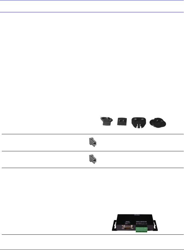
1 box |
Power adapter with plugs for |
|
Plug adapters depend on local electrical current. Four |
|
100-240 VAC, 12 VDC, 50-60 HZ, |
models are included: |
|
|
1 A, 12 W |
|
• CEE 7/16 (Europlug 2.5 A/250V unearthed) |
|
|
|
• NEMA 1-15 (North American 15 A/125V ungrounded) |
• BS1363 (British 13A /230-240V 50 Hz earthed and fused)
• CPCS-CCC (Chinese 10 A/250V)/AS 3112 ; Australian 10 A/240V).
1Connector adapter, RJ45 to DB9 male, for RS422
Backwards compatibility with VideoBloX and VideoBloX Lite CPU installations. VideoBloX master port.
2Connector adapter, RJ45 to DB9 female, for RS232
Backwards compatibility with MAXPRO-Net CPU installations.
2 |
RJ45 network cable, 2 meters |
All installations. |
|
|
|
1 |
RJ45 cross-over Ethernet cable, 2 |
Used to connect a PC directly to the Controller for web |
|
meters, blue |
browser configurations. |
|
|
|
1 |
RJ11 4X6 flat ribbon cable, 2 meters |
To connect from a MAXPRO and MX18 to the UltraKey Lite. |
|
|
|
1 |
Function key overlay |
For use with VideoBloX installations. |
|
|
|
1 |
Terminal box |
For additional device connection requirements. |
18
UltraKey Lite Controller Installation and User Guide
UltraKey Lite Port Connections and Descriptions
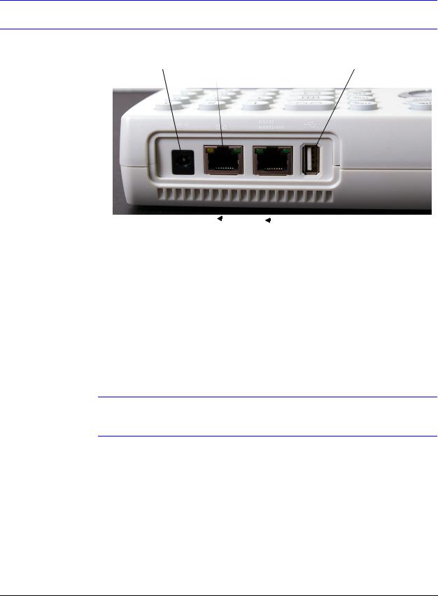
Figure 1-1 UltraKey Lite Port Connections
Power |
RJ45 |
RS232 and RS422/485 |
USB |
|
Ethernet |
Serial port |
|
8 |
|
|
|
1 |
8 |
|
|
1 |
|
||||||||
|
|
|
|
|
Pins numbered from right to left
DC Power Port
Supports 12V (±10%) DC/1 A power input. Use the power adapter included with the shipment and insert one of the four adapters based on your local power requirements.
Ethernet Port
Note Ethernet is used to connect to the controller web browser, MAXPRO-Net or
VideoBloX NetCPU.
•10/100M Ethernet PoE (power over Ethernet) input. If PoE is the power input, it is not recommended to connect this network with an outside building.
•TCP/IP protocol on the controller.
•For VideoBloX, the controller address range can be between 1 and 32. For MAXPRO-Net, the address range can be between 1 and 99.
Document 800-07422 Rev A |
19 |
08/10 |
|
About this Document and the UltraKey Lite
RS232, RS422/485 Serial Port
Note These ports are used to connect to MAXPRO-Net RS232 or RS422 and to
VideoBloX NetCPU, Standard CPU and Lite CPU RS422.
An isolated surge protection is suggested when using RS485/RS422 and when cabling between buildings.
Note For MAXPRO net installations, COM1 (RS422) and COM2 (RS485) are configured using the controller LCD menu and cannot be used at the same time.
Note Serial port 1 can be either RS485 or RS422. Serial port 2 is only RS232.
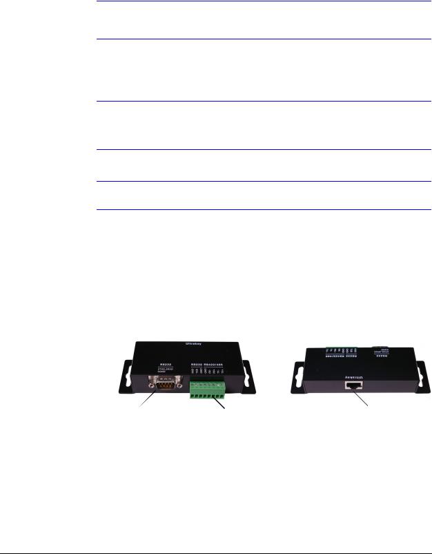
Terminal Box
Use the terminal box RJ45 port and 8-pin terminal plug as required for compatibility and connectivity options. It can be used to break out the RJ45 cable when wiring to existing infrastructure is required.
Figure 1-2 Terminal Box Front and Back Ports
RS232 DB9 |
RS232 and RS422/485 8-pin |
RJ45 Ethernet |
Serial port |
Terminal plug (pin numbers can |
|
|
be assigned by user) |
|
USB Port
The USB port is not used with VideoBloX or MAXPRO-net.
20
2
Using the UltraKey Lite Controller
You may need to learn how to use the UltraKey Lite both before and after you begin configuring. In this section:
•Logging Onto the Controller, page 21
•Using the UltraKey Lite to Navigate the LCD Menus, page 22
•VideoBloX Key Functions, page 24
•MAXPRO Key Functions, page 27
Note Key availability is dependent on the mode selected. Functions only used with the Standalone Mode (for PTZ/DVR functions) are not described in this document and will be included in future releases.
Logging Onto the Controller
1.Connect the keyboard with a power adapter (12V (±10%) DC/1 A included) or a network cable with PoE.
2.To configure the main menu settings, press Alt > Clr.
3.Enter the PIN password 3434.
Note If an invalid password is entered, a message displays and the controller buzzes. Repeat the steps to log on.
When you are in the Password menu, press Alt > Clr again to exit the
Password menu.
Document 800-07422 Rev A |
21 |
08/10 |
|

Using the UltraKey Lite Controller
Using the UltraKey Lite to Navigate the LCD Menus
There are a variety of ways to navigate both the LCD menus during configuration and set up as well as during normal operation with your matrix system. Figure 2-1 shows all of the keys and other elements of the UltraKey Lite controller. See Table 2-2 for UltraKey Lite key functions when used with a VideoBloX system. See Table 2-3 for UltraKey Lite key functions when used with a MAXPRO-Net system.
Figure 2-1 UltraKey Lite Controller Keyboard Layout
|
|
1 |
|
|
|
|
4 |
6 |
8 |
|
10 |
12 |
14 |
|
|
|
|
|
|
|
|
|
|
|
|
|
|
||||||
|
|
|
|
|
|
2 |
3 |
5 |
|
7 |
9 |
11 |
13 |
15 |
|
|
|
|
12:00 |
4/6/09 |
|
|
|
|
|
|
|
|
|
|
|
|
|
|
Menu Setup Down |
|
|
|
|
|
|
|
|
View |
1 |
2 |
3 |
|||
|
|
|
|
|
|
|
|
|
|
|
|
|
||||
31 |
|
|
|
|
|
Alarm |
Seq |
Set |
|
Review |
|
Search |
Tour |
4 |
5 |
6 |
|
|
|
|
|
|
|
|
|
||||||||
|
|
|
|
|
|
|
|
|
|
|
|
|
|
|||
|
|
|
|
|
|
+ |
|
+ |
+ |
|
|
|
|
|
|
16 |
|
|
|
|
|
|
|
Iris |
|
|
|
PTZ |
7 |
|
|||
|
|
|
|
|
|
|
|
|
|
|
|
8 |
9 |
|||
|
|
|
|
|
|
Focus |
|
— |
Focus |
|
|
|
call |
|||
|
F2 |
|
|
|
F5 |
— |
|
— |
|
|
|
|
|
|
|
|
F1 |
F3 |
F4 |
|
|
|
|
|
|
|
0 |
|
|||||
30 |
|
|
|
|
|
|
|
|
|
|
|
|
Alt |
Clr |
Ent |
|
|
|
|
|
|
|
|
|
|
|
|
|
|
|
|
|
|
F6 |
F7 |
F8 |
F9 |
F10 |
|
|
|
|
|
|
|
|
|
|
|
|
29 |
28 |
27 |
26 |
25 |
24 |
23 |
21 |
20 |
18 |
17 |
|
|
|
|
|
|
22 |
|
|
19 |
|
See Figure 2-2 for a brief overview of the three main navigation options. See Table 2-1 for specific methods to navigate the LCD during installation and set up.
22
Loading...