


TrueSTEAM™ |
|
|
|
|
|
|
|
™ |
|||
|
|
|
|||
|
|
||||
|
PROFESSIONAL INSTALLATION GUIDE |
||||
Included in this Humidifier Box
E
TrueSTEAM
G |
|
Homeowner’s Operating Manual |
|
|
|
Must be installed by a trained, experienced technician |
I |
||
H |
Read these instructions carefully. Failure to follow these instructions |
|||
can damage the product or cause a hazardous condition. |
|
|||
F |
|
|
|
|
|
|
|
|
|
|
|
|
|
|
|
J1 |
J2 |
J3 |
J4 |
|
|
|
|
|
|
|
|
|
|
|
|
|
Tools needed to install Truesteam
 Wire cutter/stripper
 1-3/4-in. diameter hole saw
 1/8-in. drill bit
 Standard screwdriver
 18-gauge wire (up to 5 conductor)
 Torx driver T-20 and T-30
Other Requirements
TrueSTEAM flushes water at or above 140°F (60°C). Refer to local codes for proper draining practices for hot water.
 Condensate pump rating of 212°F (100°C) if used.
Drip pan with water sensor shut-off required underneath TrueSTEAM if installed in or above finished space.
TrueSTEAM
Mounting bracket and hardware Water filter and backflow preventer Saddle valve
EWater supply hose
FDrain hose (10 feet)
GDuct nozzle and gasket
HOwner’s manual
I Service label
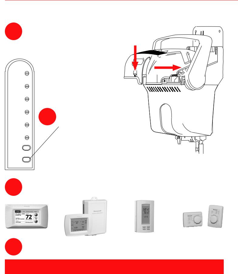
J1 Prestige HD color control* J2 TrueIAQ control*
J3 Humidity control*
J4 VisionPRO IAQ control*
* Control based on model ordered.
Remote installation requires separate purchase of the Honeywell Remote Mounting Kit (#50024917)
69-2285EFS-03

Installation Guide |
|
Table of Contents |
|
Setting Homeowner Expectations. |
................................................ 1 |
Mounting.......................................................................................... |
3 |
Plumbing.......................................................................................... |
5 |
Wiring............................................................................................... |
7 |
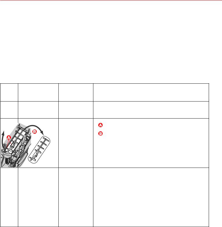
Maintenance.................................................................................. |
15 |
Troubleshooting............................................................................. |
18 |
Parts List........................................................................................ |
22 |
Appendix A - Remote Installation................................................ |
23 |
Appendix B - Advanced Wiring.................................................... |
25 |
Appendix C - Remote Draining.................................................... |
27 |
Need Help?
For assistance with this product please visit http://yourhome.honeywell.com or call Honeywell Customer Care toll-free at 1-800-468-1502
Read and save these instructions.
® U.S. Registered Trademark. Patents pending.
Copyright © 2009 Honeywell International Inc. All rights reserved.
69-2285EFS—03 |
ii |

TrueSTEAM Humidification System
What to Expect
•It may take up to a week of continuous operation to achieve the humidity set point, depending on weather, size of home, furnishings in the home, insulation, etc.
•35% relative humidity in a typical winter humidifier market is considered ideal by industry experts. Homeowner can adjust to their own comfort or until there is condensation on the windows. Lower the setpoint if there is condensation.
•If TrueSTEAM is not humidifying but the humidity is below the setpoint, it is likely the humidity control has a frost protection setting, or TrueSTEAM is in a drain cycle mode.
•Excessive ventilation will exhaust humidified air outside and replace it with dry air, making it difficult to maintain humidity set point under certain conditions. If installing a ventilator, a solution that retains moisture, such as an Energy Recovery Ventilator (ERV), is preferable for maintaining indoor humidity set points.
•If the home can’t achieve the setpoint, the unit may be under-sized for the home. This can be due to insulation, windows, arid climate, etc. or the outdoor temperature may be too low to maintain adequate humidity levels. Honeywell recommends waiting for the outdoor temperature to moderate closer to 20°F (-6°C). If the selected humidity levels are not achieved, then a larger capacity model may be needed.
•At startup, it is normal to experience a slight plastic odor in the home, depending on the amount of ventilation. If the remote hose is used, there may be a slight rubber odor. These odors will dissipate within days of installation.
•If the PRESS EMPTY light is blinking, clean TrueSTEAM per the steps found in the maintenance section. TrueSTEAM will continue to humidify as normal while PRESS EMPTY is blinking.
•The home’s water hardness will determine how often TrueSTEAM needs to be cleaned and how often the included water filter needs to be replaced.
•Data shows there may be a slight increase in the homeowner’s energy consumption when operating any humidifier. However, TrueSTEAM will make the home feel warmer, allowing the homeowner to lower the temperature setting on the thermostat. Every degree lower on the thermostat can save up to 3% on heating costs.
1 |
69-2285EFS—03 |

Installation Guide
Contractors: important installation Requirements
Failure to comply will result in voided warranty, improper installation, and service callbacks.
•Do not direct the steam nozzle at people.
•Water inside tank can be very hot. Explain this to homeowner and emphasize the warning label on TrueSTEAM.
•Do not cut into any air conditioning or electrical line
•Wear safety glasses while installing TrueSTEAM.
•Mount the humidifier in a level position to avoid water damage or heating element failure.
•Install TrueSTEAM on the supply duct. Remotely mount TrueSTEAM to the supply duct if direct mount is not possible.
•Do not install the steam nozzle into supply duct with static pressure exceeding 0.5 in. w.c.
•If remotely mounting TrueSTEAM, refer to the remote mount guide (69-2317) for further instructions.
•Do not install the humidifier where the ambient temperature is lower than 32°F (0°C) or higher than 104°F (40°C).
•Condensate pump must be rated at 212°F (100°C).
•Consult local plumbing codes for drain size, material, and maximum temperature allowed.
•If TrueSTEAM location is in or above finished space, install a drip pan with a wet switch under TrueSTEAM, the water filter, and backflow preventer.
•Do not install the humidifier nozzle through wooden sidewalls (e.g., floor joist).
•The mounting area must be strong enough to support the humidifier’s weight when it is full of water (up to 15 lbs.).
•If the ducting has exposed insulated materials on the interior, ensure the nozzle extends beyond the insulation by clearing away excess insulation at the insertion point, or replace a section of insulated duct (approximately 6 in. x 6 in.) with rigid, non-insulated sheet metal.
•Allow at least 4 inches of clearance between the TrueSTEAM nozzle outlet and any interior duct to avoid condensation forming.
•Mount TrueSTEAM where the nozzle outlet has a minimum of 24 inches of downstream open air space.
•Do not install in completely enclosed spaces, such as a cabinet or unventilated closet. Choose a location that is well ventilated.
•Allow at least 1 foot clearance to ventilation holes in humidifier’s cover. Do not cover these holes. Covering them can increase the internal operating temperature of the humidifier and shorten the humidifier’s life.
•Do not mount directly to duct board. Remote mount nozzle attachment allowed only with a Honeywell duct board adapter kit.
•If used near a pool or spa, ensure the TrueSTEAM can not fall into the water or be splashed. Also, ensure the
TrueSTEAM is plugged into a GFI ground fault interrupt outlet.
Safety Precautions
CAUTION: Voltage Hazard.
Can cause electrical shock or equipment damage. Disconnect HVAC equipment before beginning installation.
Warning: Electrocution, Heavy Equipment, and Water Hazard.
Can cause death, blindness, water damage to home and heating element failure.
Warning: Steam Condensation, Fire, and Freezing Water Hazard.
Can cause failure of fan or limit control or result in water damage to home.
69-2285EFS—03 |
2 |
TrueSTEAM Humidification System
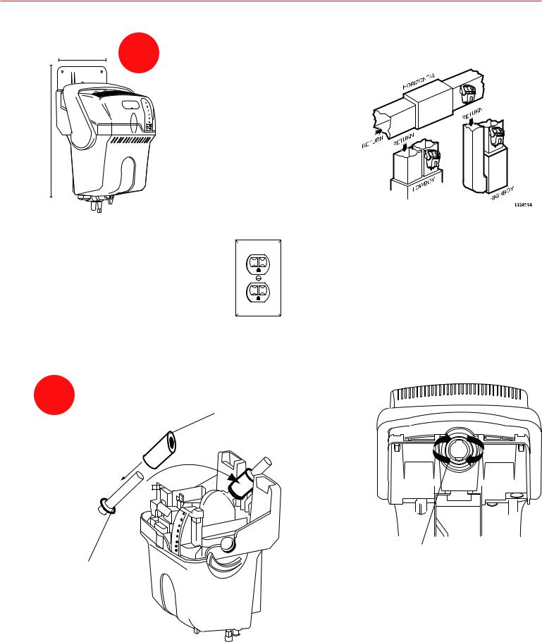
DUCT mount installation
Choose a location that has access to a:
11.5 in. |
1 |
• Drain with a high-temperature water |
|
||
|
|
rating. Refer to local plumbing codes |
|
|
to ensure proper draining. |
• Cold water supply line must be used.
19 in. |
• Electrical circuit rated to your |
humidifier. |
• Vertical surface with adequate clearances.
M28711
|
|
|
|
|
Required Minimum |
|
|
|
|
|
|
|
|
|
|
Model |
Circuit Capacity |
|
|
|
|
||
|
|
|
|
|
|
|
|
|
|
HM506 |
7 Amps |
|
|
|
|
HM509 |
10 Amps |
|
|
|
|
||
|
|
|
|
||
|
|
|
|
HM512 |
12 Amps |
M24745
2Install duct nozzle.
Slide foam gasket down over nozzle.
Ensure o-ring gasket is properly seated in the groove.
M24894
Insert nozzle and twist clockwise to ensure tight seal of nozzle to TrueSTEAM.
M24746A
3 |
69-2285EFS—03 |
Installation Guide
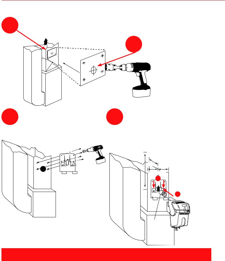
DUCT mount installation
3Position template on supply duct. Ensure proper clearances from A-coil.
SUPPLY
4 |
Drill 1-3/4-in. hole. |
|
|
|
|
|
|
|
|
|
|
M24748A |
5 |
Secure bracket to duct using |
6 |
A) Ensure foam gasket is positioned |
provided self-drilling sheet metal |
correctly over nozzle and insert the |
||
|
screws (4). |
|
nozzle into duct hole. |
B) Push down to secure humidifier to bracket arms. Ensure gasket forms tight seal in duct hole.
Allow 4 in. clearance from nozzle outlet to any duct wall,
24 in. |
and allow 24 in. of |
|
4 in. |
downstream open |
|
duct air space |
||
|
||
4 in. 4 in. |
to prevent duct |
|
B |
condensation. |
|
|
A |
M24749
Foam gasket
M24750A
FOR REMOTE INSTALLATION, REFER TO APPENDIX A OR
DOCUMENT 69-2317, INCLUDED WITH REMOTE MOUNT KIT.
69-2285EFS—03 |
4 |
|
|
TrueSTEAM Humidification System |
|
|
|
|
|
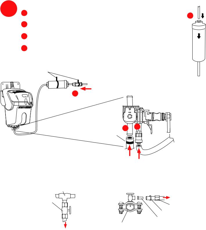
Water Supply Connection |
Use only cold water. Do not use hot water supply. |
||
7 A |
Water Filter. Insert 1/4-in. copper or plastic water line. |
|
|
Apply modest pull to ensure a tight fit. |
A |
|
|
|
BBack-flow preventer valve. Insert 1/4-in. copper or plastic water line. Apply modest pull to ensure a tight fit.
C Connect 1/2-in. drain tube. Secure drain tube to barbed fitting with hose clamp.
DShut off the water supply. Secure 1/4-in. copper or plastic water feed tube.
Support weight with clamps or ties.
M27411
 From cold water supply
B
1/4-in. copper or plastic
Enlarged view
C D
Clamp
1/2-in. drain tube
M27428
1/4-in. water line (plastic provided; copper also acceptable)
Water line tapping options: Refer to selected valve’s literature and to local plumbing codes for proper technique for the selected option.
T-fitting |
Saddle valve (provided) |
|
|
|
To humidifier |
Manual shutoff |
|
Compression nut |
valve (sold |
|
|
|
Ferrule |
|
separately) |
|
|
|
Brass eyelet |
|
|
|
|
To humidifier |
Water supply line |
M24852A |
|
5 |
69-2285EFS—03 |

Installation Guide
Drain Connection
11.5 in.
19 in.
Consult local plumbing codes before installing
8drain.
Ideal installation is direct to main floor drain using the provided rubber hose.
If direct floor drain access is not available, refer to Appendix C.
Secure hose with clamp
Install drain hose with continuous downhill slope.
CAUTION
Hot water may exit drain and can cause burns from scalding.
M24744A
Draining water may be hot. Direct and secure the hose outlet into the floor drain to reduce risk of hot water pooling or splashing. Consult and follow local plumbing codes for drain pipe size and maximum temperature requirement.
69-2285EFS—03 |
6 |
TrueSTEAM Humidification System
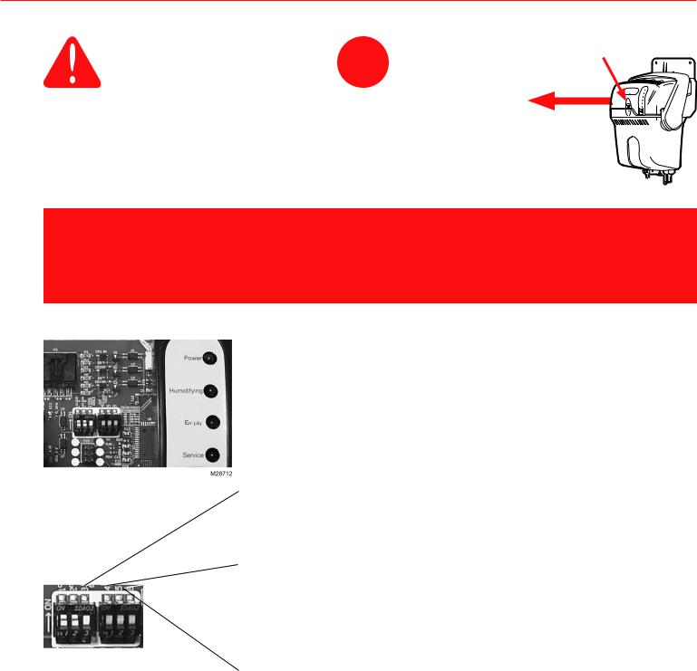
CAUTION: Voltage Hazard.
Before wiring to HVAC terminals, disconnect HVAC equipment power. Ensure humidifier is not plugged in.
wiring–Getting Started
9Loosen captive cover screw. Slide cover out from front.
M27733
BEFORE YOU GET STARTED
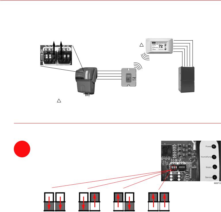
TrueSTEAM wiring is different from evaporative pad humidifier wiring. TrueSTEAM is able to monitor system power, and regulate system fan operation, in addition to solenoid water valve actuation. These wiring features are configured by DIP settings.
DIP Settings for TrueSTEAM Humidification
With the TrueSTEAM cover removed, you will see six DIP switches to the left of the interface panel. This manual refers to
DIPs 1-6 from left to right. DIP 3, 4 and 5 offer different wiring configurations for how to humidify. (DIPs 1-2 are associated with maintenance. Details for DIPs 1-2 are found in the maintenance section.) DIP 6 is not used at this time.
DIP 3 = Wireless operation (applicable only on wireless models)
If DOWN (default) wireless terminal is disabled.
If UP, wireless terminal is enabled.
DIP 4 = Power monitoring.
If DOWN (default), TrueSTEAM looks for R input before allowing humidity.
If UP, TrueSTEAM does not look for R input before allowing humidity. Power is still allowed to pass through if R is wired.
M28683 |
DIP 5 = Back-up air proving. |
|
|
|
If DOWN (default), TrueSTEAM does not look for air |
|
movement (via air proving device) before allowing humidity. |
|
If UP, TrueSTEAM looks for air movement (via air proving |
|
device) before allowing humidity. Wire an air proving device |
|
between TrueSTEAM C and System C. |
|
Note: Setting DIP 5 up requires DIP 4 to be down. If DIP 4 is up, |
|
DIP 5 position will not be used. |
7 |
69-2285EFS—03 |
Installation Guide
wiring–Getting Started
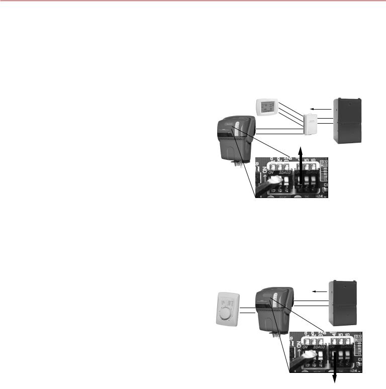
Power Monitoring is a configuration that allows TrueSTEAM to only allow humidity to enter the duct when it receives confirmation that the HVAC system transformer has power.
There are two ways power monitoring can be configured, depending on what humidity control is used.
Note: This image is not a complete wiring diagram.
It only depicts power monitoring.
1.Using a thermostat with integrated humidity control, such as VisionPRO IAQ or Prestige.
•A thermostat is powered by the system transformer, so if it does not have power, the humidifier will not be able to produce steam.
•Because the thermostat knows when the system transformer has power, set TrueSTEAM DIP 4 to UP, so that it is not also looking for an R input from the system R.
Ideal for Contractors Who
1 |
|
2 |
|
3 |
R |
C
HUM
HUM
DIP 4
M28684
-Want simplified accessory wiring (TrueSTEAM only
needs to be connected to the HUM terminals from the control).
-Provide integrated system and accessory controls in the living space to their customers.
Note: This image is not a complete wiring diagram.
It only depicts power monitoring.
2.Using a humidistat SEPARATE from the thermostat, such as H8908 or TrueIAQ.
•TrueSTEAM generally supplies power to a humidistat. It is important that TrueSTEAM monitor HVAC system power to determine if humidity is allowed.
•Leave DIP 4 in the DOWN position (factory setting), and wire the HVAC system R and C to the
TrueSTEAM R and C. TrueSTEAM will verify power is present before allowing steam production.
R
HUM C HUM
DIP 4
M28685
Ideal for Contractors Who
-Use a humidity control separate from the thermostat system control.
69-2285EFS—03 |
8 |
TrueSTEAM Humidification System
wiring–Getting Started
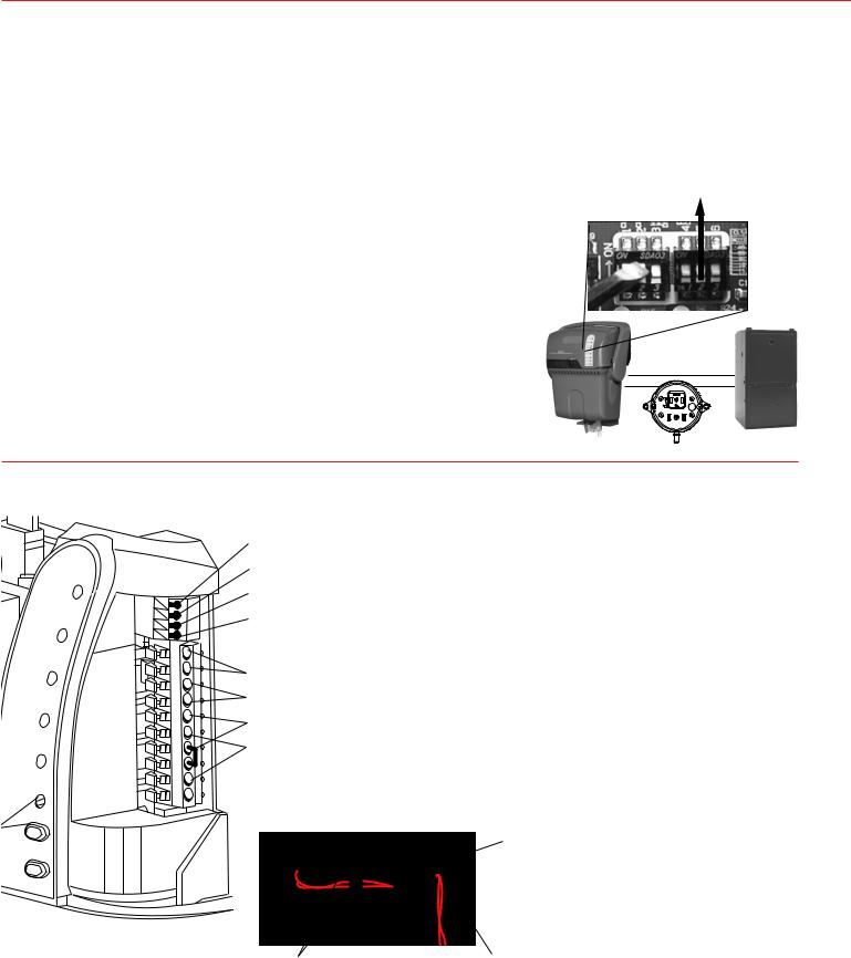
System Fan Regulation is a configuration that allows TrueSTEAM to monitor the HVAC system’s fan operation, and ensure that the fan is on if humidity is needed. Airflow is needed to distribute humidity into the living space, and prevent condensation from forming in the duct.
There are two ways system fan operation can be configured, depending on what humidity control is used.
Note: This image is not a complete wiring diagram. It only depicts fan regulation.
1.Using a thermostat with integrated humidity control, such as VisionPRO IAQ or Prestige.
•A thermostat controls the fan and humidifier, so the control will not allow steam production without turning the system fan on.
•Wire thermostat G to the HVAC system G as normal.
Wire TrueSTEAM HUM terminals to the system HUM terminals.
1 |
HUM, G |
SIGNAL |
|
2 |
|
|
|
3 |
|
1 |
|
|
|
|
|
|
|
|
|
G |
|||
|
|
|
|
|
|
|||
|
|
|
|
2 |
|
|
||
|
|
|
|
|
|
|
|
|
|
|
|
HUM |
3 |
|
|
|
|
|
|
|
|
|
|
|
|
|
|
|
|
HUM |
|
|
|
|
|
|
|
|
|
|
|
|
|
|
M28686
Ideal for Contractors Who
-Want integrated control of the humidifier and HVAC system in the living space.
-Want the system fan to turn on immediately upon a call for humidity.
Note: This image is not a complete wiring diagram.
It only depicts fan regulation.
2.Using a humidistat SEPARATE from the thermostat, such as H8908 or TrueIAQ.
•External humidity controls do not monitor or control the system fan, so it is critical that TrueSTEAM ensures the fan has power before allowing humidity.
•Break the thermostat G to HVAC system G connection.
Wire thermostat G to TrueSTEAM GT. Wire TrueSTEAM GF to HVAC system G.
|
|
|
|
|
G |
1 |
|
|
|
|
||
|
|
|
|
|
|
|
|
|
||||
|
|
|
|
|
GT |
|
|
|
|
|||
|
|
|
|
|
|
|
|
|
|
|
|
|
|
|
|
|
|
|
|
|
|
R |
R |
||
|
HUM |
|
|
|
|
RT |
|
|
|
|||
|
HUM |
|
|
|
|
|
|
|
|
|
||
|
|
|
|
|
GF |
G |
||||||
|
|
|
|
|
|
|
|
|
||||
|
|
|
|
|
|
|
|
|
|
|
|
|
Thermostat G calls will pass through TrueSTEAM |
1 IF THERMOSTAT G SIGNAL IS NOT PRESENT, THEN THE |
|
unhindered. If this signal is not present, and humidity is |
TrueSTEAM GF TERMINAL WILL ENERGIZE THE HVAC G |
|
TERMINAL TO TURN ON FAN. |
M28687 |
|
needed, TrueSTEAM will relay power from its RT terminal
to GF and out to HVAC system G to ensure the fan has power for humidity calls
Ideal for Contractors Who
-Use a humidity control separate from the thermostat.
-Wish to avoid excessive air circulation in the home. TrueSTEAM fan calls will not be sent out of GF until the water temperature reaches 170°F (just before boiling).
Note: This feature can be used with VisionPRO IAQ as well. See page 13.
9 |
69-2285EFS—03 |
R
C
1 |
C |
1 |
|
2 |
3 |
2 |
3 |
|
|
2 |
|
NO
+ PI
IN MEXICO
ASSEMBLED
3 NC
M28688
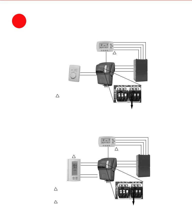
24V 24V HUM HUM C GT R RT GF EXT
24V |
AC output voltage |
HUM |
Low-voltage terminals for humidity control. |
C, R |
Inputs from HVAC system transformer. |
GT, GF GT input is from thermostat G. GF output goes to HVAC system G.
|
|
Route wires through the raised |
|
|
tabs and out the notch at the rear |
|
|
of the chassis. Ensure wires are |
|
|
secure and do not interfere with |
M27732 |
M24893 |
assembly of cover. |
|
|
|
Tabs |
|
Notch |
69-2285EFS—03 |
10 |
TrueSTEAM Humidification System
BAsic WIRING
10 |
Wire the TrueSTEAM according to the diagram that applies to your humidity |
control. |
Dry-contact mechanical humidistat wiring.
|
R |
|
CONVENTIONAL |
C |
|
W |
|
|
THERMOSTAT |
|
|
Y |
|
|
|
|
|
G |
1 |
|
|
|
Y W C R |
GT |
|
|
|
R |
|
|
C |
|
HUM |
GF |
G |
|
|
|
HUM |
|
|
H8908
1ENSURE THERMOSTAT ISOLATES Y FROM G. ALL HONEYWELL PRESTIGE, VISIONPRO IAQ, VISIONPRO, AND FOCUS PRO THERMOSTATS DO THIS.
DIP4
M28689
TrueIAQ wiring.
|
|
R |
|
CONVENTIONAL |
C |
||
THERMOSTAT |
W |
||
|
|
Y |
|
|
G |
1 |
|
|
|
Y W C R |
|
2 |
GT |
|
|
|
|
||
R |
24V |
R |
|
C |
|||
C |
24V |
||
GF |
|||
|
|
||
HUM HUM
HUM HUM
TrueIAQ
1ENSURE THERMOSTAT ISOLATES Y FROM G. ALL HONEYWELL PRESTIGE, VISIONPRO IAQ, VISIONPRO, AND FOCUS PRO THERMOSTATS DO THIS.
2 IN TRUEIAQ INSTALLER SETUP, SET ISU # 25 TO 3. |
DIP4 |
M28690
11 |
69-2285EFS—03 |
Installation Guide
BASIC wiring
VisionPRO IAQ™ Wiring
Follow this diagram if using VisionPRO IAQTM with TrueSTEAM’s fan-delay feature. The system fan will turn on when the tank’s water temperature is 170°F.
1
1
2
3
P 4 |
|
1 |
|
|
|
2 |
C |
||
|
|
|||
|
|
3 |
||
GT |
G |
Y |
||
|
||||
|
W |
|||
HUM |
HUM |
|
||
|
|
|||
HUM |
HUM |
|
|
|
R |
|
|
R |
|
GF |
|
|
G |
1 IN VISIONPRO IAQ INSTALLER SETUP,
SET ISU # 0374 TO 3. |
M28691 |
|
Follow this diagram if using VisionPRO IAQTM to turn system fan on immediately with humidity call.
P 4
|
|
|
|
W |
|
|
|
|
|
|
G |
|
|
1 IN VISIONPRO IAQ INSTALLER SETUP, |
|
|
|
|||
SET ISU # 0374 TO 1. |
|
|
|
|
|
M28692 |
1 |
|
|
|
|
|
|
1 |
|
|
|
|
|
|
2 |
|
|
|
|
|
|
3 |
|
|
|
|
|
|
|
1 |
|
|
|
|
|
|
2 |
|
|
R |
||
|
3 |
|
|
C |
||
HUM |
HUM |
Y |
||||
HUM |
HUM |
|
|
|
||
69-2285EFS—03 |
12 |
TrueSTEAM Humidification System
WirELESS INSTALLATION
RedLINK Prestige HD connection.
R
C
1 W Y
G
G Y W C R
A A
B B
C C
D D
1 "1" IN PRESTIGE INSTALLER SETUP, PROGRAM HUMIDITY CALLS TO "HUMIDIFY FORCES FAN ON." |
M28694 |
Configuring Flush Cycles
11 |
DIP 1 and DIP 2 configure how frequently TrueSTEAM will |
automatically flush minerals from its tank. |
|
|
Note: Flush timing is based on hours of active heating |
element time, not real time.
1 2 |
1 2 |
1 2 |
1 2 |
ON
OFF
8-HOUR FLUSH |
12-HOUR FLUSH |
20-HOUR FLUSH |
30-HOUR FLUSH |
(FACTORY |
|
|
|
SETTING) |
|
|
M28695 |
13 |
69-2285EFS—03 |
Installation Guide
Startup and Checkout
12 |
Slide the cover back into place and secure screw. |
Turn on the water supply. |
POWER
HUMIDIFYING
EMPTY
SERVICE
DRAINING
CLEANING REQUIRED
DRAIN
Plug in the TrueSTEAM power cord. 13 Press/release the GO button to ready
the TrueSTEAM for operation.
TrueSTEAM will ready itself after five minutes if the GO button is not pushed.
M24762
GO
M24763A
Turn the humidity control to the “Test” position. If the “Test” position is unavailable, 14 turn the control to a high setpoint (60% +). Be sure to return the setpoint to the desired
level when testing is complete. “Off” will turn TrueSTEAM off.
15 |
Confirm that the furnace blower turns on to circulate air. This will take 10–15 minutes |
after the call for humidity if TrueSTEAM is controlling the fan. |
Allow TrueSTEAM to produce steam, then check all water line connections to ensure there are no leaks before leaving the job site.
69-2285EFS—03 |
14 |
TrueSTEAM Humidification System
Maintenance
TrueSTEAM will automatically flush itself during the humidification season. It is recommended that TrueSTEAM be manually cleaned at least once every 5 months (hard water may require more frequent cleaning).
The ‘Cleaning Required’ Light

 GO
GO

M28696
 TrueSTEAM’s ‘Cleaning Required’ light will turn on to indicate the tank needs manual cleaning. TrueSTEAM will still operate as normal with the ‘Cleaning Required’ light on. Follow steps 1-10 below to clean TrueSTEAM.
Note: The ‘Cleaning Required’ light will turn on if the tank drains too slowly during its automatic cleaning cycle, likely due to tank sediment. TrueSTEAM will still operate as normal, and if during the next automatic cleaning cycle the tank drains normally, the ‘Cleaning
Required’ light will turn off.
Warning: Scalding hazard.
Do not attempt to remove the humidifier from the mounting bracket during operation, or when the humidifier’s water tank is full of water. The heating element could be hot when tank is removed. Failure to comply could result in severe scalding.
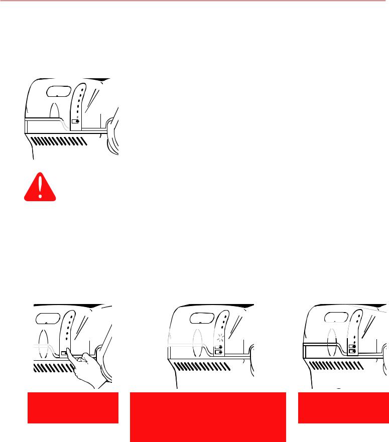
Drain Operation
During auto flushing, cold water will enter the tank to lower water temperature below 140°F
(60°C) before draining.
Flush Override Caution: A standard flush takes up to 45 minutes. If you press/hold the DRAIN and GO buttons after the “Draining” light is already blinking, the tank will empty immediately, regardless of water temperature. Make sure the drain can handle up to 212°F if you do this.
1. To manually clean TrueSTEAM:
 DRAIN
DRAIN

M24774A
PRESS AND HOLD DRAIN BUTTON
DRAINING  (BLINKING LIGHT)
M24775A
TANK FLUSHING
Pressing DRAIN and GO buttons after Draining light is blinking will empty the tank regardless of water temperature.
Use caution.
EMPTY  (ON SOLID)
M24776A
TANK EMPTY
Proceed to steps 2-4.
15 |
69-2285EFS—03 |
Installation Guide
Maintenance
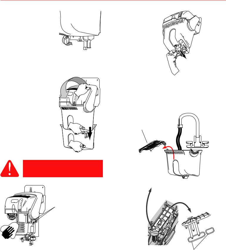
2.When tank is empty, turn the manual shut-off valve at the bottom of the tank to “Unlock”.
4.Firmly grip the tank bottom. Push down the cover's safety button and pull the latch forward to release the tank.
Note: Latch does not come off humidifier with tank.
3. Grip the white water valve arm and push it back to disengage from the tank’s black spool.
M24777
M24779
5. Use tap water to flush loose minerals from the tank. Sediment screen at tank's bottom is removable. For a more thorough cleaning, soak tank in warm, soapy water, then rinse clean. Tank is also dishwasher-safe.
Note: Do not use hydrocarbon oil-based cleaners.
Sediment screen
M24778
Caution
For steps 6–7, unplug TrueSTEAM.
6. Carefully rub minerals off of the heating element and tank walls.
Clear sensor compartment holes of debris if present.
7. Remove TrueSTEAM cover. Inspect water level sensor. If debris buildup is present, replace.
M24857
M24856
Remove T-30 Torx screw and lift clamp.
Remove
M28710
Ensure sensor gaskets are seated properly and are in good condition (no cracks).
69-2285EFS—03 |
16 |

TrueSTEAM Humidification System
Maintenance
8. Replace inline filter at least once per season. Turn water supply off before replacing.
Press down filter collar ring and pull out 1/4 in. water line from each side.
Insert 1/4 in. lines into new filter. Apply modest pull to ensure a tight fit.
M28697
9.Once clean, reattach tank by securing the latch. Engage the white water valve to the tank’s black spool, and “Lock” the shut-off valve.
The “Press Reset” light will blink at start-up. Push the RESET button to ready the humidifier.
10.
•Clear any dust from the ventilation holes in the humidifier’s cover.
•Clear any debris from the water drain tube.
•Make sure the water tank gasket seal is seated properly in the humidifier base, and is in good condition (no cracks or tears) before reattaching the humidifier water tank.
•Check that the humidifier is still mounted level.
Automatic End of Season Shutdown
M27411
M28698
TrueSTEAM has the intelligence to empty the tank when humidity is not needed for an extended period. After 48 hours of inactivity, TrueSTEAM will drain and remain empty until humidity is needed again. This prevents water from stagnating within the tank. The tank will refill with water upon next humidity call.
Extended Vacation
It is recommended you turn off the humidifier’s water supply and turn off the humidity control for extended leaves. When you return, turn on the humidifier water supply and reset the humidity control to a comfortable position.
17 |
69-2285EFS—03 |
Installation Guide
Troubleshooting
TrueSTEAM has internal system diagnostics that monitor system operation, maintenance schedules, and faults. If a system fault is detected, the system will attempt to recover itself up to five times in a 24 hour period. If unable to recover in that time, the red Service light will activate.
If the TrueSTEAM Service light is blinking, a system fault has occurred from which the humidifier can not recover by itself. The table below shows the possible faults, along with steps to fix
TrueSTEAM.
If the red Service light is on, count the number of blinks between pauses. Refer to the table below for the fault signified by the number of blinks that occur. To clear the fault, press and hold the GO button for 5 seconds.
Press/hold the GO button to clear the Service Timer light (i.e. the Cleaning Required light).
No. of |
Fault Description |
Auto- |
Steps to Fix |
|
Red |
|
Recoverable? |
Performed Only by Professional HVAC Technician |
|
Light |
|
|
|
|
Blinks |
|
|
|
|
1 |
Water/Heater temperYes, TrueSTEAM |
• |
Unplug TrueSTEAM and plug back in. |
|
|
ature sensor failed. |
will reset if fault |
• |
Press the GO button. |
|
|
no longer exists in |
• |
If fault returns, replace TrueSTEAM. |
|
|
1 hour. |
|
|
2 |
Water sensors failed. |
Yes, TrueSTEAM |
• |
Unplug TrueSTEAM and remove cover. |
|
|
will reset if fault |
• |
Disconnect water level sensor wiring, remove screen and |
|
|
no longer exists |
|
lift snap-hinge clamp. |
|
|
in 1 hour. Will |
|
Remove water sensor assembly. |
|
|
attempt to reset |
• |
Replace water sensor (#50027998-001). |
|
|
itself 5 times in 24 |
• |
Reassemble the sensor assembly in the unit, replace snap- |
|
|
hours. |
|
hinge, and reattach and secure cover. |
|
|
|
• |
Plug unit back in and press the GO button. |
|
M24901 |
|
|
|
3 |
Failure to fill tank |
Yes, system will |
• |
Ensure inlet water is on. |
|
with water. |
return to “Ready” |
• |
Check for leaks around the tank seal and solenoid. |
|
|
if fault no longer |
• |
Turn off water supply and replace in-line water filter. |
|
|
exists in 3 hours. |
• |
Press/hold GO button until the red Service light turns off. |
|
|
|
• |
If tank still fails to fill, press the DRAIN button (if unit fails to |
|
|
|
|
drain, unplug unit and make sure water in tank is cool). |
|
|
|
• |
Follow this guide’s cleaning steps in the Maintenance |
|
|
|
|
section. Ensure you have a firm grip of the tank prior to |
|
|
|
|
releasing the tank, especially if water is present. |
|
|
|
• |
Clear any excess debris from the tank’s bottom orifice to the |
|
|
|
|
solenoid. |
|
|
|
• |
Reassemble tank and plug unit back in. Press the GO button. |
|
|
|
• |
If water still fails to fill into the tank, replace the solenoid |
|
|
|
|
valve (# 50027997-001). |
69-2285EFS—03 |
18 |
|
|
|
|
TrueSTEAM Humidification System |
|
|
|
|
Troubleshooting |
No. of |
Fault Description |
Auto- |
Steps to Fix |
|
Red |
|
Recoverable? |
Performed Only by Professional HVAC Technician |
|
Light |
|
|
|
|
Blinks |
|
|
|
|
4 |
Heating element |
No |
• |
Follow tank cleaning steps (pages 15–17). |
|
overheated. |
|
• |
Reassemble tank and press the GO button. |
|
|
|
• If fault returns, replace TrueSTEAM. |
|
5 |
Input voltage insuf- |
Yes, system will |
• |
Verify the power circuit is not overloaded. |
|
ficient. |
return to “Ready” |
• |
Unplug and replug the unit in to see if the fault returns. |
|
|
if fault no longer |
• |
If fault returns, unplug unit and remove cover. |
|
|
exists in 1 hour. |
• |
Ensure wiring connections are secure and attached. |
|
|
|
• |
If fault returns, replace the TrueSTEAM with a new one (field |
|
|
|
|
service is not recommended in the event line voltage is lost). |
6 |
Water overflow |
Yes, system will |
• |
Ensure drain hose is not kinked or submerged in water at the |
|
sensed. |
return to “Ready” |
|
drain. Check functionality of condensate pump if used. |
|
|
if fault no longer |
• |
Check for water coming out of drain/overflow line. If |
|
|
exists in 1 hour. |
|
continuous water flow is present, follow the cleaning steps |
|
|
|
|
on pages 15–17. |
|
|
|
• |
Press and hold DRAIN button to drain tank. |
|
|
|
• |
Set humidistat RH setpoint to Test mode. |
|
|
|
• |
If fault returns, unplug TrueSTEAM. |
|
|
|
• |
Loosen cover screw and remove cover. |
|
|
|
• |
Disconnect water level sensor wiring, remove screen and |
|
|
|
|
lift snap-hinge clamp. |
|
|
|
|
Remove water sensor assembly. |
|
M24901 |
|
• |
Replace water sensor (#50027998-001). |
|
|
|
• |
Reassemble the sensor assembly in the unit, replace snap- |
|
|
|
|
hinge, and reattach and secure cover. |
|
|
|
• |
Plug unit in, and press GO button. |
7 |
HVAC power not |
Yes, system will |
• |
Unplug and replug the unit in to see if power returns. |
|
present (monitor this |
return to “Ready” |
• |
If not, ensure HVAC equipment has power. Check circuit |
|
fault only when DIP 4 |
if fault no longer |
|
breaker and replace fuse if circuit is tripped. |
|
and 5 are OFF). |
exists in 1 hour. |
• |
Unplug TrueSTEAM and remove cover. |
|
|
|
• |
Check DIP 4 position and verify correct wiring based on DIP |
|
|
|
|
4 position. See Power Monitoring for more information. |
|
|
|
• |
Plug unit in. |
|
|
|
• If fault reappears, ensure the circuit being used has the |
|
|
|
|
|
rating to support the unit. Unplug any additional equipment |
|
|
|
|
plugged into this circuit. If fault disappears, the circuit |
|
|
|
|
capacity is not properly sized to your unit. |
|
|
|
• If fault returns, replace unit. |
|
8–9 |
The weld monitor |
No |
• |
Press/hold GO to clear service fault. |
|
input is active when |
|
• |
Initiate a humidity call. |
|
the heater relay is off. |
|
• |
If fault returns, replace TrueSTEAM. |
10–11 |
The heater relay failed No |
• |
Press/hold GO to clear service fault. |
|
|
to turn on. |
|
• |
Initiate a humidity call. |
|
|
|
• If fault returns, replace TrueSTEAM. |
|
19 |
69-2285EFS—03 |

Installation Guide
Troubleshooting
No. of |
Fault Description |
Auto- |
Steps to Fix |
|
Red |
|
Recoverable? |
Performed Only by Professional HVAC Technician |
|
Light |
|
|
|
|
Blinks |
|
|
|
|
12 |
Temperature of the |
Yes, system will |
• |
Ensure ventilation holes in the cover are clear of obstruction, |
|
electronic circuit |
return to “Ready” |
|
and that 1 foot of clearance is maintained around the cover’s |
|
board is too high. |
if fault no longer |
|
vent holes. |
|
|
exists in 1 hour. |
• |
Ensure the TrueSTEAM is installed in a location with |
|
|
|
|
conditioned air 32°F (0°C) to 104°F (40°C). |
|
|
|
• |
Turn humidistat off and allow time for electronic board to |
|
|
|
|
cool. This could take up to 2 hours. |
|
|
|
• |
Turn humidistat on and press GO button. |
|
|
|
• |
Confirm humidity call starts by HUMIDIFYING light turning |
|
|
|
|
on. |
|
|
|
• |
Allow unit to run and check for steam leaks around tank and |
|
|
|
|
ventilation holes. |
|
|
|
• If fault returns, replace TrueSTEAM. |
|
13 |
Tank failed to drain. |
No |
• |
Water in tank may be hot (>140ºF [60ºC]). |
|
|
|
• |
Press and hold the DRAIN button. |
|
|
|
• If unit fails to drain, wait for water in tank to cool. Ensure |
|
|
|
|
|
tank water is cool before proceeding. |
|
|
|
• |
Once cool, follow tank cleaning steps (pages 15–17). |
|
|
|
• |
Reassemble tank and press the GO button. |
|
|
|
• If fault persists, replace the solenoid valve (#50027997-001). |
|
14 |
Heater failed to boil |
Yes, system will |
• |
Follow tank cleaning steps (pages 15–17). |
|
water. |
return to “Ready” |
• |
Reassemble tank and press the GO button. |
|
|
if fault no longer |
• |
If fault returns, replace TrueSTEAM. |
|
|
exists in 1 hour. |
|
|
15 |
No Airflow. |
Yes, system will |
• |
Ensure Differential Pressure Switch is installed and wired |
|
|
return to “Ready” |
|
correctly. See the Wiring section for proper wiring. |
|
|
if fault no longer |
• |
Unplug TrueSTEAM and remove cover. |
|
|
exists in 1 hour. |
• |
Ensure DIP switches are set correctly. (DIP 4 down, DIP 5 |
|
|
|
|
up.) |
|
|
|
• If fault persists, replace the air proving accessory being |
|
|
|
|
|
used. |
17 |
Power to the wireless |
Yes, system will |
• |
Unplug TrueSTEAM and remove cover. |
|
adapter overloaded |
return to “Ready” |
• |
Verify wiring between TrueSTEAM and the wireless adapter. |
|
|
if fault no longer |
• |
Ensure DIP switches are set correctly. (DIP 3 up. Also DIP 4 |
|
|
exists in 1 hour. |
|
up if TrueSTEAM R and C aren’t wired.) |
|
|
|
• If fault persists, replace wireless adapter. |
|
18 |
Wireless communi- |
Yes, system will |
• |
Unplug TrueSTEAM and remove cover. |
|
cation from wireless |
return to “Ready” |
• |
Verify wiring between TrueSTEAM and the wireless adapter. |
|
adapter failed. |
after 1 minute. |
• |
Verify Prestige is operating correctly. |
|
|
|
• If fault persists, replace wireless adapter and re-enroll |
|
|
|
|
|
connection to Prestige. |
Cleaning |
Tank was slow to |
N/A |
• |
Follow the cleaning steps in the Maintenance section of this |
Required |
drain during last |
|
|
manual. |
on |
automatic cleaning |
|
|
|
|
cycle. |
|
|
|
|
|
|
|
|
69-2285EFS—03 |
20 |

TrueSTEAM Humidification System
Specifications
Capacity:
HM512: 12 gallons per day (gpd) (45 liters per day [lpd])
HM509: 9 gpd (34 lpd) HM506: 6 gpd (23 lpd)
Humidified Area:
Model |
Cubic Feet Range |
HM512 |
12000–24000 |
HM509 |
8000–18400 |
HM506 |
4000–14400 |
Note: Higher volumes require more TrueSTEAM run time.
Weight:
Model |
Empty |
Filled with Water |
HM512 |
9 lbs. |
15 lbs. |
HM509 |
9 lbs. |
15 lbs. |
HM506 |
8 lbs. |
12 lbs. |
•Dimensions: 11-1/4 in. W x 19 in. H x 9 in. D
•Humidifier Operating Temperature Range: 34ºF–104ºF (1.1ºC–40ºC)
•Remote Hose/Nozzle Operating Temperature Range: -50ºF–250ºF (-46ºC–121ºC)
•Operating Humidity Range: 0–95% RH, noncondensing
Drain Operation
•Auto flushing is configurable to 8, 12, 20 or 30 hours of operational time (heating element active).
•During auto flushing, cold water will enter the tank to lower water temperature below 140ºF (60ºC) before draining.
•During manual flush (performed by pressing the
DRAIN button) initial water temperature may be above 140ºF (60ºC). Ensure drain outlet is not exposed and use caution when pressing the DRAIN button, and do NOT attempt to remove the tank with water in it.
CAUTION
Hot water temperature above 140°F (60°C) can cause burns from scalding.
Standards & Approval Body Requirements
•Flush cycle takes approximately 45 minutes to empty the tank completely.
•Draining Temperature Range: 34ºF–212ºF (1.1ºC–100ºC)
Electrical Ratings and Tolerances
Input Ratings
•Power Supply: 120VAC +10/ -15%, 60Hz
-HM512: 1440W at 120VAC at full load
-HM509: 1200W at 120VAC at full load
-HM506: 840W at 120VAC at full load
•HM512: 12A, 120VAC
•HM509: 10A, 120VAC
•HM506: 7A, 120VAC
•15A, 120VAC interlock switch
•Thermostat/HVAC power monitor (R to C): 10mA resistive at 24VAC
•Field wiring terminals: 18–22 ga. solid
•HVAC power/airflow monitor: 10 mA resistive at 24
VAC
Output Ratings
•Relay output contacts:
-Fan: 1.5A full load, 7.5A locked rotor at 24VAC
-Heat and Backup: 15A resistive at 120VAC
•Fill Solenoid: 0.1A at 120VAC, 0.5 PF
•Drain Solenoid: 0.1A at 120VAC, 0.5PF
•Humidistat output contacts: 10mA resistive at 24VAC
•Humidistat power supply: 100mA at 24VAC
Underwriters Laboratories: UL998, File no. E185662.
Federal Communications Commission: Class B compliance, File no. YU555.
Intended to be used in accordance with the National Electrical Code (NEC), ANSI/NFPA 70, and the rules of the Canadian Electrical Code (CEC), Part 1, C22.1.
21 |
69-2285EFS—03 |

Installation Guide
Parts List
Part |
Part Number |
Fig. Reference |
10-foot Remote Hose and Nozzle Kit |
50024917-001 |
1 |
20-foot Remote Hose and Nozzle Kit |
50024917-002 |
1 |
Cover |
50028004-001 |
2 |
Duct Nozzle |
50028003-001 |
3 |
Remote Nozzles |
50028001-001 |
4 |
Mounting Bracket |
50020012-001 |
5 |
Solenoid Valve |
50027997-001 |
6 |
In-Line Water Filter |
50028044-001 |
7 |
HM512/HM509 Water Tank |
50033181-001 |
8 |
Water Level Sensor Assembly |
50027998-001 |
9 |
Saddle Valve |
32001616-001 |
10 |
Back-flow Water Valve |
50030142-001 |
11 |
Differential Pressure Switch for Air Proving |
50027910-001 |
12 |
Bundled water filter and water level sensor assembly |
50042822-001 |
- |
Sail Switch for Air Proving |
S866A1007 |
- |
Prestige HD Control |
THX9321R5000 |
- |
RedLink Wireless Adapter |
THM4000R1000 |
- |
RedLink Wireless Outdoor Sensor |
C7089R1013 |
- |
VisionPRO IAQ |
YTH9421C1010 |
- |
TrueIAQ |
DG115EZIAQ |
- |
Manual Humidistat |
H8908ASPST |
- |
Ductboard Adapter Kit |
32005530-001 |
- |
|
3 |
4 |
|
|
|
1 |
|
|
|
2 |
|
12 |
|
5 |
|
|
|
|
8 |
|
11 |
|
|
|
|
6 |
10 |
|
|
9 |
|
7 |
|
|
|
|
|
M27735 |
69-2285EFS—03 |
22 |
TrueSTEAM Humidification System
appendIx a: remote InstallatIon
Remote Adapter Nozzle:
Always pitch upward.
Use provided anchors if mounting to drywall or plaster.
TrueSTEAM
TERMINAL
RED
BLACK
GREEN
ORANGE
Diversitech WS-1 wet switch wiring


 24V
24V


 24V
24V


 HUM
HUM


 HUM
HUM


 C
C


 GT
GT

 R
R

 RT
RT


 GF
GF 

 EXT
EXT
DIP |
|
|
|
DIP 5 |
|
|
M28708
If humidifier is in finished space, always install a drip pan with wet switch. Honeywell recommends Diversitech WS-1 (wiring shown here).
23 |
69-2285EFS—03 |
Installation Guide
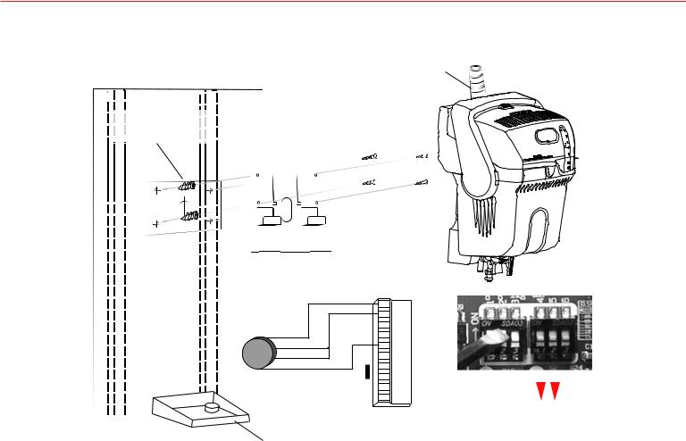
appendIx a: remote InstallatIon
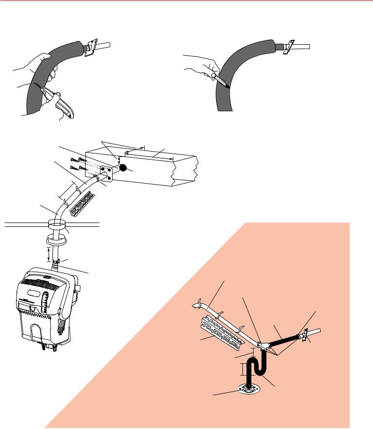
Cut a slit in the insulation half way around the hose.
not cut into the steam hose.
hose clamp into hook it onto the
.
|
3 in. minimum clearance from nozzle |
||
Nozzle at upward pitch. |
outlet to duct. |
|
24 in. open air downstream. |
|
|
||
Minimum upward |
|
|
|
pitch of 2 in. per ft. |
|
|
1-3/4 in. hole |
|
|
|
|
12 in. |
Clamp |
M28674 |
|
|
|
||
Avoid sharp kinks and |
On straight runs, use perforated angle |
prevent bends. |
iron. Otherwise, secure hose every 12 in. |
|
using provided hooks. |
|
Clearance hole for hose and insulation. |
|
Seal off unconditioned space with |
|
grommet (not provided) or caulk. |
6 in. of straight |
|
vertical rise. |
Clamp |
If hose slopes downhill…
Always install nozzle so the |
Downward slope can not be more than |
|||
3 ft below humidifier steam outlet. |
||||
outlet is pointed up. |
||||
|
|
|
||
Do not route the steam |
|
Provide a 212°F rated Tee at the |
||
hose through the hole in the |
|
lowest point. Do not use plastic Tee. |
||
mounting plate. |
|
|
Hose clamps at |
|
|
|
|
||
|
|
|
every connection. |
|
|
|
|
Minimum upward |
|
|
|
|
pitch of 2 in. per ft. |
|
On straight runs, use |
|
|
|
|
perforated angle iron. |
|
|
|
|
Otherwise, support |
|
|
Nozzle at |
|
hose every 12 in. using |
|
|||
provided hooks. |
|
|
upward pitch. |
|
|
Minimum 6 in. |
Clamps |
||
|
Minimum 2 in. |
|
||
|
|
|
Water in elbow. |
|
Always consult and follow local |
|
M28675 |
||
plumbing codes for drain pipe size and maximum temperature requirement.
69-2285EFS—03 |
24 |
TrueSTEAM Humidification System
Appendix B: Advanced Wiring
TrueSTEAM wired to a dedicated fan/blower.
TrueSTEAM nozzle must be injected |
1 |
|
|
|
|
|
GF |
|
|
|
|
|
|
|
|
|
||
|
|
|
|
|
|
|
|
|
|
|
|
|
|
|
|
|
||
into a dedicated duct box. Do not |
|
R |
24V |
|
|
OPTIONAL |
2 |
|
|
|
GENERAL PURPOSE |
|||||||
leave nozzle exposed. |
|
C |
24V |
|
|
|
|
|
|
SPST RELAY |
|
FAN / BLOWER |
||||||
|
|
|
AIR PROVING SWITCH |
|
|
|
||||||||||||
|
|
|
|
|
|
|
|
# R8222 |
|
|||||||||
|
|
|
|
|
|
|||||||||||||
|
|
|
|
|
|
|
|
C C |
|
|
|
|
|
|
|
|
MINIMUM 250 CFM |
|
• |
Required 4 in. clearance from |
|
HUM |
HUM |
|
|
|
|
|
|
|
|
|
RED |
|
120 VAC |
||
|
nozzle to any duct surface. |
|
HUM |
HUM |
|
R |
|
|
C |
|
|
|
|
|
|
|
||
|
|
|
|
|
|
|
|
|
|
|
|
|
|
|||||
• |
Required 24 in. open air space |
|
|
|
|
|
|
|
|
|
|
|
|
|
|
|||
|
|
|
|
|
20VA |
|
|
|
|
|
|
|
|
|
||||
|
|
|
|
|
|
|
|
|
|
|
|
|
|
|||||
|
downstream from nozzle. |
|
|
|
|
|
|
|
|
|
|
|
|
|
|
|||
|
|
|
|
|
|
TRANSFORMER |
BLACK |
|
|
|
|
|
||||||
|
|
|
|
|
|
|
# AT120 |
|
|
|
|
|
|
|
|
|
||
• |
Install fan/blower on upstream |
|
|
1 IN TRUEIAQ INSTALLER SETUP, SET ISU #25 TO 3. |
L1 120 VAC |
L2 |
||||||||||||
|
|
|
|
|
|
|
||||||||||||
|
end of duct box. |
|
|
2 IF AIR PROVING SWITCH IS USED, SET TRUESTEAM DIP 4 DOWN AND DIP 5 UP. |
||||||||||||||
|
|
|
|
|||||||||||||||
• |
Install a grille on downstream |
|
|
|
|
|
|
|
|
|
|
|
|
|
|
|
|
M28714 |
|
end of duct box. |
|
|
|
|
|
|
|
|
|
|
|
|
|
|
|
|
|
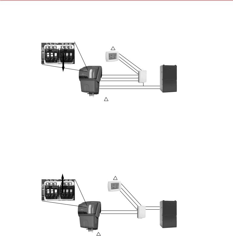
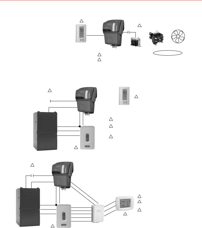
TrueSTEAM wired to a humidistat in a zoned application.
1 |
|
|
R |
24V |
|
TrueIAQ |
||
|
|
C |
24V |
|
||||
|
OPTIONAL |
|
|
|
||||
|
|
|
|
|
||||
|
|
|
HUM |
HUM |
|
|
||
AIR PROVING |
|
|
3 |
|||||
|
SWITCH |
C |
|
HUM |
HUM |
|||
|
|
|
|
|||||
|
|
|
|
|
|
|
|
|
|
|
|
GF |
|
|
|
|
|
|
|
|
|
|
|
|
||
C |
G |
|
|
|
|
|
|
|
|
|
|
|
|
|
|
|
|
|
R |
GT |
|
|
|
R |
RH |
G |
|
||
W |
W1/E |
|
Y |
Y1 |
|
1IF AIR PROVING SWITCH IS USED,
SET TRUESTEAM DIP 4 DOWN AND DIP 5 UP.
2CONNECT THE THERMOSTATS, DAMPERS, TRANFORMERS AND SENSOR WIRES AS SHOWN IN THE TRUEZONE HZ432 PANEL INSTRUCTIONS.
3IN TRUEIAQ INSTALLER SETUP, SET ISU #25 TO 3.
HZ432
PANEL
2 M28715
TrueSTEAM wired to a thermostat in a zoned application.
1
OPTIONAL
AIR PROVING
SWITCH C
GF
C G
HUM
HUM
R
GT
R |
RH |
G |
ZONE 1 |
|
R |
||
W |
W1/E |
|
|
|
C |
||
Y |
Y1 |
|
|
|
W1 |
||
|
|
|
|
|
|
|
Y1 |
|
HZ432 |
|
G |
|
PANEL |
|
|
|
2 |
|
|
|
|
|
VisionPRO IAQ |
HUM |
|
|
1 |
|
|
|
|
HUM |
|
1 |
2 |
|
|
|
|
R |
1 |
2 |
|
2 |
|
|
|
C |
3 |
3 |
|
3 |
|
||
|
|
|
W |
3 |
|
Y |
||
|
||
G |
|
IF AIR PROVING SWITCH IS USED, SET TRUESTEAM DIP 4 DOWN AND DIP 5 UP.
CONNECT THE THERMOSTATS, DAMPERS, TRANFORMERS AND SENSOR WIRES AS SHOWN IN THE TRUEZONE HZ432 PANEL INSTRUCTIONS.
IN VISIONPRO IAQ INSTALLER SETUP, SET ISU #0374 TO 3.
M28716
25 |
69-2285EFS—03 |
Installation Guide
Appendix B: Advanced Wiring
TrueSTEAM RedLINK connection in a zoned application.
1 |
|
|
|
|
|
|
|
|
|
A |
A |
|
|
ZONE 1 |
||||||||
|
|
|
|
|
|
|
|
|
B |
B |
|
|
||||||||||
OPTIONAL |
|
|
|
|
|
|
|
|
|
|||||||||||||
|
|
|
|
|
|
|
C |
C |
|
|
|
|
|
|
|
|||||||
AIR PROVING |
|
|
|
|
|
|
|
|
|
|
|
|
|
|
||||||||
|
|
|
|
|
|
|
D |
D |
|
|
3 |
|||||||||||
|
SWITCH |
C |
|
|
|
|
|
|
||||||||||||||
|
|
|
|
|
|
THM4000R |
||||||||||||||||
|
|
|
|
|
|
|
|
|
|
|
|
|
|
|
|
|
|
|
|
|||
|
|
|
|
|
GF |
|
|
|
|
|
|
|
|
|
|
|
|
|
||||
|
|
|
|
|
|
|
|
|
|
|
|
WIRELESS ADAPTER |
|
|
|
|
|
|||||
C |
G |
|
|
|
R |
|
GT |
|
|
|
|
(TrueSTEAM TO PRESTIGE) |
|
|
|
|
|
|||||
|
|
|
|
|
|
|
|
|
|
|
|
|
|
|
|
|||||||
|
|
|
|
|
|
|
|
|
|
|
|
|
|
|
|
|
||||||
|
|
|
|
|
|
|
|
|
|
|
|
|
|
|
|
|
|
|
|
|
|
|
|
|
|
|
R |
RH |
|
G |
|
|
|
|
|
|
|
|
R |
C |
Y |
W |
G |
||
|
|
|
|
|
|
|
|
|
R |
|
|
|
|
|
|
|
|
|||||
|
|
|
|
|
|
|
|
|
|
|
|
|
|
|
|
|
|
|||||
|
|
|
|
W |
W1/E |
|
|
|
|
|
|
C |
|
|
|
|
|
|
|
|
||
|
|
|
|
|
|
|
|
|
|
Y |
|
|
|
|
|
|
|
|
||||
|
|
|
|
Y |
Y1 |
|
|
|
|
|
|
|
|
|
|
|
|
|
|
|||
|
|
|
|
|
|
|
|
|
|
W |
|
|
|
|
|
|
|
|
||||
|
|
|
|
|
|
|
|
|
|
|
|
|
|
G |
|
|
|
|
|
|
|
|
|
|
|
|
|
|
|
|
|
|
|
|
|
|
A |
A |
|
|
|
ZONES |
|||
|
|
|
|
|
HZ432 |
|
|
|
|
|
|
B |
B |
|
|
|
||||||
|
|
|
|
|
|
|
|
|
|
|
C |
C |
|
WIRELESS |
2-4 |
|
||||||
|
|
|
|
|
|
|
|
|
|
|
|
|
|
|
|
|||||||
|
|
|
|
|
PANEL |
|
|
|
|
|
|
D |
D |
|
ADAPTER |
4 |
|
|||||
|
|
|
|
|
2 |
|
|
|
|
|
|
|
|
|
THM4000R |
|
||||||
|
|
|
|
|
|
|
|
|
|
|
|
|
|
|
|
|
|
|
||||
|
|
|
|
|
|
|
|
|
|
|
|
|
|
|
|
|
|
|
|
|||
|
|
|
|
|
|
|
|
|
|
|
|
|
|
|
WIRELESS ADAPTER |
|
|
|
|
|
||
|
|
|
|
|
|
|
|
|
|
(ZONES TO FOCUSPRO AND/OR PRESTIGE) |
||||||||||||
1 IF AIR PROVING SWITCH IS USED, SET TRUESTEAM DIP 4 DOWN AND DIP 5 UP.
2 CONNECT THE THERMOSTATS, DAMPERS, TRANFORMERS AND SENSOR WIRES AS SHOWN IN THE TRUEZONE HZ432 PANEL INSTRUCTIONS. 3 IN PRESTIGE INSTALLER SETUP, PROGRAM HUMIDITY CALLS TO “HUMIDIFY INDEPENDENT OF FAN.”
4 ONE TRUEZONE HZ432 PANEL WITH A REDLINK ADAPTER WILL WIRELESSLY COMMUNICATE WITH 3 ADDITIONAL ZONES WITH REDLINK THERMOSTATS.
M28717
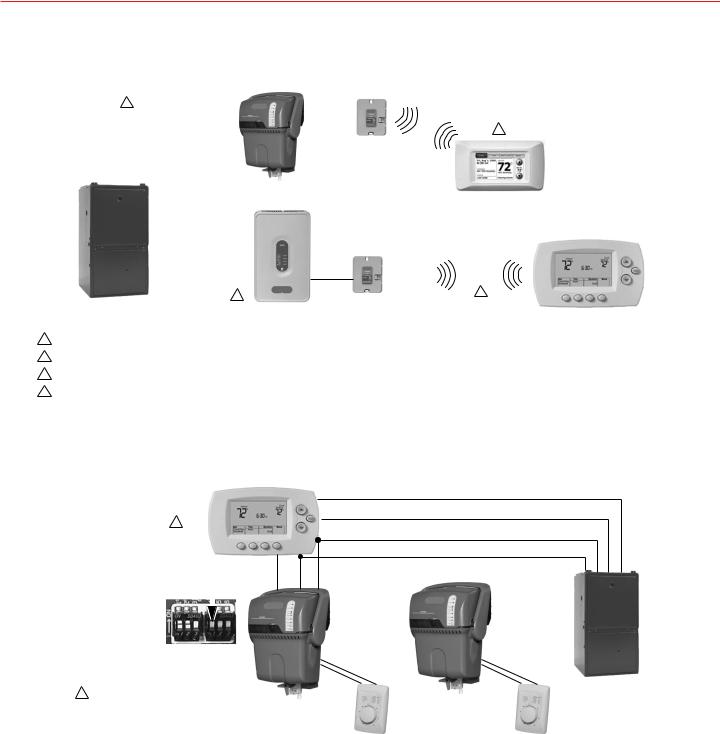
Wiring multiple TrueSTEAMs to one HVAC system.
CONVENTIONAL |
|
|
Y |
THERMOSTAT |
|
|
|
1 |
|
|
W |
|
|
|
|
|
|
|
C |
|
G |
R |
|
DIP 4 DOWN. |
|
|
|
BOTH TrueSTEAMS |
GT |
R |
C |
|
|
|
|
|
GF |
GT |
|
|
|
|
|
|
|
||
|
|
|
|
|
R |
R |
|
|
|
|
|
|
C |
C |
|
|
|
|
|
|
HUM |
|
|
|
|
|
HUM |
|
|
||
1 |
ENSURE THERMOSTAT ISOLATES Y FROM G. |
|
|
||||
|
ALL HONEYWELL PRESTIGE, VISIONPRO |
|
|
||||
AND FOCUSPRO THERMOSTATS DO THIS. |
SEPARATE |
|
HUMIDITY |
||
|
||
|
CONTROL |
Y
W
C
|
|
|
|
|
R |
|
|
GF |
G |
|
|
|
|
R |
R |
|
|
|
|
C |
C |
||
|
|
HUM |
|
|
|
HUM |
|
|
|
||
|
|
|
SEPARATE |
||
|
|
|
HUMIDITY |
||
|
|
|
CONTROL |
||
M28718
69-2285EFS—03 |
26 |
 Loading...