


Hr200b1005
APPLICATION
HR150, 200, 205; ER150, 200
Perfect Window™
Fresh Air Ventilation Systems
PRODUCT DATA
FEATURES
• Low voltage, high-speed override.
• Integral balancing dampers for quick installation.
• Provides ventilation that helps contractors meet
ASHRAE 62-89.
• 4-speed fan control.
• Automatic, economical built-in frost control available
for operation to design temperatures of -40°F (-40°C).
• HR150, HR200 and HR205 models have an easy-toclean aluminum cross-flow core.
• ER150 and ER200 models have an advanced enthalpy
heat and moisture recovery fixed core.
• Includes vibration isolation hardware and duct collars.
• Insulated cabinet made of rugged steel.
• Permanent (washable) prefilters.
• Quiet operation.
• Digital fan timer option on all models.
The HR150, HR200, and HR205 Perfect Window™ Fresh Air
Ventilation Systems provide proper levels of ventilation with
energy savings by transferring heat between the exhaust and
fresh air streams.
The ER150 and ER200 Perfect Window™ Fresh Air
Ventilation Systems provide proper levels of ventilation with
energy savings by transferring heat and moisture between the
exhaust and fresh air streams.
The ER150C and ER200C are specifically designed for
installations in unconditioned spaces such as attics and
garages.
Contents
Application/Features..........................................................1
Specifications/Ordering Information ..................................2
Planning the Installation ....................................................5
Installation .........................................................................8
Wiring ................................................................................9
Startup and Checkout/Service...........................................11
Troubleshooting.................................................................13
Parts List ...........................................................................15
® U.S. Registered Trademark
Copyright © 2004 Honeywell International Inc.
All Rights Reserved
68-0171-9

HR150, 200, 205; ER150, 200 PERFECT WINDOW™ FRESH AIR VENTILATION SYSTEMS
SPECIFICATIONS
IMPORTANT
The specifications given in this publication do not
include normal manufacturing tolerances. Therefore,
this unit might not exactly match the listed specifications. Also, this product is tested and calibrated
under closely controlled conditions, and some minor
differences in performance can be expected if those
conditions are changed.
TRADELINE® Models
TRADELINE models are selected and packaged to provide
ease of stocking, ease of handling and maximum replacement
value.
TRADELINE Models Available:
HR150, HR200, and HR205 Fresh Air Ventilation Systems:
Includes heat transfer core, prefilters, fan and blower
assembly and frost control.
HR150B: 150 cfm, aluminum core, manual control and
frost control.
HR200B: 200 cfm, aluminum cross flow core, manual
control and frost control.
HR205B: 200 cfm, aluminum cross flow core and frost
control (available in Canada only).
ER150B: 150 cfm, moisture transferring core, manual
control and frost control.
ER150C: 150 cfm, moisture transferring core, manual
control and without frost control.
ER200B: 200 cfm, moisture transferring core, manual
control and frost control.
ER200C: 200 cfm, moisture transferring core, manual
control and without frost control.
Color: White
Electrical Ratings:
Power Rating: 120 Vac, 60 Hz
Consumption:
Nominal Current (Amps)
HR150/
Mode
Minimum speed 0.7 0.8 0.07
Maximum speed 1.7 1.7 1.4
ER150
HR200/
ER200 HR205
Mounting:
Most models mount in conditioned space such as a
basement, utility room, hallway or closet. Can also be
mounted in conditioned attic space.
NOTE: ER150C and ER200C models can be installed in
unconditioned spaces such as attics and garages.
Approvals:
Home Ventilation Institute (HVI): Certified.
Canadian Standards Association: Approved.
ETL: Certified to UL1812.
Installed Weight:
HR150/HR200: 70 lb (32 kg).
HR205: 87 lb (40 kg).
ER150/ER200: 70 lb (32 kg).
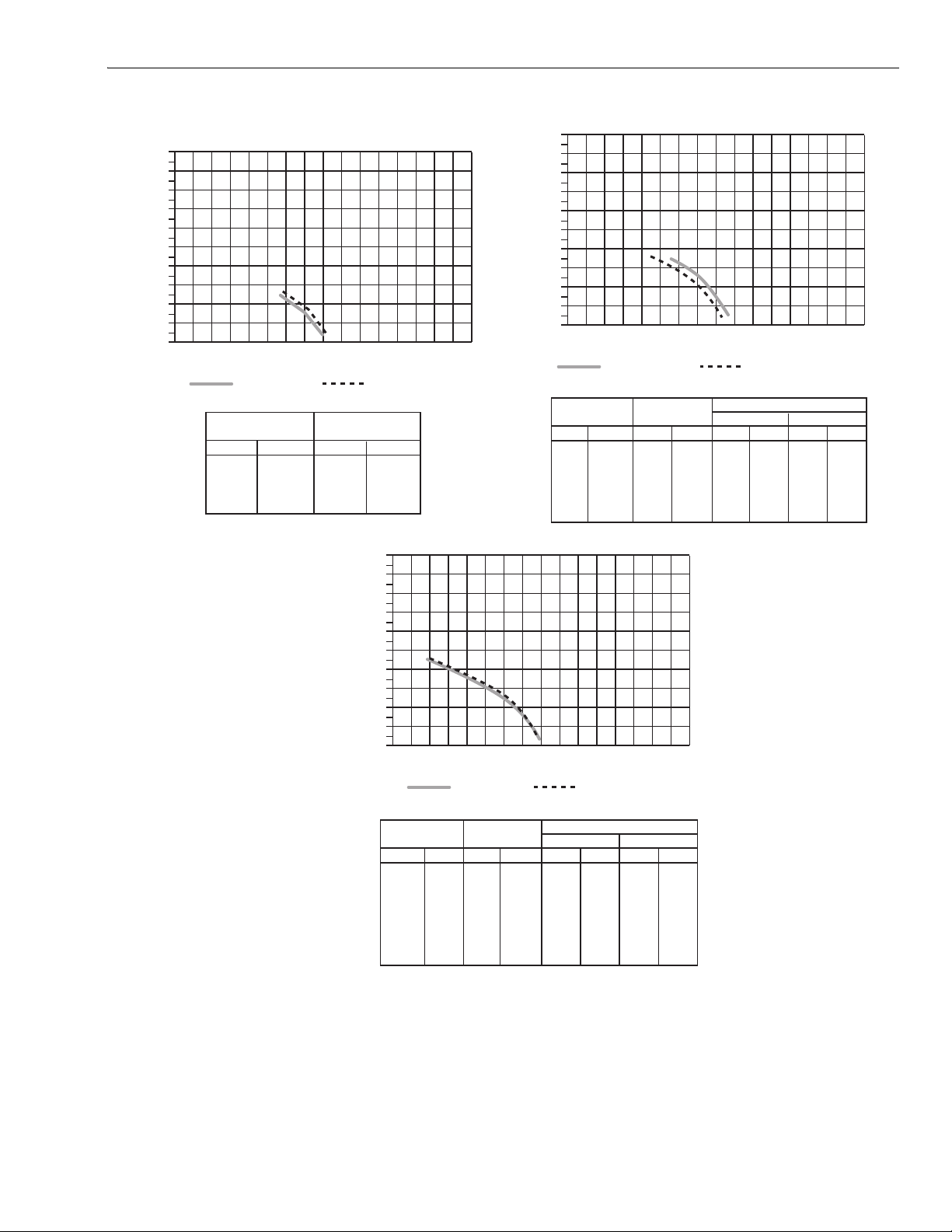
HVI Certifier Ventilation Performance: See Fig. 1.
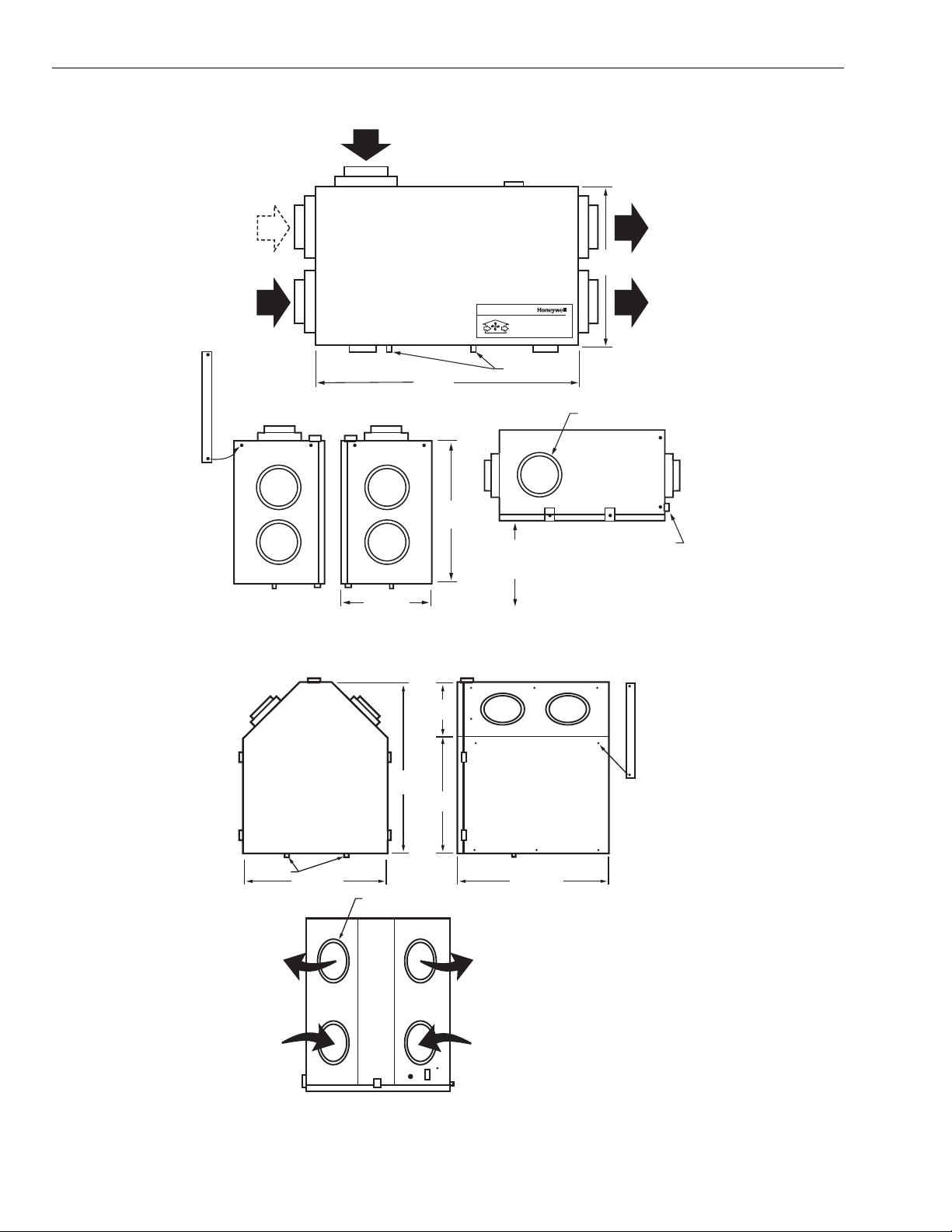
Dimensions: See Fig. 2 and 3.
Accessories:
See the HR Accessory Items Parts List that follows the
Troubleshooting Guide.
HR150, HR200, HR205
Maximum Temperature Recovery: 80%.
Sensible Efficiency (Performance per CAN/CSA-C439-88):
Low Speed at 32°F (0°C): 68%.
High Speed at 32°F (0°C): 62%.
Low Speed at -13°F (-25°C): 60%.
ER150, ER200
Sensible Efficiency (Performance per CAN/CSA-C439-88):
110 cfm at 61°F (16°C): 79%.
Moisture Transfer Ratio: 26%.
ORDERING INFORMATION
When purchasing replacement and modernization products from your TRADELINE® wholesaler or distributor, refer to the
TRADELINE® Catalog or price sheets for complete ordering number.
If you have additional questions, need further information, or would like to comment on our products or services, please write or
phone:
1. Your local Honeywell Automation and Control Products Sales Office (check white pages of your phone directory).
2. Honeywell Customer Care
1885 Douglas Drive North
Minneapolis, Minnesota 55422-4386
In Canada—Honeywell Limited/Honeywell Limitée, 35 Dynamic Drive, Scarborough, Ontario M1V 4Z9.
International Sales and Service Offices in all principal cities of the world. Manufacturing in Australia, Canada, Finland, France,
Germany, Japan, Mexico, Netherlands, Spain, Taiwan, United Kingdom, U.S.A.
68-0171-9 2
2
A
A
1.8
1.6
1.4
1.2
1
0.8
0.6
in. wg (Pa = n x 248.8)
0.4
0.2
0
0
50 150100 200 250 300 350
HR150/ER150 VENTILATION PERFORMANCE
EXT STATIC
(Pa) (in. wg) (L/s) (cfm)
100
125
HR150, 200, 205; ER150, 200 PERFECT WINDOW™ FRESH AIR VENTILATION SYSTEMS
cfm (L/s = n x 0.4719)
NET SUPPLY NET EXHAUST
NET SUPPLY
PRESSURE
25
50
75
.1
.2
.3
.4
.5
AIR FLOW
91
177
89
164
84
156
78
143
69
123
2
1.8
1.6
1.4
1.2
1
0.8
0.6
in. wg (Pa = n x 248.8)
0.4
0.2
0
0
EXT. STATIC
(Pa) (in. wg) (L/s) (cfm) (L/s) (cfm) (L/s) (cfm)
100
125
150
175
200
225
PRESSURE
25
50
75
2
1.8
1.6
1.4
1.2
1
0.8
0.6
in. wg (Pa = n x 248.8)
0.4
0.2
0
0
50 150100 200 250 300 350
400
GROSS SUPPLY GROSS EXHAUST
HR200/ER200 VENTILATION PERFORMANCE (HVI)
EXT STATIC
PRESSURE
(Pa) (in. wg) (L/s) (cfm) (L/s) (cfm) (L/s) (cfm)
25
50
75
100
125
M6561
50 150100 200 250 300 350
cfm (L/s = n x 0.4719)
NET SUPPLY NET EXHAUST
150
175
.1
.2
.3
.4
.5
.6
.7
NET SUPPLY
AIR FLOW
104
97
91
87
80
73
64
HR205 VENTILATION PERFORMANCE (HVI)
.1
.2
.3
.4
.5
.6
.7
.8
.9
NET SUPPLY
AIR FLOW
93
196
89
188
84
178
78
165
71
149
62
131
51
109
37
79
23
48
GROSS AIR FLOW
SUPPLY
94
199
90
190
85
181
79
167
71
151
63
133
52
110
38
80
23
49
EXHAUST
93
88
83
77
73
64
51
41
22
cfm (L/s = n x 0.4719)
GROSS AIR FLOW
SUPPLY
214
102
206
98
193
93
184
88
170
81
155
74
137
65
400
197
186
176
153
154
134
108
86
47
M6563
216
208
197
186
172
157
138
EXHAUST
97
93
88
82
75
67
54
206
197
186
174
159
142
114
M6562A
400
Fig. 1. Ventilation Performance.
3 68-0171-9
HR150, 200, 205; ER150, 200 PERFECT WINDOW™ FRESH AIR VENTILATION SYSTEMS
FRESH AIR
FROM OUTSIDE
DEFROST
PORT
STALE AIR
FROM HOUSE
Fresh Air Ventilation System
Système de ventilation à air frais
DRAIN SPOUTS
SERVICE
CLEARANCE
25
(635)
WEIGHT: 70 lb (32 kg)
SHIPPING WEIGHT: 72 lb (33 kg)
MOUNTING
STRAP (4)
14-3/4 (375)
33-5/8 (854)
(483)
19
Fig. 2. HR150/ER150 and HR200/ER200 dimensions in in. (mm).
STALE AIR
TO OUTSIDE
19
(483)
FRESH AIR
TO HOUSE
ALL DUCT CONNECTIONS
ARE 6 (150).
HR
CONTROLS
M6546B
DRAIN
SPOUTS
STALE AIR
EXHAUST
SUPPLY OF
FRESH AIR
7-1/2
(191)
25-1/2
(648)
18
(457)
26-1/2 (673)22-1/2 (572)
ALL DUCT CONNECTIONS
ARE 6 (150).
FRESH AIR
SUPPLY TO
BUILDING
STALE AIR
RETURN FROM
BUILDING
WEIGHT: 87 lb. (40 kg)
SHIPPING WEIGHT: 89 lb. (41 kg)
Fig. 3. HR205 dimensions in in. (mm).
MOUNTING
STRAP (4)
M6547A
68-0171-9 4
HR150, 200, 205; ER150, 200 PERFECT WINDOW™ FRESH AIR VENTILATION SYSTEMS
A
PLANNING THE INSTALLATION
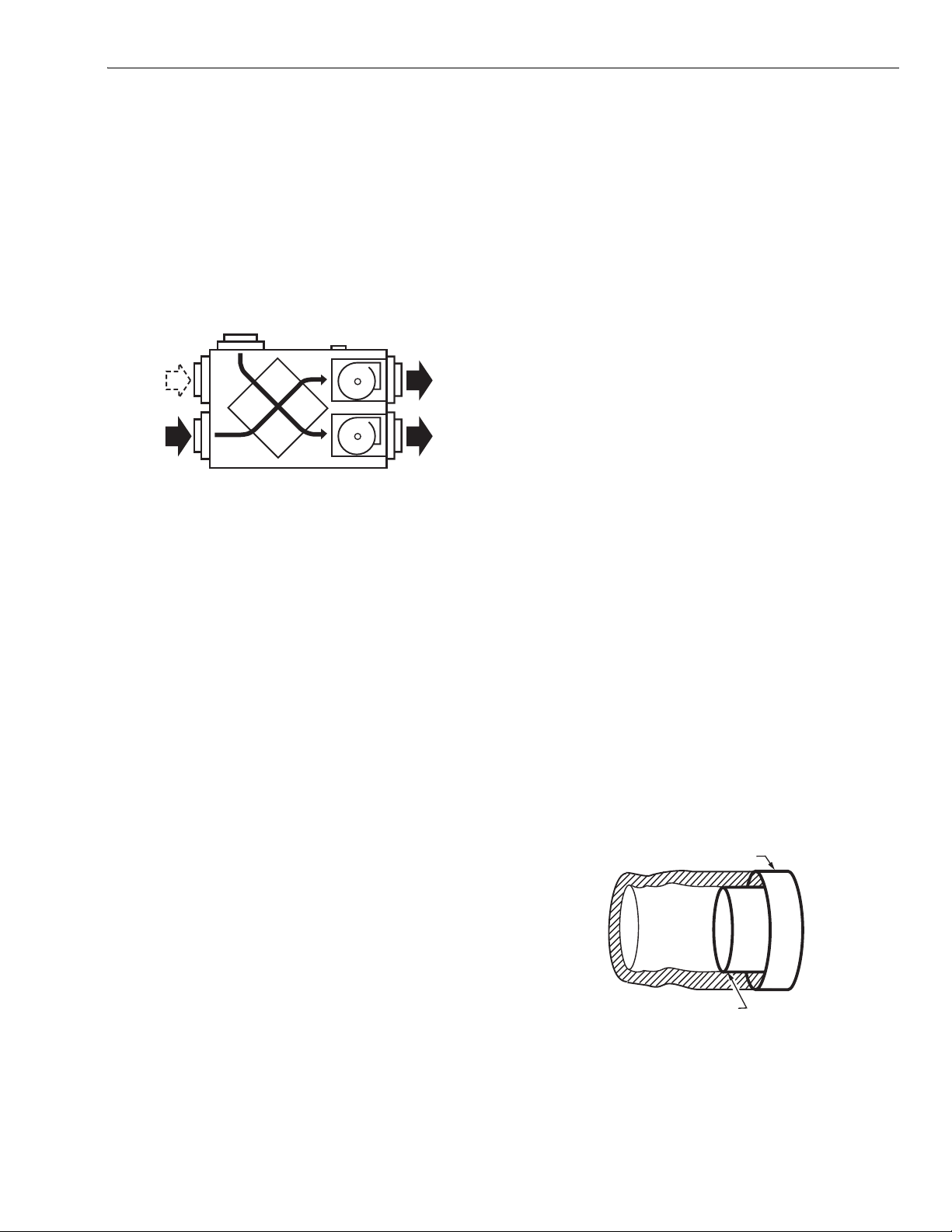
Application
The Fresh Air Ventilation System is designed to supply fresh
air and exhaust stale air. The system draws fresh outdoor air
through the ventilator for distribution throughout the house.
Stale air is exhausted through the ventilator and to the
outdoors. Heat is transferred from one airstream to the other
as the air passes through the opposite sides of the heat
transfer core. See Fig. 4.
FRESH
AIR IN
DEFROST
PORT
STALE
IR FROM
HOUSE
Fig. 4. Duct connections and airflow.
Sizing
There are several methods that can provide satisfactory
results for sizing a ventilator to provide adequate ventilation
for a home. The ASHRAE Standard 62-1989 Ventilation for
Acceptable Indoor Air Quality suggests the following:
— .35 air changes per hour (ach) but not less than 15 cfm per
person for living areas = house size (sq ft) • ceiling height
(ft) / 60 (min) •.35 (ach)
Example:
= 2000 sq ft • 8 ft / 60 min •.35 ach = 93 cfm
— 50 cfm intermittent or 20 cfm continuous capacity for
bathrooms
Example:
50 cfm intermittent • 3 bathrooms = 150 cfm
20 cfm continuous • 3 bathrooms = 60 cfm
— 100 cfm intermittent or 25 cfm continuous capacity for
kitchens
STALE
AIR TO
OUTSIDE
FRESH
AIR TO
HOUSE
M6553B
Option 2: Fresh Air Ventilation System provides continuous
93 cfm fresh air supply, 150 cfm intermittent exhaust capacity
for bathrooms and continuous 50 cfm kitchen ventilation.
Supply air flow required = 93 cfm
Exhaust air flow required = 200 cfm
Honeywell HR200/ER200 have the exhaust capacity required
to meet the ventilation needs of this application. See Fig. 1.
Mounting Position and Location
The HR150/ER150, HR200/ER200 and HR205 can be
suspended from exposed ceiling joists, ceiling surface or floor
mounted. (Level ventilator so drains function correctly.)
NOTE: ER150C and ER200C are specifically designed for
installations in unconditioned spaces such as attics
and garages. (These units are not equipped with
drain kits.)
• Locate fresh air intake 6 ft (2m) or more from stale air
exhaust to prevent exhaust air from re-entering.
• Locate ventilator where length of ducting required is
minimal.
Install HR150/ER150, HR200/ER200 and HR205 in a
conditioned space using these guidelines:
• Pipe drain line (ER150C and ER300C do not have drain
kits) from the ventilator to a drain.
• Use an existing electrical outlet with appropriate current
rating (or install one) close to ventilator power cord.
• Allow space for drain line by placing the ventilator at least
10 in. (254 mm) off the floor.
• For access and removal of ventilator core, allow at least
25 in. (635 mm) of open space in front of unit.
Ducting
Ducting between the ventilator and the outdoors must be
insulated and have a continuous air vapor barrier. See Fig. 5.
IMPORTANT
All ducting to the outdoors must be terminated above
anticipated snow lines and be fitted with a weather
cap that incorporates bird screening.
SEAL OUTER LINING OF FLEX
DUCT TO OUTER COLLAR
Example:
100 cfm intermittent • 1 kitchen = 100 cfm
25 cfm continuous • 1 kitchen = 25 cfm
INSULATED
FLEX DUCT
COLLAR ON
VENTILATOR
Option 1: Fresh Air Ventilation System provides continuous
fresh air supply of 93 cfm, and intermittent capacity for
bathrooms of 150 cfm. A separate 100 cfm exhaust fan is
used for the range hood.
Supply air flow required = 93 cfm
Exhaust air flow required = 150 cfm
Any Honeywell ventilation unit provides suitable ventilation
capacity. See Fig. 1.
Design and installation of ductwork must be according to
standard HVAC practice to deliver required quantities of fresh
air to temperature-controlled space and exhaust equivalent
quantities of room air to the outside.
5 68-0171-9
SEAL INTERIOR LINING OF
FLEX DUCT TO INSIDE COLLAR
Fig. 5. Sealing insulated duct terminations.
M6557
HR150, 200, 205; ER150, 200 PERFECT WINDOW™ FRESH AIR VENTILATION SYSTEMS
A
Keep intake and exhaust duct runs as short as possible with
few bends or elbows.
• Keep duct sizes as large as possible throughout the
installation.
• Use a 6 in. diameter round duct for all connections to and
from the ventilator.
• Separate outside intake and exhaust vents by at least
6 ft (2m).
NOTES:
— Do not locate the fresh air vent where it blows
directly onto occupants or the thermostat.
— Do not locate the fresh air intake close to known
sources of pollutants such as automobile exhaust,
a dryer vent or chimney smoke.
• Ducting the supply outlet and/or the exhaust inlet of the
ventilator to the return air plenum of the air handler is an
excellent way to distribute fresh air and exhaust stale air
from all parts of the house, while reducing installation
OUTDOORS
costs. When choosing this method, balance the ventilator
when the air handler is running and interlock the ventilator
so that it can run only when the air handler runs. See
Fig. 6. An alternate method is to balance the ventilator
when the air handler is not running and let the ventilator
run whether the air handler is running or not, see Fig. 7. An
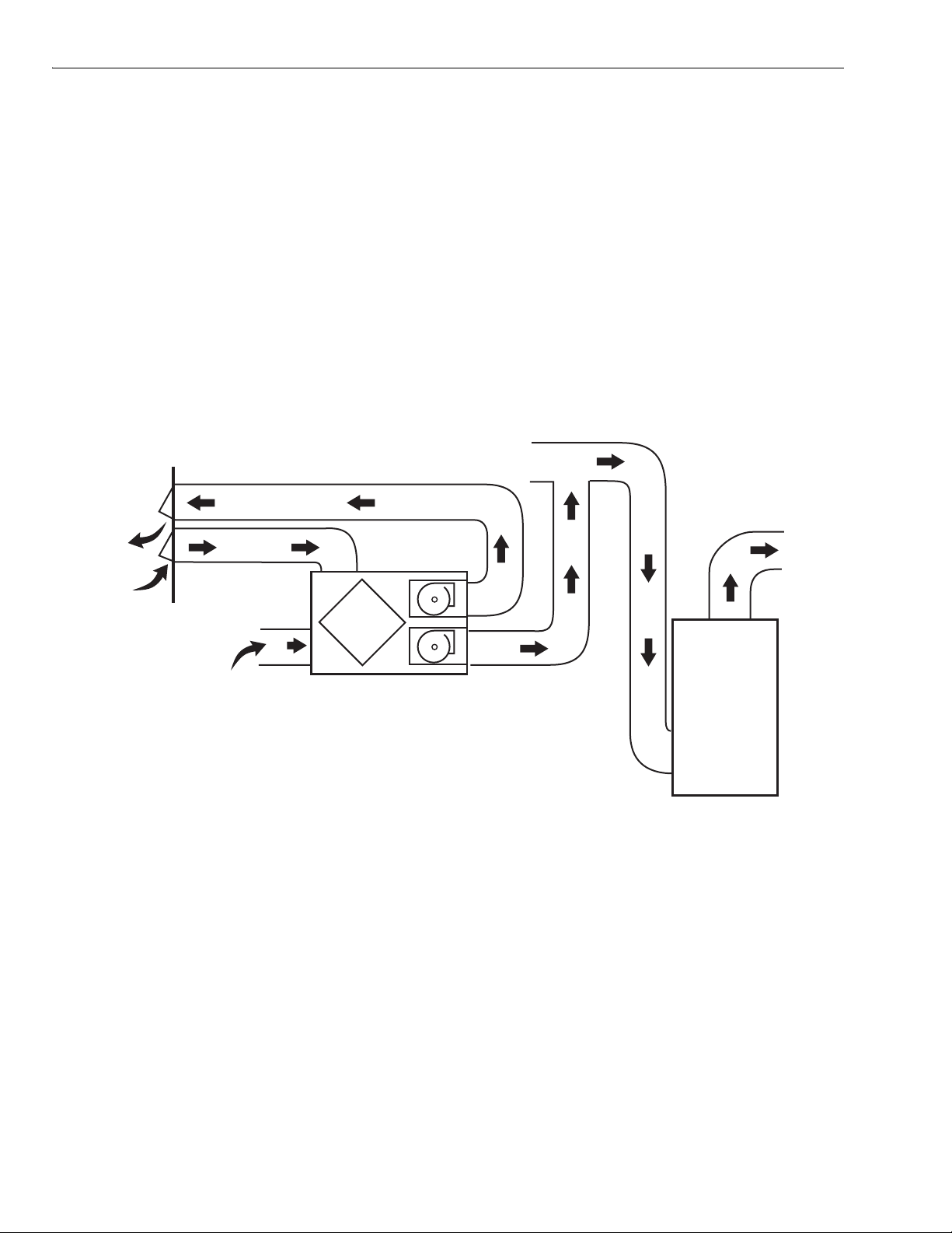
independent installation is shown in Fig. 8.
NOTE: When the home is occupied, continuous operation of
the ventilator is recommended. When the furnace air
handler operates, fresh air is distributed through the
heating/air conditioning supply registers. When the
air handler is off, fresh air is delivered through both
supplies and returns.
• An electrical interlock or an automatically powered damper
must be used to prevent unwanted entry of outside air if the
ventilator is turned off while the furnace air handler
continues to operate.
RETURN
AIR
COLD AIR
RETURN
EXHAUST AIR FROM
VARIOUS PARTS OF
HOME (BATHROOMS
IF REQUIRED; KITCHENS
IF REQUIRED; ROOMS
WITHOUT OPERABLE WINDOWS,
ND POTENTIALLY BASEMENTS).
NOTES:
FURNACE BLOWER NEED NOT OPERATE TO PROVIDE GOOD AIR DISTRIBUTION/QUALITY WITH THIS SYSTEM.
1.
IF FURNACE BLOWER OPERATION IS REQUIRED TO HELP DISTRIBUTE SUPPLY AIR: RUN CONTINUOUSLY
2.
OR INTERLINK ELECTRICALLY (LOW VOLTAGE) USING OPTIONAL 32003248-001 BLOWER INTERFACE KIT.
NO SEPARATION REQUIREMENTS ARE NECESSARY BETWEEN DIRECT CONNECTION POINT AND FURNACE.
3.
4.
WEATHER-HOOD ARRANGEMENT IS FOR DRAWING ONLY. 6 FT (2m) MINIMUM SEPARATION REQUIRED,
18 IN. (0.46m) ABOVE GRADE MINIMUM.
Fig. 6. Direct connection of supply air stream to furnace cold air return for HRV/ERV.
FORCED AIR
FURNACE
COMBUSTION
OR ELECTRIC
M6549C
68-0171-9 6
 Loading...