

Page 1
Operating Instructions
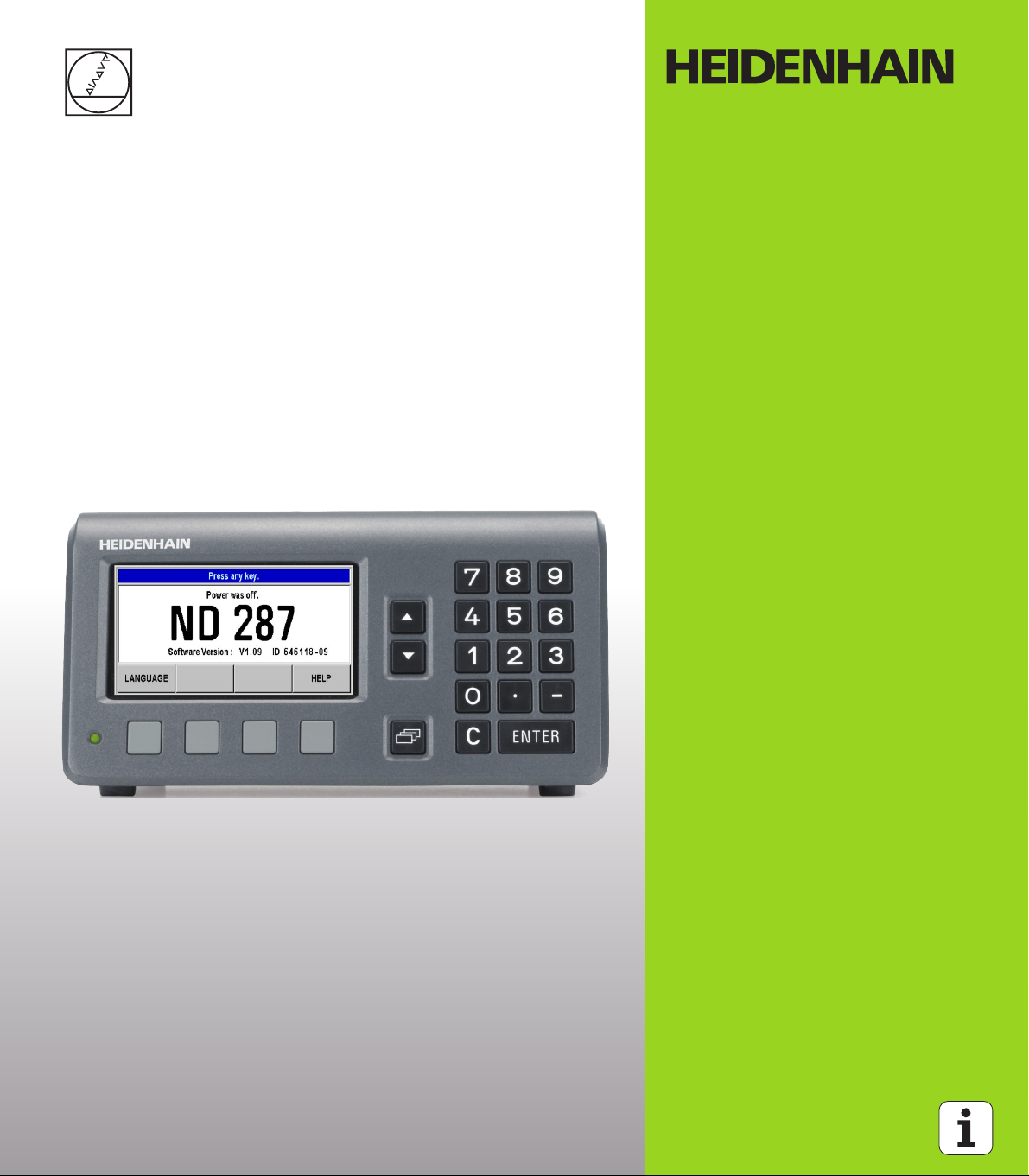
ND 287
English (en)
11/2013
Page 2
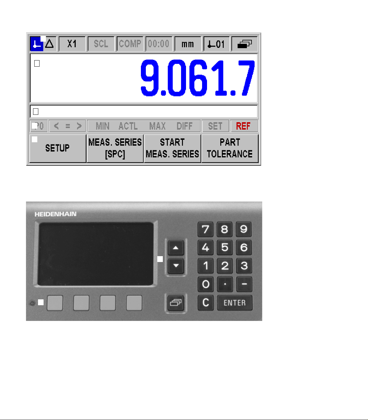
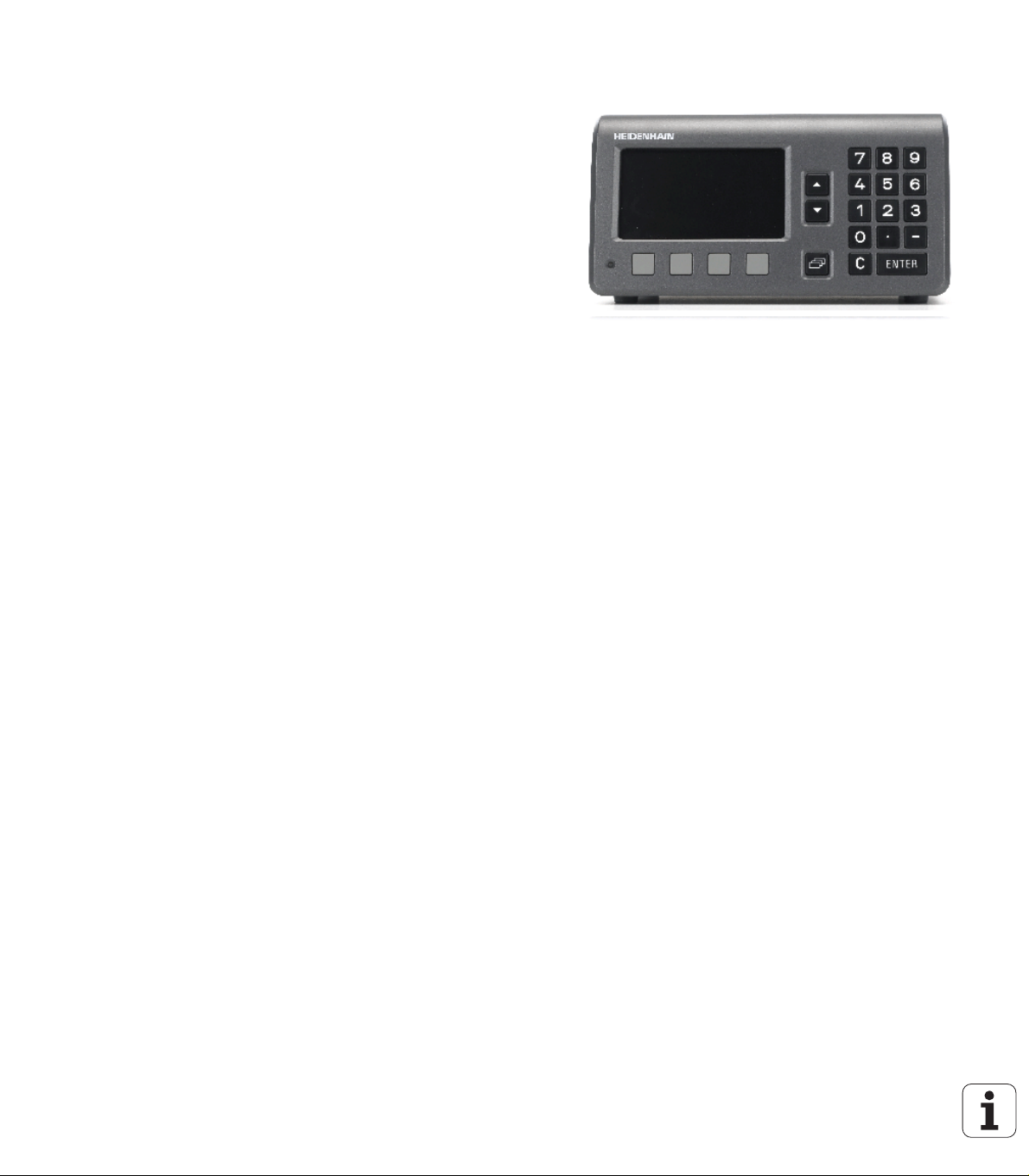
ND 287 screen
12345
7
6
ND 287 front panel
Page 3
Controls and displays
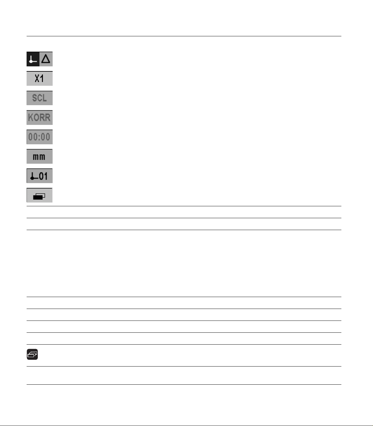
1 Status bar
Current operating mode: Actual Value, Distance-To-Go
Current display mode for input X1, X2 or coupled axes X1:X2
SCL shown in black: Scaling factor is active
COMP shown in black: Error compensation or axis-error compensation is active for the currently displayed axis
or coupled axes.
Elapsed time of running stopwatch: If the stopwatch is stopped, the box appears dimmed.
mm, inch, DEG, DMS or rad: Currently active unit of measure
Currently active datum: The ND 287 allows you to work with two different datums.
Indicates the soft-key page (soft-key row) you are currently on.
2 Position display: Current position value (length or angle), or other measured value
3 Message line for displaying information, errors or warnings
4 Status display:
<• / = / >: The first three symbols become effective when tolerance checking and sorting mode is activated.
MIN, ACTL or MAX and DIFF: Minimum, current or maximum measured value of a series of measurements,
or difference between minimum and maximum measured value.
SET: If you enter a new value during datum setting, the SET symbol will start flashing.
REF: The REF symbol is flashing until the reference mark evaluation for the displayed axis has been
completed (if an incremental encoder is connected).
P0-P9: Selected part is displayed for the sorting and tolerance checking mode.
5 and 6 Soft keys and soft-key buttons for executing functions
1,2,3,4... Numeric input keys
ENTER Use the ENTER key to confirm your entry or to return to the previous screen.
C Use the C key to clear an entry, acknowledge an error message or return to the previous screen.
The NAVIGATION key moves through the soft-key pages (soft-key rows).
7 Use the UP or DOWN arrow key to move between fields within a form or menu items (parameters) within a
menu.
Page 4
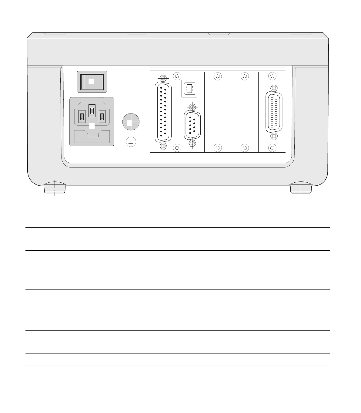
ND 287 rear panel
X1
X2
X26(X27)
X32/X31
X41
123
Connections
1 Power switch
2 Power connection with fuse
3 Ground (protective earthing)
X1 Encoder module for connecting a HEIDENHAIN encoder with 11 µApp, 1 Vpp or EnDat interface (purely
serial)
Option: Analog module for connecting an analog sensor
X2 Optional:
Encoder module for connecting a HEIDENHAIN encoder with 11 µApp, 1 Vpp
for a second axis or
Analog module for connecting an analog sensor, primarily a temperature sensor for axis-error
compensation
X26 (X27) Option: Ethernet module (100baseT) for network connection via TCP/IP protocol
X32/X31 Two serial ports for data transfer: RS-232-C/V.24 (X31) and USB Type B (UART, X32)
X41 Switching inputs and outputs at D-sub connection
or EnDat 2.1/2.2 interface
Page 5
Introduction
Software version
The software version is shown on the power-up screen of the ND 287.
This manual describes the functions that are available in
the ND 287 and the installation of the units.
Symbols within notes
Every note is marked with a symbol on the left indicating to the
operator the type and/or potential severity of the note.
General information
e. g. on the behavior of the ND 287.
Refer to accompanying documents
e.g. when a special tool is required for a function.
Danger to the operator, workpiece or internal
components
e.g. danger of collision
Introduction
Electrical hazard
e. g. danger of electrical shock when opening a housing.
The ND 287 must be prepared by a qualified and
authorized technician to perform this function.
Fonts
The chart below shows how the different variables (soft keys, hard
keys, forms and form fields) are represented within the text of this
manual:
Soft keys – SETUP soft key
Hard keys – ENTER hard key
Menus and forms – UNITS OF MEASURE form
Parameters and input fields – ANGULAR field
Data in fields - ON, OFF
ND 287 5
Page 6

Page 7

I Working with the ND 287 position display unit ..... 13
I – 1 ND 287 position display unit ..... 14
I – 2 Fundamentals of positioning ..... 16
Datums ..... 16
Actual position, nominal position and distance-to-go ..... 17
Absolute workpiece positions ..... 18
Incremental workpiece positions ..... 18
Incremental position encoders ..... 19
Absolute position encoders ..... 19
Reference marks ..... 20
I – 3 Basic functions of the ND 287 ..... 21
ND 287 power-up ..... 21
Reference mark evaluation ..... 22
Working without reference mark evaluation ..... 22
ND 287 shutdown ..... 22
Standard screen layout ..... 23
Soft-key functions on the standard screen ..... 25
Axis display mode ..... 27
Data input ..... 27
Integrated help system ..... 28
Data input forms ..... 29
Instruction box messages ..... 29
Error messages ..... 29
I – 4 Job Setup ..... 30
Operating modes ..... 30
Datum setting ..... 31
Setting the display value for one axis or for two axes in the X1 or X2 display mode ..... 31
Setting the display value for two axes in display mode X1:X2 (applies to X1+X2, X1-X2, f(X1,X2)) ..... 32
Calling the JOB SETUP menu ..... 33
Unit of measure ..... 34
Scaling factor ..... 35
Value for datum point ..... 36
Stopwatch ..... 36
Console adjustment ..... 37
Language ..... 37
Switching signals ..... 38
Measured-value output ..... 39
Function of external inputs ..... 40
Compensation using a reference part ..... 41
ND 287 7
Page 8

I – 5 Series of measurements and statistical process control ..... 42
Functions ..... 42
Switching between series of measurements and SPC mode ..... 42
Calling the SERIES OF MEASUREMENTS menu ..... 43
Analysis of series of measurements ..... 43
Setting up a series of measurements ..... 44
Defining the display for a series of measurements ..... 46
Setting the position or speed display ..... 47
Defining the record mode ..... 47
Starting and stopping a series of measurements ..... 48
Calling the SPC menu ..... 49
SPC analysis ..... 49
Setting up SPC ..... 52
Samples ..... 52
Tolerances ..... 53
Control limits ..... 54
Statistical distribution ..... 55
Measured value recording ..... 55
Deleting SPC statistics ..... 55
Starting and stopping SPC ..... 56
I – 6 Sorting and tolerance checking ..... 58
Sorting function ..... 58
Defining the sorting parameters and part tolerances ..... 59
I – 7 Error messages ..... 60
Overview ..... 60
8
Page 9

II Installation, specifications ..... 63
II – 1 Installation and electrical connection ..... 64
Items supplied ..... 64
Optional accessories ..... 64
Mounting ..... 65
Environmental conditions ..... 65
Mounting location ..... 65
ND 287 – Mounting and installation ..... 65
Electromagnetic compatibility/
CE compliance ..... 66
Electrical connection ..... 67
Electrical requirements ..... 67
Wiring the power connector ..... 67
Grounding ..... 67
Preventative maintenance or repair ..... 68
Connecting the encoders ..... 68
D-sub connection X1/X2 (15-pin, female) for the following input signals ..... 68
Optional: Analog module with ±10 V interface at input X1 or X2 for connecting an analog sensor ..... 69
II – 2 Installation Setup ..... 70
INSTALLATION SETUP menu ..... 70
Setting up the encoder ..... 71
Incremental linear encoder ..... 72
Incremental rotary encoder ..... 73
Absolute encoder ..... 74
Using an absolute multiturn rotary encoder as a linear encoder ..... 74
Analog sensor with ±10 V interface, preferably a temperature sensor ..... 75
Configuring the display ..... 76
Linear encoder ..... 76
Rotary encoder ..... 76
Analog sensor for compensation ..... 76
Counter settings ..... 77
Setting the display modes of the axes ..... 78
Formula for coupled position ..... 78
Error compensation ..... 79
Linear error compensation (not for rotary encoders) ..... 80
Non-linear error compensation ..... 81
Setting up the serial port ..... 85
Setting up the data interface ..... 85
Diagnostics ..... 87
Keypad test ..... 87
Display test ..... 87
Encoder test ..... 88
Power supply ..... 90
Switching inputs test ..... 91
Switching outputs test ..... 92
ND 287 9
Page 10

II – 3 Switching inputs and outputs ..... 93
Switching inputs at D-sub connection X41 ..... 93
Input signals ..... 94
Signal level of inputs ..... 94
Ignoring the reference mark signals ..... 94
Switching outputs at D-sub connection X41 ..... 95
Output signals ..... 95
Signal level of outputs ..... 95
Trigger limits ..... 96
Sorting limits ..... 97
Trigger signal for error ..... 97
Zero crossover ..... 97
II – 4 Encoder parameters ..... 98
Table values ..... 98
HEIDENHAIN linear encoders ..... 98
HEIDENHAIN rotary encoders ..... 99
II – 5 Data interface ..... 100
Data communication ..... 100
Serial data transfer with the Import or Export function ..... 101
Data transfer from the ND 287 to a printer ..... 101
Data transfer from the ND 287 to a PC ..... 101
Importing data into the ND 287 from a PC ..... 102
Data format ..... 102
Control characters ..... 102
Software update (firmware update) installation ..... 103
Wiring the connecting cable ..... 104
USB Type B (UART), socket as per IEC 61076-3-108 ..... 105
External operation via RS-232-C/V.24 or USB interface ..... 106
Key commands ..... 106
Description of key commands ..... 107
Key is pressed (TXXXX commands) ..... 108
Output of screen contents (AXXXX commands) ..... 108
Execute function (FXXXX commands) ..... 112
Execute special function (SXXXX commands) ..... 112
10
Page 11

II – 6 Measured value output ..... 113
Alternatives for starting measured value output ..... 113
Measured value output after a trigger signal ..... 113
Propagation times ..... 113
Duration of measured value transfer ..... 113
Measured-value output via the serial data interface X31 or X32 ..... 114
Propagation times ..... 114
Duration of measured value transfer ..... 115
Example: Data sequence during measured-value output ..... 115
II – 7 Input and output of parameter list and error compensation table ..... 116
Text file ..... 116
Output format of the parameter list ..... 117
First line ..... 117
Second line ..... 117
Subsequent lines for the individual parameters ..... 117
Last line ..... 117
Examples of parameter lists ..... 118
ND 287 with rotary encoder connected to input X1 ..... 118
ND 287 with two rotary encoders connected to inputs X1 and X2 (optional) ..... 123
Output format of the error compensation table ..... 128
First line ..... 128
Second line ..... 128
Third line ..... 128
Fourth line (only if second axis input is available, optional) ..... 129
Fifth line ..... 129
Sixth line ..... 129
Seventh line ..... 130
Subsequent lines for further compensation values ..... 130
Last line ..... 130
Examples of error compensation tables ..... 131
ND 287 with linear encoder connected to input X1 ..... 131
ND 287 with two linear encoders connected to inputs X1 and X2 (optional) ..... 133
ND 287 with rotary encoder connected to input X1 ..... 135
II – 8 Specifications for ..... 137
ND 287 ..... 137
II – 9 Dimensions ..... 140
ND 287 ..... 140
II – 10 Accessories ..... 141
ID numbers for accessories ..... 141
Mounting the input assemblies ..... 142
Mounting base for installation in 19-inch electrical cabinet ..... 143
ND 287 11
Page 12

12
Page 13

Working with the ND 287 position display unit
ND 287 13
Page 14
I – 1 ND 287 position display unit
The ND 287 position display unit from HEIDENHAIN is designed for
measuring devices, adjustment and testing equipment, automated
tasks, as well as infeed and positioning tasks with up to two axes that
can be moved manually.
Linear/angular/rotary encoders, length gauges or analog sensors can
be connected to the ND 287. The ND 287 features two slots for the
connection of modular input assemblies:
An encoder module for connecting an incremental photoelectrical
HEIDENHAIN encoder with sinusoidal 11 µApp, 1 Vpp signals or an
absolute HEIDENHAIN encoder with bidirectional EnDat interface
(purely serial) is a standard item supplied with the position display
unit.
Optional modules that can be easily adapted to the ND's
requirements:
Second encoder module for connecting a HEIDENHAIN encoder
with 11 µApp, 1 Vpp or EnDat interface (purely serial) or
Analog module for connecting an analog sensor with ±10 V
interface, primarily a temperature sensor for axis-error
I – 1 ND 287 position display unit
compensation
Sorting and tolerance checking function with capacity for saving
the tolerances of 10 parts
The following functions are available on the ND 287:
Multilingual user guidance: Language can be selected by the user
REF reference-mark evaluation for distance-coded or single
reference marks
Display of position value (length or angle), traversing speed for
series of measurements or other measured values from analog
sensors
Distance-To-Go or Actual Value operating mode
Two datums
Scaling factor
Stopwatch
Reset or Preset function, also through external signal
Linear or non-linear error compensation for axis-error
compensation
Switching inputs and outputs
Fig. I.1 ND 287
14 I Working with the ND 287 position display unit
Page 15

Series of measurements:
Sorting measured values and finding the Minimum, Maximum,
Sum, Difference or a definable coupled position value.
Displaying the sorting results in order to intervene, if necessary.
Memory capacity for series of measurements: Up to 10 000
measured values per axis.
Analysis of series of measurements: Arithmetical mean value,
standard deviation, graphical representation of all measured
values with minimum, maximum and mean value of the series of
measurements.
Measured-value acquisition by external signal or selectable
sampling interval, or by pressing the ENTER key.
Statistical Process Control (SPC):
Calculation of arithmetical mean value, standard deviation and
range. Displaying graphs or histograms with symmetrical or
asymmetrical density function.
Process capability indices c
mean value, standard deviation and range.
Measured-value acquisition by external signal or by pressing the
ENTER key.
FIFO memory capacity: Up to 1000 measured values.
There are two serial ports for transmitting measured values,
compensation values or configuration parameters to a PC or printer:
The data can be transferred via the RS 232-C/V.24 or the USB Type
B (UART) interface. It is also possible to download software via the
serial interface.
Diagnostic functions for testing the encoder, the keyboard, the
screen, the supply voltage and the switching inputs/outputs.
On the ND 287, one measured value can be displayed in large
characters on the screen at any one time. If two encoders are
connected to the ND, you can switch the display from the position
value supplied by the first encoder to the position value supplied by
the second encoder, or to a defined coupled position value.
The integrated help system provides information and assistance in
any situation.
and cpk, quality control charts for
p
I – 1 ND 287 position display unit
ND 287 15
Page 16
I – 2 Fundamentals of positioning
?
Z
?
?
?
?
0
Z
10
20
30
40
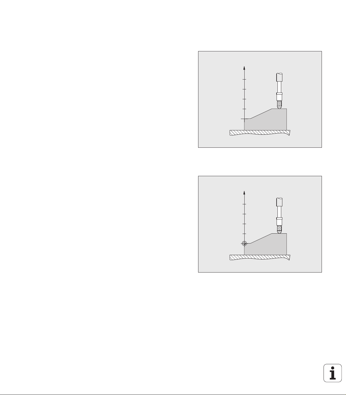
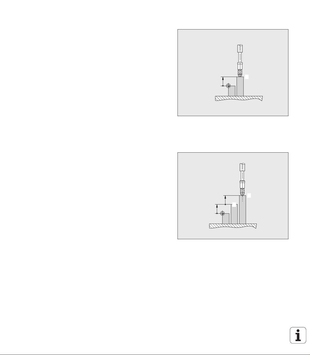
Datums
The workpiece drawing identifies a certain point on the workpiece
(usually a corner) as the absolute datum and perhaps one or more
other points as relative datums.
The datum setting procedure establishes these points as the origin of
the absolute or relative coordinate systems. The workpiece, which is
aligned with the machine axes, is moved to a certain position relative
to the length gauge and the display is set either to zero or to another
appropriate value.
I – 2 Fundamentals of positioning
Fig. I.2 Length gauge without datum setting:
Unknown assignment of measured values
to positions
Fig. I.3 Length gauge with datum setting: Known
assignment of measured values to positions
16 I Working with the ND 287 position display unit
Page 17
Actual position, nominal position and
R
I
S
distance-to-go
The position of the length gauge at any given moment is called the
actual position, while the position that the length gauge is to move
to is called the nominal position. The distance from the nominal
position to the actual position is called the distance-to-go (see Fig.
I.4).
Fig. I.4 Nominal position S, actual position I and
distance-to-go R
I – 2 Fundamentals of positioning
ND 287 17
Page 18
Absolute workpiece positions
0
20
1
0
10
10
2
3
Each position on the workpiece is uniquely identified by its absolute
coordinates (see Fig. I.5).
Example: Absolute coordinates of position 1: Z = 20 mm
If you are drilling or milling a workpiece according to a workpiece
drawing with absolute coordinates, you are moving the tool or length
gauge to the value of the coordinates.
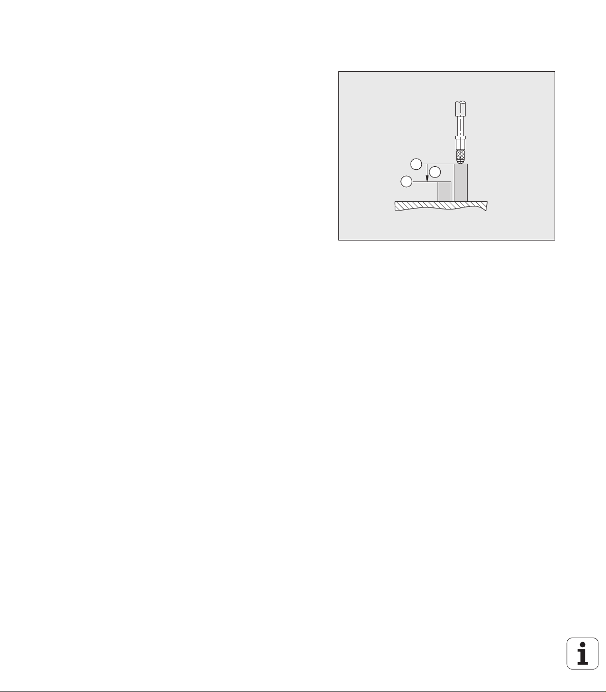
Incremental workpiece positions
I – 2 Fundamentals of positioning
A position can also be referenced to the preceding nominal position.
For this, the relative datum must be set to the preceding nominal
position. Such coordinates are referred to as incremental
coordinates (increment = increase). They are also called incremental
or chain dimensions (since the positions are defined as a chain of
dimensions). Incremental coordinates are identified by a preceding I.
Example: Incremental coordinate of position 3 referenced to position
2 see Fig. I.6.
Absolute coordinate of position 2: Z = 10 mm
Incremental coordinates of position 3: IZ = 10 mm
If you are drilling or milling a workpiece according to a workpiece
drawing with incremental coordinates, you are moving the tool or
length gauge by the value of the coordinates.
Fig. I.5 Position 1: definition through absolute
coordinates
Fig. I.6 Position 3: definition through incremental
coordinates
18 I Working with the ND 287 position display unit
Page 19
Incremental position encoders
Y
X
Z
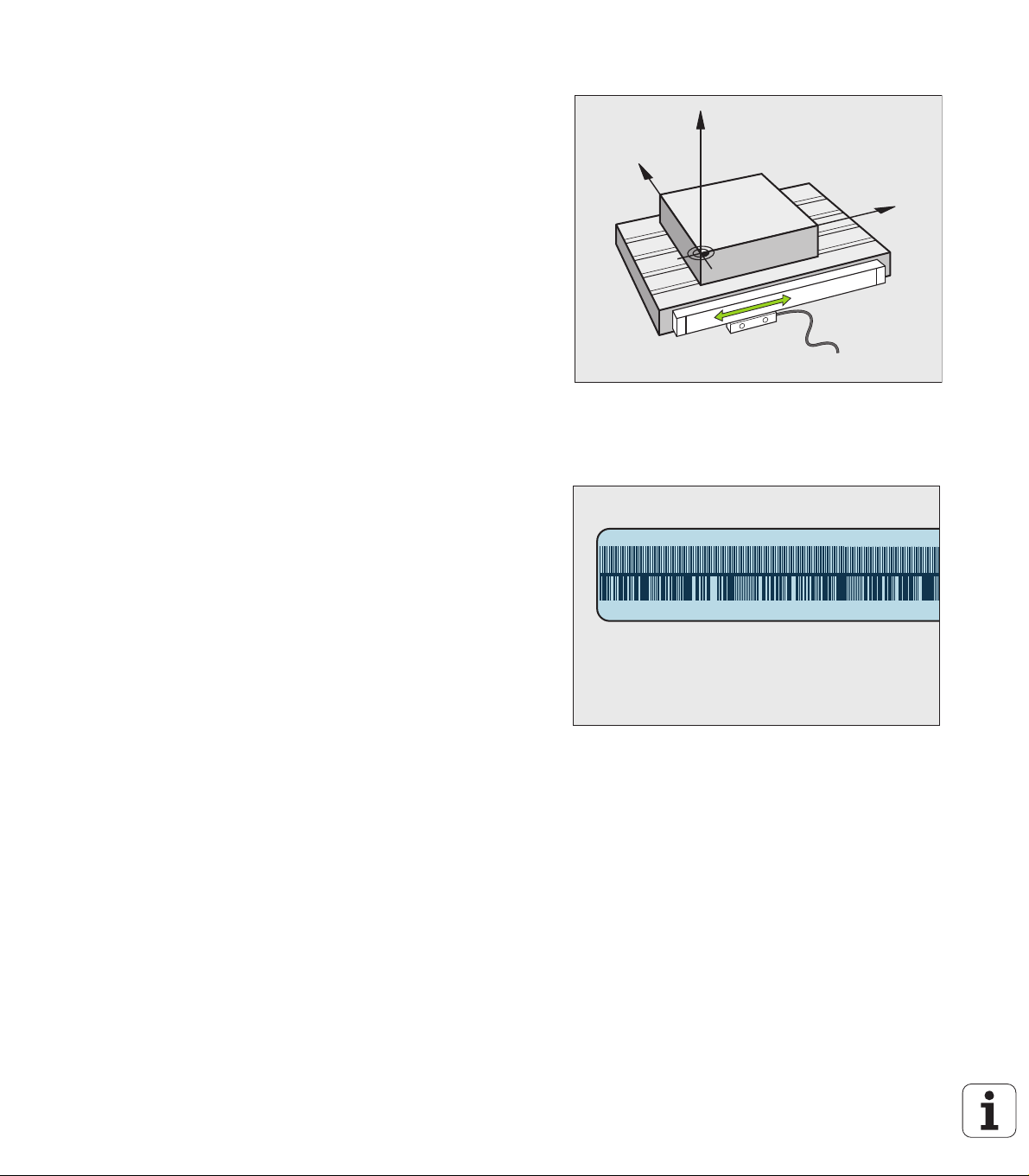
Incremental linear and rotary encoders from HEIDENHAIN convert the
movements of, for example, a length gauge into electrical signals. A
position display unit, such as the ND 287, constantly evaluates these
signals and calculates the actual positions of the length gauge, which
it displays as a numerical value on the screen.
If there is a power interruption, the calculated position will no longer
correspond to the actual position of the length gauge. When power is
restored, you can re-establish this relationship with the aid of the
reference marks on the position encoders and the ND 287's reference
mark evaluation feature.
Absolute position encoders
Fig. I.7 Linear position encoder, here for the X axis
Absolute linear and angle encoders from HEIDENHAIN transmit the
absolute position value to the position display unit immediately after
switch-on. This way the assignment of the actual position to the
position of, for example, a length gauge is re-established directly after
switch-on.
The encoder reads the absolute position information directly from the
scale graduation (see Fig. I.8), and transmits it serially to the position
display unit via the bidirectional EnDat interface.
I – 2 Fundamentals of positioning
Fig. I.8 Scale grating for absolute position encoders
ND 287 19
Page 20
Reference marks
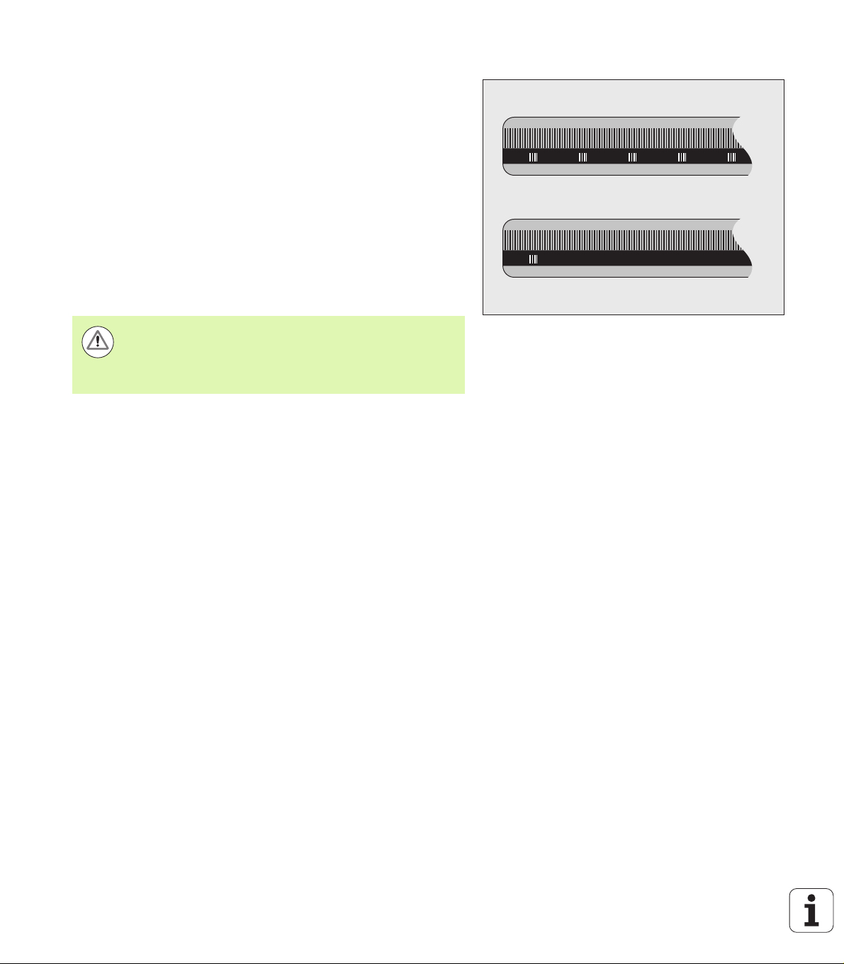
Encoders normally contain one or more reference marks (see Fig. I.9)
which the ND 287's reference mark evaluation feature uses to reestablish datum positions after a power interruption. There are two
main options available for reference marks: fixed and distance-coded.
Encoders with distance-coded reference marks have marks
separated by a specific encryption pattern that allows the ND 287 to
use any two pair of marks along the length of the encoder to reestablish the prior datums. This configuration means that the operator
only has to travel a very short distance, anywhere along the encoder,
to re-establish the datums when the ND 287 is turned back on.
Encoders with fixed reference marks have one or more marks on
fixed intervals. To re-establish the datums correctly, it is necessary to
use the same exact reference mark, during the reference mark
evaluation routine, that was used when the datum was first
established.
Danger to workpiece!
The established datums cannot be restored from one
power cycle to the next if the reference marks were not
crossed before the datums were set.
I – 2 Fundamentals of positioning
Fig. I.9 Linear scales – with distance-coded
reference marks (upper illustration) and one
reference mark (lower illustration)
20 I Working with the ND 287 position display unit
Page 21
I – 3 Basic functions of the ND 287
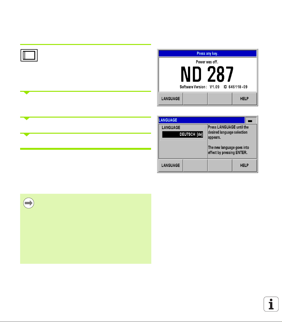
ND 287 power-up
Switch on the ND 287. The power switch is located
on the back of the ND. After switching the ND 287 on,
or after a power failure, the power-up screen will
appear (see Fig. I.10). The green LED on the front
panel lights up. The power-up screen shows the
position display unit model as well as the ID and
version number of the currently installed software.
Press the LANGUAGE soft key if you want to change the
conversational language (see Fig. I.11). Press ENTER to confirm your
selection.
Press the HELP soft key to call the integrated help system.
Fig. I.10 Power-up screen
Press any key to call the standard screen.
Your ND 287 is now ready for operation in the Actual Value operating
mode. If an incremental encoder is connected to the ND, the REF
symbol is flashing. At this point the reference mark evaluation should
be completed (see "Reference mark evaluation" on page 22).
If an absolute encoder is connected to the ND, the encoder
automatically transmits the absolute position value to the position
display unit.
If necessary, you can change the language later, see
"Language" on page 37.
To update your software version (firmware version), see
"Software update (firmware update) installation" on page
103.
The idle time after which the ND activates the screen
saver can be defined (factory default setting: 120 min,
see "Console adjustment" on page 37). The red LED on
the front panel lights up. To reactivate the screen, press
any key or move the encoder.
You can deactivate the power-up screen in order to
display the standard screen immediately after power up
(see "Counter settings" on page 77).
I – 3 Basic functions of the ND 287
Fig. I.11 Selecting the language
ND 287 21
Page 22
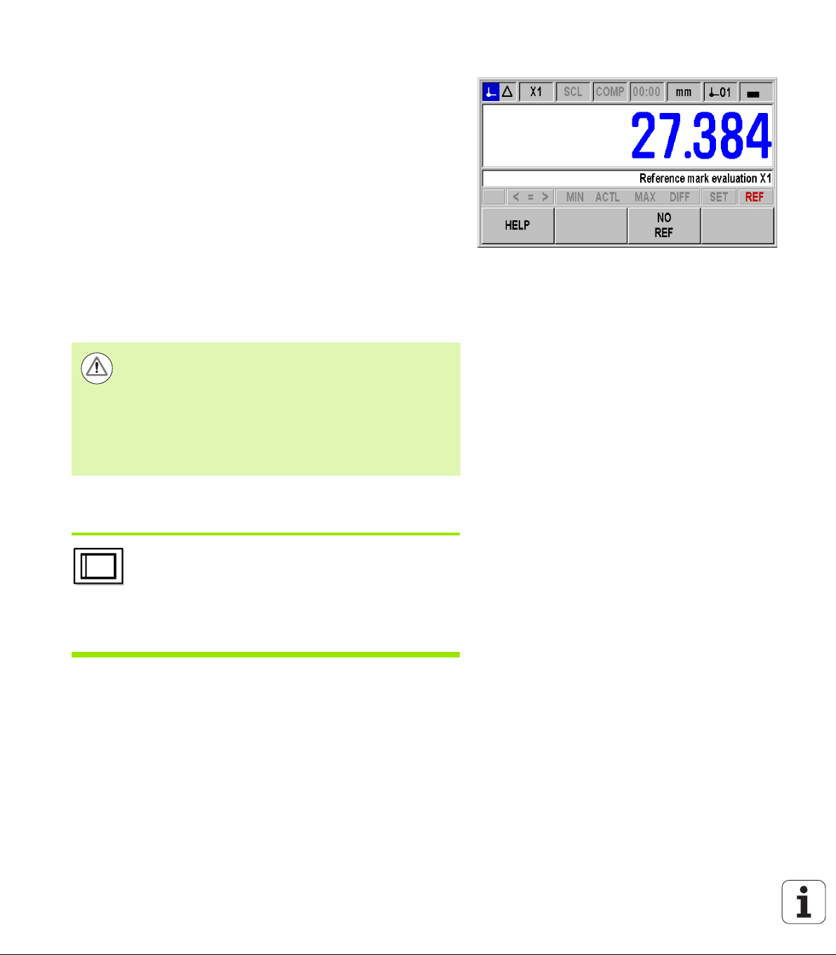
Reference mark evaluation
The ND 287's REF reference mark evaluation feature automatically reestablishes the relationship between axis-slide or length gauge
positions and display values that you last defined by setting the datum.
Reference mark evaluation if an incremental encoder is connected
(see Fig. I.12):
If the REF symbol is flashing, cross over the reference marks.
The REF mark evaluation feature determines the correct display
value and the REF symbol stops flashing.
Working without reference mark evaluation
Press the NO REF soft key to exit the reference mark evaluation
routine and continue.
In order to activate the reference mark evaluation feature at a later
time, you can apply an external signal to pin 25 at connection X41
(see "Setting up the encoder" on page 71), or you can switch the
ND 287 off and then back on.
Danger to workpiece!
If an encoder is set up without reference marks, or if the
I – 3 Basic functions of the ND 287
reference marks have not been crossed over, then the
REF indicator will appear dimmed, and datums set from
any axis will be lost once power is turned off. This means
that it is not possible to re-establish the relationship
between axis slide positions and display values after a
power interruption (switch-off).
Fig. I.12 Screen for establishing reference marks
ND 287 shutdown
Switch off the ND 287. The measured values of a
series of measurements will not be retained on a
power cycle. The parameter settings, the error
compensation tables or measured values that have
been saved during statistical process control will stay
in memory.
22 I Working with the ND 287 position display unit
Page 23
Standard screen layout
1
432
5
In addition to displaying position information, the ND 287 standard
screen also displays information on settings and operating modes at
any time (see Fig. I.13). The standard screen is divided into the
following areas:
1 Status bar
Current operating mode: Actual Value,
Distance-To-Go.
X1, X2 or X1:X2: Current display mode of axis or coupled axes.
SCL shown in black: Scale factor is active.
COMP shown in black: The error compensation or axis-error
compensation is active for the currently displayed axis or
coupled axes.
Elapsed time of running stopwatch: If the stopwatch is
stopped, the box appears dimmed.
MM, INCH, DEG, DMS or RAD: Currently active unit of
measure.
Currently active datum: The ND 287 allows you to work with
two different datums.
Indicates the soft-key page (soft-key row) you are currently on.
2 Position display
Length display:
Current axis value with algebraic sign.
Angle display:
Current angle value with algebraic sign and unit of measure for
display values in degrees, minutes or seconds.
When displaying the traversing speed in the series of
measurements mode, the ND 287 shows the unit of speed in
lowercase at the left edge of the screen.
3 Message line
The message line provides information on the required data
input or procedures, which is intended to support you in using
the position display unit.
If errors or warnings occur, they show up in red letters in the
message line. Acknowledge the message with the C key.
At the left edge of the message line the ND 287 displays a
measured-value counter in the series of measurements mode,
and a sample counter in the SPC mode.
If you have activated axis-error compensation with a
temperature sensor, the ND shows the value measured by the
temperature sensor at the left edge of the message line.
If a multiturn rotary encoder is connected, the ND shows the
number of revolutions at the right edge of the message line.
Fig. I.13 Standard screen
I – 3 Basic functions of the ND 287
ND 287 23
Page 24

4 Status display
5 Soft keys
I – 3 Basic functions of the ND 287
P0-P9: The symbol for the selected part becomes active once
you have activated the sorting and tolerance checking mode.
< / = / >: The first three symbols become active once you have
activated the tolerance checking and sorting mode, as well as
during Statistical Process Control (SPC). The symbols are
shown in red if the current value is less than the lower sorting
limit or greater than the upper sorting limit. Green indicates that
the value is within the two sorting limits.
MIN, ACTL or MAX and DIFF: The symbols are only active,
while a series of measurements is running. They indicate the
display mode you have selected.
Set: If you enter a new value during datum setting, the SET
symbol will start flashing.
REF: The REF symbol is flashing in red until the reference mark
evaluation for the displayed axis has been completed (if an
incremental encoder is connected).
The NAVIGATION key (shown at left) allows you to move
through the three pages of selectable soft-key functions.
Press the corresponding soft key directly below each soft
key label to execute the soft-key function. The soft-key
assignment varies depending on the ND's operating
mode.
24 I Working with the ND 287 position display unit
Page 25
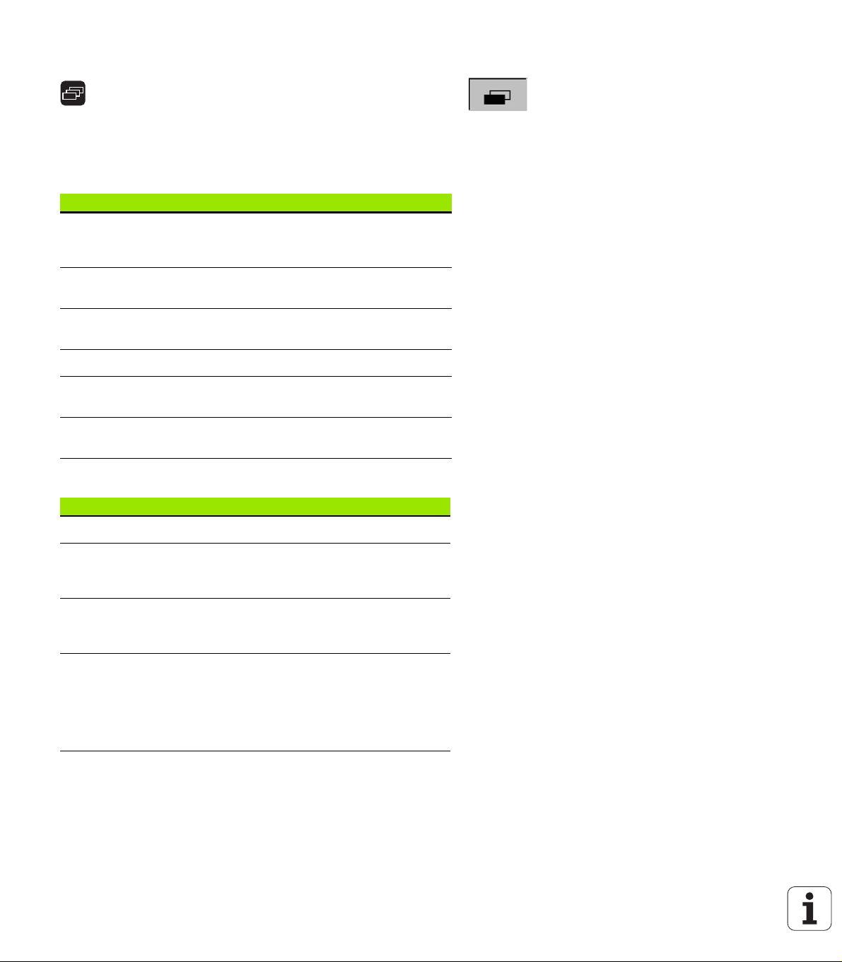
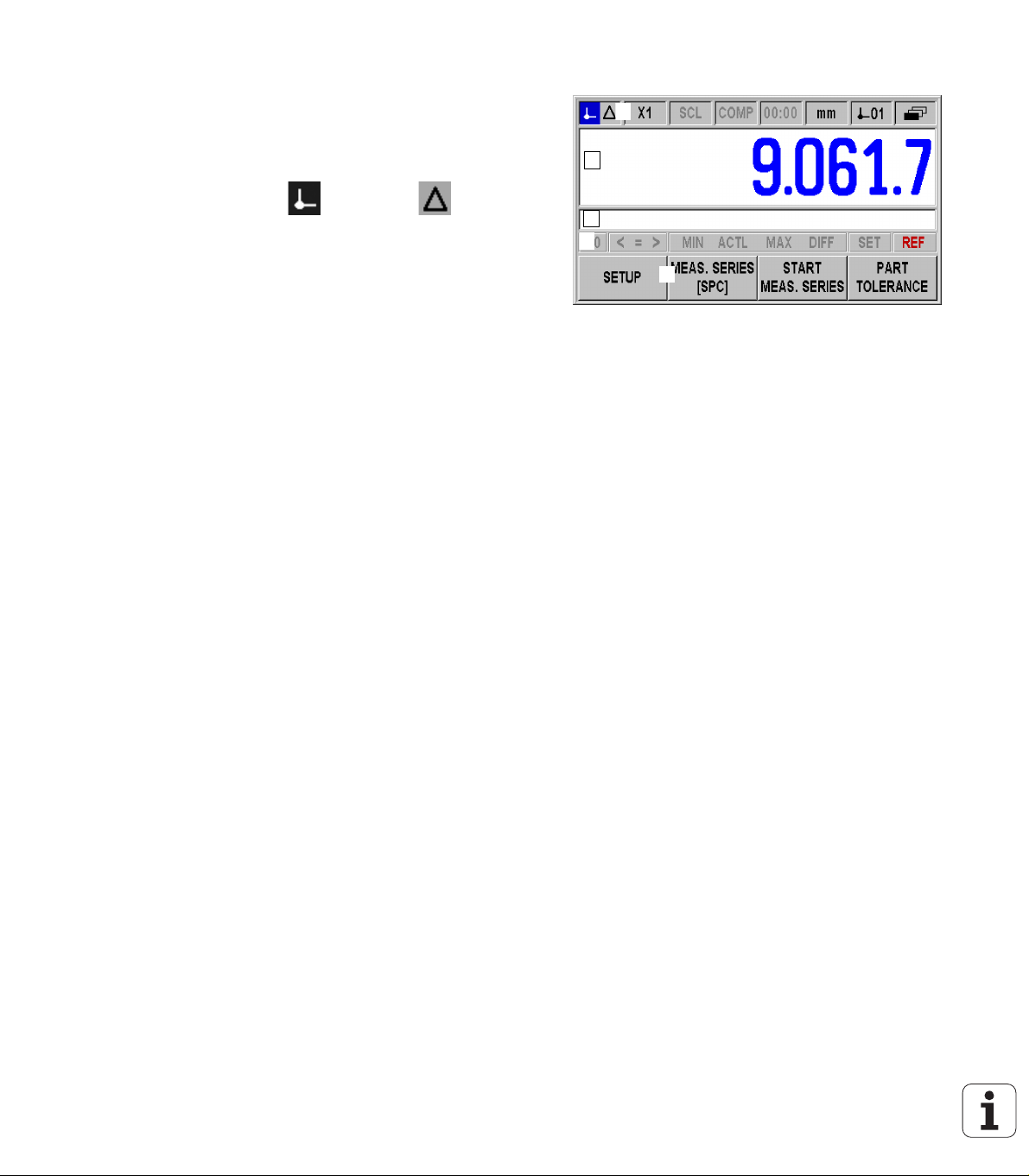
Soft-key functions on the standard screen
There are three pages (rows) of soft-key functions. Use the
NAVIGATION key (shown at left) to move through the pages.
The page indicator in the status bar shows the number of
pages. The darkened page indicates the page you are currently
on. This manual provides more information about each soft key
on the pages indicated in the table below.
Soft key page 1:
Soft key Function Page
SETUP Opens the JOB SETUP menu and
provides access to the
INSTALLATION SETUP soft key.
Page 30
Fig. I.14 Page indicator
MEAS.
SERIES
START MEAS.
SERIES
SPC Opens the SPC menu. Page 49
START
SPC
PART
TOLERANCE
Soft key page 2:
Soft key Function Page
HELP Calls the integrated help system. Page 28
PRINT Transmits the current measured
Distance-to-goonSwitches the display between
MM
inch
DEG
DMS
rad
Opens the SERIES OF
MEASUREMENTS menu.
Starts a series of measurements. Page 48
Starts the SPC function. Page 56
Opens the SELECT PART menu. Page 58
value to a connected PC or printer
via the serial interface.
operating modes Actual Value/
Distance-To-Go.
Switches the position display
(length or angle) to the displayed
unit of measure. The selected unit
of measure is shown in the status
bar.
Page 42
Page 113
Page 30
Page 34
I – 3 Basic functions of the ND 287
Soft key page 3:
ND 287 25
Page 26

Soft key Function Page
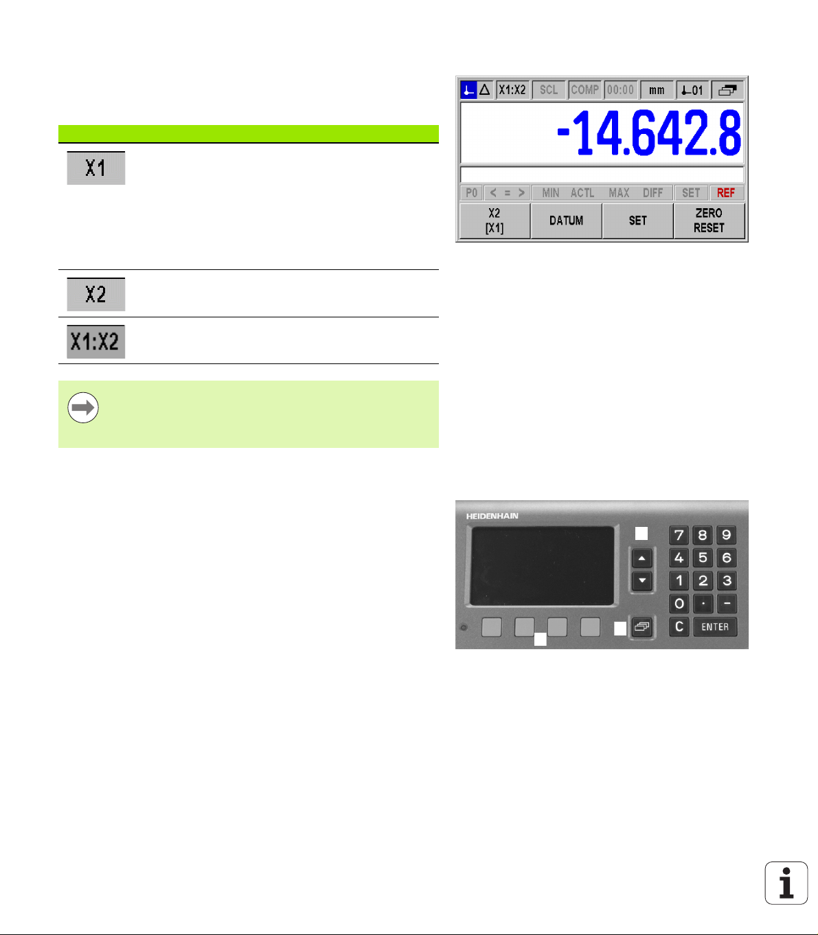
X1
[X2]
DATUM Switches the datum (see datum display in the status bar). Page 31, Page 36,
This function is only available if the ND is configured for two axes:
Switches the display mode in the status bar (X1, X2, X1:X2) and the display
value.
The upper axis designation indicates the displayed axis, here X1. The lower
axis designation in brackets (here, X2) appears in the respective field if you
press the soft key again. Press the soft key repeatedly for the following
display values: X1, X2, X1+X2, X1-X2 and formula f(X1, X2).
Page 27, Page 77
I – 3 Basic functions of the ND 287
PRESET Sets the axis value to the preset value for the datum.
If a coupled position X1:X2 is active, the ND sets X1 to the preset value for
the datum and resets X2 to zero..
RESET Actual Value mode: Resets the selected datum of the displayed axis to zero.
MEASURE
REF. PART
If a coupled position is active, the ND resets the selected datum for both axes
to zero.
Distance-To-Go mode: Resets the distance-to-go for the displayed axis to
zero. If a coupled position is active, the ND resets the distance-to-go for both
axes to zero.
Display the measured values of a reference part: If temperature compensation
using a reference part is activated, the ND 287 displays the actual measured
temperature value on the left side of the message line, and the entered nominal
dimension of the reference part on the right side.
Page 31
Page 31
Page 41
26 I Working with the ND 287 position display unit
Page 27
Axis display mode
123
Press the X1-X2 [f(X1,X2)] soft key to select the desired display mode
and the corresponding display value (see "Soft-key functions on the
standard screen" on page 25):
Status bar Function
Display mode of axis X1 or input X1
If an analog sensor is connected to
input X2 and the ENCODER TYPE
field under Encoder Setup is set to
COMPENSATION, (see "Setting up
the encoder" on page 71) the ND 287
behaves in the same way as a singleaxis display unit (only X1).
Display mode of axis X2 or input X2
Display mode for both axes: Display for
X1+X2, X1-X2 or f(X1,X2).
Fig. I.15 Standard screen with soft-key page 3
If you want to enter a formula for (X1,X2), select the
formula editor, see "Counter settings" on page 77. There
you can also define the possible display modes of the
axes.
Data input
Use the keypad to enter numeric values within each field.
The ENTER key will confirm the entry within a field and return to the
previous screen.
Press the C key to clear entries, acknowledge error messages or
return to the previous screen.
Soft-key labels 1 show the various operating and parameter-setting
functions. These functions are selected by pressing the
corresponding soft key directly below each soft key label. The
soft-key functions are usually arranged in up to three soft-key pages.
Use the NAVIGATION key 2 to move through the soft-key pages
(see below).
The NAVIGATION key 2 moves through the pages of available
soft-key functions. The current page will be highlighted in the status
bar at the top of the screen.
Use the UP or DOWN arrow key 3 to move between fields within a
form or menu items (parameters) of a menu. The orientation of the
cursor is such that it will return to the top once it has reached the
bottom of the menu.
I – 3 Basic functions of the ND 287
Fig. I.16 Data input
ND 287 27
Page 28
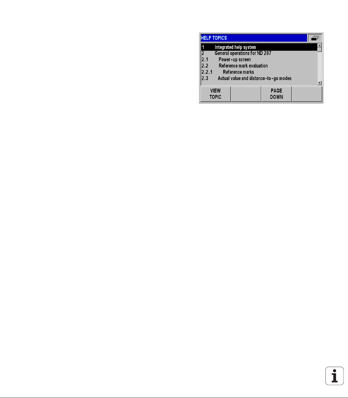
Integrated help system
The integrated help system provides appropriate information and
assistance in any situation (see Fig. I.17).
To call the integrated help system:
Press the HELP soft key.
Information relevant to the current operation will be displayed.
Use the UP or DOWN arrow keys or the PAGE UP or DOWN soft
keys if the explanation is spread over more than one screen page.
To view information on another topic:
Press the LIST OF TOPICS soft key to view the index of the help
topics.
Press the PART 1/[PART 2] soft key to call the extended help, which
is available in exceptional cases.
Press the UP or DOWN arrow key or the PAGE UP or PAGE DOWN
soft key to scroll through the index.
Press the VIEW TOPIC soft key or the ENTER key to select the item
you need.
To leave the integrated help system:
Press the C key. The ND will return to the screen from which you
I – 3 Basic functions of the ND 287
called the help system.
Fig. I.17 Integrated help system
28 I Working with the ND 287 position display unit
Page 29
Data input forms
Information required for various operational functions and setup
parameters is entered through a data input form. These forms will
appear after selecting features that require any additional information.
Each form provides specific fields for entering the required
information.
To confirm the changes:
Press the ENTER key.
To ignore the changes and return to the previous screen:
Press the C key.
Instruction box messages
Whenever a menu or form is open, an instruction box will also open
immediately to the right of it (see Fig. I.18). This message box will
provide information to the operator on what the chosen function does
and present instructions on the available options.
I – 3 Basic functions of the ND 287
Fig. I.18 Example of instruction box messages
Error messages
If an error occurs while you are working with the ND, the message will
appear on the display and provide an explanation of what caused the
error.
To acknowledge the error message:
Press the C key.
If a new error occurs before the last error has been
acknowledged, the last error that has occurred will be
displayed. After the last error has been acknowledged, the
previous error will be displayed again. The ND always
stores the last error of each error category for
acknowledgment (see "Error messages" on page 60).
ND 287 29
Page 30
I – 4 Job Setup
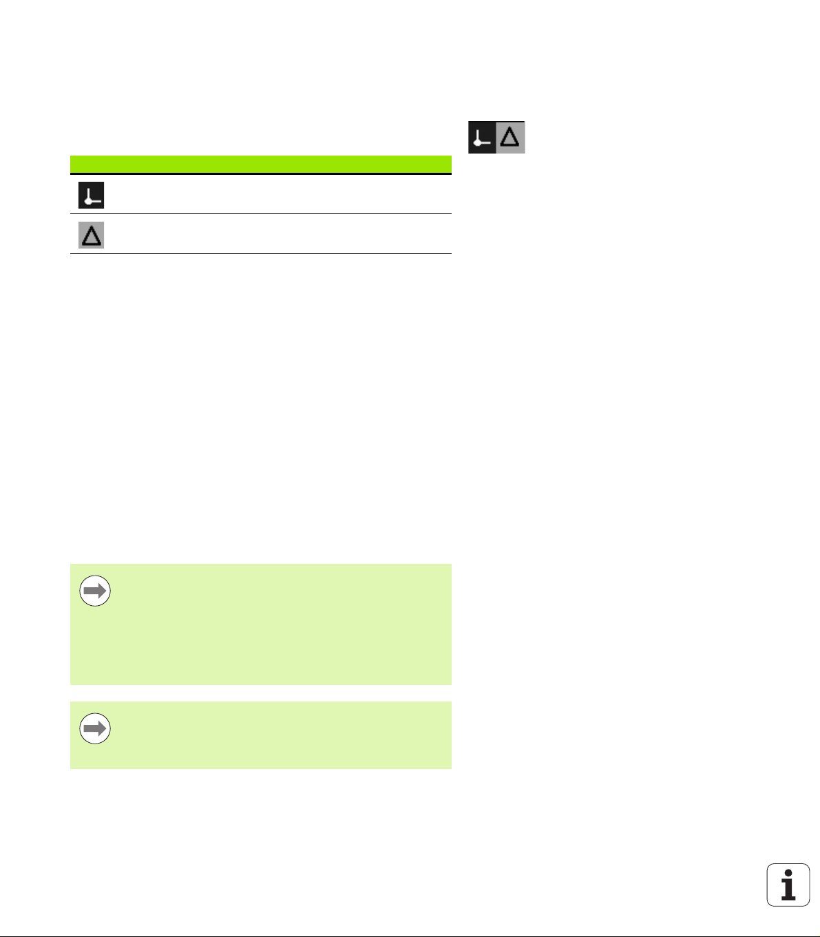
Operating modes
The ND 287 has two operating modes: Actual Value and Distance-
To-Go.
Status bar Function
I – 4 Job Setup
In the Actual Value operating mode, the ND 287 always displays the
current actual position of the length gauge, relative to the active
datum. In this mode, all moves are done by traveling until the display
matches the nominal position that is required.
The Distance-To-Go feature enables you to approach nominal
positions simply by traversing to display value zero. Proceed as
follows:
Press the DELTA MODE ON soft key to switch the operating mode
(see "Soft-key functions on the standard screen" on page 25): The
display value is zero.
Use the numeric keys to enter the nominal position you want to
move to and confirm with the ENTER key: The distance-to-go is
displayed.
Traverse the axis until the display value is zero.
If required, enter the next nominal position and confirm with the
ENTER key: Traverse the axis until the display value is zero.
To leave the Distance-To-Go operating mode: Press the DELTA
MODE OFF soft key.
Shows current actual position
Displays current distance from the
nominal position
Fig. I.19 Actual Value symbol (highlighted) in the
status display
Algebraic sign of distance-to-go:
The distance-to-go has a positive sign if the axis
direction from the actual towards the nominal position is
negative.
The distance-to-go has a negative sign if the axis
direction from the actual towards the nominal position is
positive.
In the Distance-To-Go operating mode, the switching
outputs A1 (pin 15) and A2 (pin 16) have a different
function (see "Switching outputs at D-sub connection
X41" on page 95).
30 I Working with the ND 287 position display unit
Page 31

Datum setting
The datum setting procedure assigns the matching display value to a
known position. With the ND 287 position display unit, you can set
two separate datum points.
During operation, you can reset the display value of the axis to zero, or
preset it to a defined or new value.
With RESET, you set the current datum to zero at the
current position for that axis:
If the Actual Value mode is active, the display value is
zero.
If the Distance-To-Go mode is active, the distance
remaining to the position of the new datum is displayed.
Setting the display value for one axis or for two axes in the X1 or X2 display mode
Select soft-key page 3 on the standard screen.
Select display mode X1 or X2 (see "Axis display mode" on page 27).
If necessary, press the DATUM soft key to select the datum you
want to set.
To reset the display value to zero, press the RESET soft key or apply
a signal to pin 2 of connection X41. As an alternative, you can use
the numeric keys to enter the number zero and press ENTER to
confirm your entry.
You can also set any desired display value by entering the new value
with the numeric keypad. As a result, the SET symbol in the status
display starts flashing in red. Press the ENTER key to confirm the
entered numerical value.
To set the display value to the preset value for the datum point (see
"Value for datum point" on page 36), press the PRESET soft key. As
an alternative, you can apply a signal to pin 3 of connection X41.
I – 4 Job Setup
Fig. I.20 Standard screen with soft-key page 3
ND 287 31
Page 32

Setting the display value for two axes in display mode X1:X2 (applies to X1+X2, X1-X2, f(X1,X2))
Select soft-key page 3 on the standard screen.
Select display mode X1:X2 (see "Axis display mode" on page 27).
If necessary, press the DATUM soft key to select the datum you
want to set.
To reset the display value of both axes to zero, press the RESET
soft key or apply a signal to pin 2 of connection X41. As an
alternative, you can use the numeric keys to enter the number zero
I – 4 Job Setup
and press ENTER to confirm your entry. Depending on the formula
programmed for the coupled position, the display value does not
necessarily need to be zero.
You can also set axis X1 to any desired display value by entering the
new value with the numeric keypad. As a result, the SET symbol in
the status display starts flashing in red. Press the ENTER key to
confirm the entered numerical value. The display value of axis X2 is
automatically reset to the value zero.
To set axis X1 to the preset value for the datum point (see "Value for
datum point" on page 36), press the PRESET soft key. The display
value of axis X2 is automatically reset to the value zero. As an
alternative, you can apply a signal to pin 3 of connection X41.
Fig. I.21 Standard screen with soft-key page 3
Fig. I.22 Sum or difference display
32 I Working with the ND 287 position display unit
Page 33

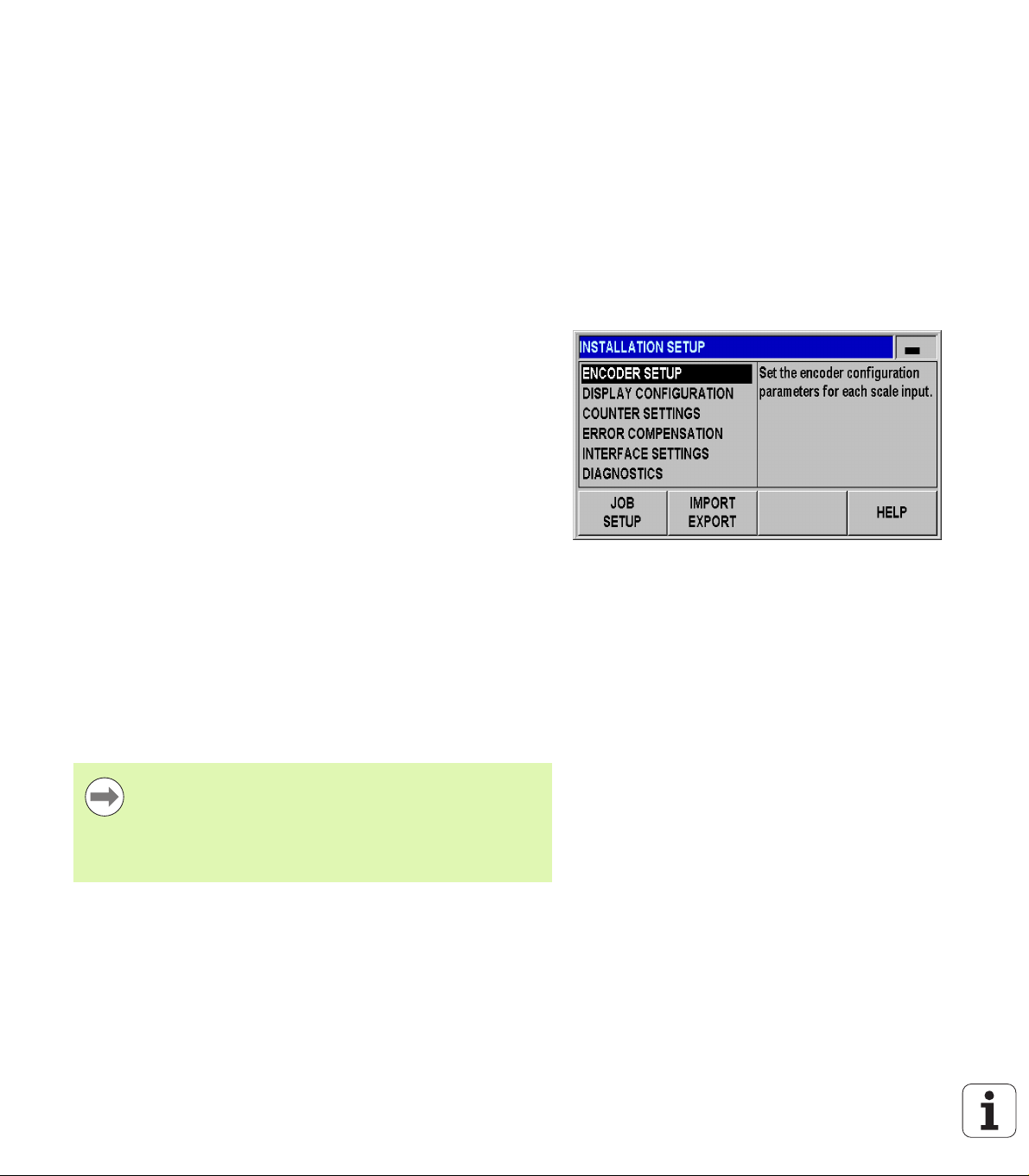
Calling the JOB SETUP menu
The ND 287 offers two categories for setting up operating
parameters: JOB SETUP and INSTALLATION SETUP.
The JOB SETUP parameters are used to accommodate specific
machining requirements for each job.
The INSTALLATION SETUP menu is used to establish encoder,
display and communication parameters (see "INSTALLATION
SETUP menu" on page 70).
To call the JOB SETUP menu:
Press the SETUP soft key to open the JOB SETUP menu.
When in the JOB SETUP menu, the following soft keys will be
available (see Fig. I.23):
INSTALLATION SETUP
Press to begin accessing the INSTALLATION SETUP parameters
(see "INSTALLATION SETUP menu" on page 70).
IMPORT/EXPORT
Operating parameter information can be imported or exported over
the serial port. (See "Serial data transfer with the Import or Export
function" on page 101). Press this soft key to call the two following
soft keys:
Press IMPORT to download operating parameters from a PC.
Press EXPORT to upload the current operating parameters to a PC.
To exit, press the C key.
HELP
This soft key will open on-line help.
Press the NAVIGATION key to move through the pages of menu
parameters. To view and change menu parameters, use the UP/
DOWN arrow key to highlight the parameter of interest and press the
ENTER key.
On the following pages you will find more information on the menu
parameters.
I – 4 Job Setup
Fig. I.23 JOB SETUP menu
Fig. I.24 JOB SETUP menu
ND 287 33
Page 34

Unit of measure
The UNITS OF MEASURE form is used to specify the preferred display
units and formats for linear and angular measurements. The ND 287
powers up with these settings in effect.
In the LINEAR field, define the unit of measure for linear
measurement:
In the JOB SETUP menu, select UNITS and press the ENTER key to
open the form.
I – 4 Job Setup
Use the MM/INCH soft key to switch between MM and INCHES.
This can be performed in either Actual Value or Distance-To-Go
mode.
In the ANGULAR field, define the format and input mode for angles.
Press the ANGLE soft key to switch between DECIMAL DEGREES,
RADIANS and DMS (degrees/minutes/seconds).
The defined unit of measure is shown in the status bar on the standard
screen.
Fig. I.25 Unit of measure
34 I Working with the ND 287 position display unit
Page 35

Scaling factor
The scaling factor is used to scale the part up or down. All encoder
movements are multiplied by the scaling factor.
A scaling factor of 1.0 creates a part with the exact size as
dimensioned on the print.
A scaling factor > 1 enlarges the workpiece.
A scaling factor < 1 reduces the workpiece.
To define the scaling factor:
In the JOB SETUP menu, select SCALE FACTOR and press the
ENTER key to open the form.
The ON/OFF soft key is used to disable the current scaling factors.
Use the numeric keys to enter a number greater than zero if a
scaling factor is active. The number range is 0.100000 to 10.000000.
When the scaling factor is a value other than 1, the scaling symbol
SCL is shown in black in the status bar.
The settings for the scaling factor will be retained on a power cycle.
I – 4 Job Setup
Mirror: A scaling factor of –1.00 will produce a mirror
image of the part. You can both mirror and scale a part
at the same time.
Fig. I.26 Scaling factor
ND 287 35
Page 36

Value for datum point
This form is used to set a value for a datum point (see Fig. I.27).
In the JOB SETUP menu, select VALUE FOR DATUM POINT and
press the ENTER key to open the form.
Enter the value and press ENTER to confirm your entry.
If you want to set the display value to this value, press the PRESET
soft key on the standard screen (see "Datum setting" on page 31) or
activate pin 3 at D-sub connection X41 (see "Switching inputs at D-
I – 4 Job Setup
sub connection X41" on page 93).
Stopwatch
The stopwatch shows the hours (h), minutes (m), seconds (s). It
operates like a stop watch showing elapsed time. The clock starts
timing from 0:00:00.
The ELAPSED TIME field shows the total accumulated time from each
interval (see Fig. I.28).
In the JOB SETUP menu, select STOPWATCH and press the ENTER
key to open the form.
Press the START/STOP soft key. The ND 287 shows the status field
RUNNING and the elapsed time. Press it again to stop time from
elapsing.
Press the RESET soft key to reset the elapsed time. Resetting will
stop the clock if it is running (STOPPED).
Fig. I.27 Value for datum point
Fig. I.28 Stopwatch
All stopwatch functions (START, STOP, and RESET) are
applied immediately.
The status bar shows minutes and seconds for an
elapsed time of less than 1 hour. Hours and minutes are
shown for a time of 1 hour or more.
36 I Working with the ND 287 position display unit
Page 37

Console adjustment
You can adjust the brightness of the ND 287's LCD display (see Fig.
I.29):
In the JOB SETUP menu, select CONSOLE ADJUSTMENT and
press the ENTER key to open the form.
Press the DECREASE or INCREASE soft key to adjust the
brightness to your requirements.
The DISPLAY SAVER setting is the amount of time the system is
idle before the LCD is turned off. The idle time may be set from 30
to 120 minutes. The display saver can be disabled during the current
power cycle by pressing the DISABLE soft key.
I – 4 Job Setup
You can also use the UP or DOWN arrow key to adjust the
LCD's brightness directly on the screen.
Language
The ND 287 supports multiple languages. To change the language:
In the JOB SETUP menu, select LANGUAGE and press the ENTER
key to open the form.
Press the LANGUAGE soft key until the desired language appears in
the LANGUAGE field.
Press ENTER to confirm your selection.
Fig. I.29 Console adjustment
Fig. I.30 Language
ND 287 37
Page 38

Switching signals
Danger to internal components!
The power supply of external circuits must comply with
EN 50178 requirements for low voltage electrical
separation.
Connect inductive loads only with a quenching diode
parallel to the inductance.
I – 4 Job Setup
Danger to internal components!
Use only shielded cables and connect the shield to the
connector housing.
In the JOB SETUP menu, use the DOWN arrow key to select
SWITCHING SIGNALS, and press the ENTER key to open the form.
Press the ON/OFF soft key to activate/deactivate the trigger points.
Using the numeric keys, enter the desired trigger limits A1 and A2.
When the trigger limits defined by parameter are reached, the
corresponding output becomes active. Output A1 represents pin 15
at D-sub connection X41, and output A2 represents pin 16:
Pin 15 remains active as long as the measured value is greater than
or equal to A1.
Pin 16 remains active as long as the measured value is greater than
or equal to A2.
A separate output is available for trigger point zero. If the display value
is zero, the position display unit always activates pin 14 at D-sub
connection X41. The minimum signal duration is 180 ms.
The ND 287 constantly monitors the measuring signal, the input
frequency, the data output, etc., and displays errors in the message
line. If errors occur that seriously influence measurement or data
output, the ND activates the switching output at pin 19. The output
remains active until the error has been acknowledged. This makes it
possible to monitor proper function during automated processes.
Fig. I.31 Switching signals
In the Distance-To-Go operating mode, the switching
outputs A1 (pin 15) and A2 (pin 16) have a different
function (see "Switching outputs at D-sub connection
X41" on page 95).
38 I Working with the ND 287 position display unit
Page 39

Measured-value output
1
2
3
4
With the measured value output feature, the current display values
can be transmitted over the serial port. Output of the current display
values is activated via a switching signal at D-sub connection X41,
the command CTRL B, or the PRINT soft key (see "Measured value
output" on page 113).
The effect the signal for measured value output has on the display
value on the screen can be defined as follows:
In the JOB SETUP menu, select MEASURED VALUE OUTPUT and
press the ENTER key to open the form.
Press the DISPLAY FREEZE soft key. Three different settings are
available:
CONCURRENT DISPLAY: The display is not stopped during
measured value output. The display value is the current measured
value.
FROZEN/CONCURRENT DISPLAY: The display is stopped during
measured value output and remains stopped while the switching
input is active.
FROZEN DISPLAY: The display is stopped, but is updated by
every measured value output.
The following figure illustrates the different settings for measured
value output.
I – 4 Job Setup
Fig. I.32 Measured-value output
1 Position
2 Latch signal
3 Frozen display
4 Frozen/concurrent display
For more information on measured value output, refer to Page 113.
ND 287 39
Page 40

Function of external inputs
Danger to internal components!
The power supply of external circuits must comply with
EN 50178 requirements for low voltage electrical
separation.
Connect inductive loads only with a quenching diode
parallel to the inductance.
I – 4 Job Setup
Danger to internal components!
Use only shielded cables and connect the shield to the
connector housing.
The function for hiding possible display modes of the axes
(see page 78) is always active.
Use FUNCTION EXT. INPUTS in the JOB SETUP menu to determine
the ND 287's reaction to the external inputs at connection X41 (see
"Switching inputs at D-sub connection X41" on page 93).
In the JOB SETUP menu, select FUNCTION EXT. INPUTS and press
the ENTER key to open the form.
Press the VERSION soft key. Two different versions are available:
VERSION 1: You can externally activate the minimum/
maximum measurement for measurement series if the signal
at pin 6 remains permanently LOW. The SELECT DISPLAY soft
key for selecting the display mode becomes ineffective. Pin 7
sets the display to MIN, pin 8 to MAX and pin 9 to DIFF. The
display can only be set to ACTL if either none of the pins 7, 8 or 9
or more than one of the pins carries a signal. A signal (pulse) at
pin 5 starts a new series of measurements if the signal at pin 6
is permanently LOW.
VERSION 2: If pins 5, 6, 7, 8 or 9 are activated, the display modes
are switched to operation with two axes. Pin 6 switches to
axis X1, pin 7 to axis X2, pin 8 to the sum of the two axes X1+X2,
pin 9 to the difference between the two axes X1-X2 and pin 5
switches to the definable relationship between the two axes
f(X1,X2), see "Formula for coupled position" on page 78.
An overview of the switching inputs and outputs is provided on
Page 93.
Fig. I.33 External inputs function
40 I Working with the ND 287 position display unit
Page 41

Compensation using a reference part
Select the REFERENCE PART COMP. menu item to activate
temperature compensation using a reference part. Prerequisites:
A temperature sensor is connected to encoder input X2.
For the temperature sensor, you have set the ENCODER TYPE field
in the ENCODER SETUP menu to COMPENSATION and entered
the following encoder parameters, see "Setting up the encoder",
page 71:
Calibration pair of values
Correct thermal expansion coefficient
Reference temperature
The compensation value C is calculated as follows:
C = ND * E * (T - T_r)
ND: Nominal dimension of reference part
E: Expansion coefficient
T: Temperature currently being measured
T_r: Reference temperature
To activate the compensation:
In the JOB SETUP menu, select REFERENCE PART COMP. and
press the ENTER key to open the form.
Enter the known nominal dimension of the reference part in the
NOMINAL DIMENSION field.
Press the ON/OFF soft key to activate the temperature
compensation using a reference part in the MEASURE REF. PART
field.
To measure the reference part:
Press the MEASURE REF. PART soft key in the 3rd soft key row of
the standard screen. The ND 287 displays the current temperature
value on the left side of the message line, and the entered nominal
dimension of the reference part on the right side.
Insert your reference part and press either the ZERO soft key or the
NOMINAL DIMENSION soft key, depending on whether you want
to display the test objects' deviations from zero or from the nominal
dimension.
I – 4 Job Setup
Fig. I.34 Compensation using a reference part
ND 287 41
Page 42

I – 5 Series of measurements and
statistical process control
Functions
In addition to displaying measured values, the ND 287 can record and
evaluate measured values as a series of measurements, and can
perform Statistical Process Control (SPC).
You can record series of measurements with up to 10000 measured
process control
values per connected axis. The recording of the measured values
can be initiated manually, externally or according to time. After the
series of measurements has been recorded, you can immediately
evaluate it on the ND 287 and display it as a table or a graph. The
measured values can also be exported.
For statistical process control, the ND 287 can store up to 1000
measured values in a non-volatile FIFO memory. After the required
parameters have been defined and SPC has been started, samples of
the measured values to be monitored are recorded. After a sufficient
number of measured values has been recorded, the measured values
accumulated so far can be evaluated. In addition to displaying the
measured values, basic statistical data and a histogram, the ND 287
can also calculate and display the process capability indices Cp and
Cpk as well as various quality control charts. For fundamentals on
quality capability characteristics, refer to ISO 21747.
Switching between series of measurements and SPC mode
I – 5 Series of measurements and statistical
To switch between the MEAS. SERIES and SPC mode:
Press the MEAS. SERIES [SPC] or SPC [MEAS. SERIES] soft key
(depending on which of the two soft keys is displayed) in the first
soft-key row of the standard screen.
This opens the SERIES OF MEASUREMENTS or SPC -
STATISTICAL PROCESS CONTROL menu.
To switch the mode, press the MEAS. SERIES [SPC] or SPC [MEAS.
SERIES] soft key.
Fig. I.35 Measurement Series [SPC] mode
42 I Working with the ND 287 position display unit
Page 43

Calling the SERIES OF MEASUREMENTS menu
All parameters required for a series of measurements and the
possibility of analyzing a previously recorded series of measurements
are provided by the SERIES OF MEASUREMENTS menu.
To call the SERIES OF MEASUREMENTS menu, press the MEAS.
SERIES [SPC] soft key in the first soft-key row of the standard
screen.
Use the MEAS. SERIES ANALYSIS, MEAS. SERIES SETUP, MEAS.
SERIES DISPLAY , RECORD MODE and POS / SPEED DISPLAY
parameters to define further settings.
In the following sections you will find more detailed information on the
menu parameters.
Analysis of series of measurements
The ND 287 provides the following possibilities for analyzing the
recorded series of measurements:
Call the SERIES OF MEASUREMENTS menu.
Select MEAS. SERIES ANALYSIS. This opens an overview of the
statistical data of the series of measurements: Number of
measured values, maximum and minimum measured value,
difference (MAX-MIN, also referred to as range), mean value and
standard deviation.
If you have recorded the measured values of both axes, you can
switch between the measured-value analyses of the two axes with
the X1 [X2] soft key.
Press the EXPORT soft key to transfer the recorded data to a PC.
Press the GRAPH soft key to call a graphic display of all measured
values, including the minimum, maximum and mean values of the
measurement series. If the sorting and tolerance checking mode is
active, the ND 287 also enters the sorting limits into the graph.
Press the MEASURED VALUES soft key to open a table with all
recorded values. The measured values are listed in table format
(24 measured values per page). If the sorting and tolerance checking
mode is active, all measured values that are outside the sorting
limits are displayed in red in the table.
Use the PAGE UP or PAGE DOWN key to scroll through the table
one page at a time.
Press the STATISTICAL DATA soft key to return to the overview of
statistical data.
Fig. I.36 SERIES OF MEASUREMENTS menu
Fig. I.37 Statistical data of series of measurements
Fig. I.38 Diagram
process control
I – 5 Series of measurements and statistical
ND 287 43
Page 44

Setting up a series of measurements
To define the parameters of the series of measurements:
Call the SERIES OF MEASUREMENTS menu.
Select MEAS. SERIES SETUP.
In the RECORD MEAS. VALUES field, activate or deactivate
measured-value recording for a series of measurements.
In the RECORD field, select the trigger for recording the measured
values of a series of measurements. Press the RECORD soft key to
select one of the following possibilities:
process control
Sampling interval
External signal at connection X41 (pin 22 or 23)
ENTER key
Press the DOWN arrow key or the NAVIGATION key to display
further parameters.
The ND 287 can store a maximum of 10000 measured
values per axis. The measured values recorded in a series
of measurements will only be retained in memory until
power is switched off.
If you have selected EXTERNAL SIGNAL or ENTER key, another
parameter needs to be defined:
In the NO. MEAS. VALUES field, you enter the number of measured
values for the series of measurements. If you enter the value zero,
the ND deactivates the RECORD MEASURED VALUES function.
Fig. I.39 Setting up a series of measurements
Fig. I.40 Setting up a series of measurements
I – 5 Series of measurements and statistical
44 I Working with the ND 287 position display unit
Page 45

If you have selected SAMPLING INTERVAL, the two following
parameters in the second soft-key row are available for the exact
definition of the interval:
In the TIME SLOT field, define the duration of the series of
measurements in hours/minutes/seconds. Use the ← and → soft
keys to move from hours to minutes and seconds, and vice versa.
Use the numeric keys to enter the desired value. The maximum
possible duration of a measurement series is 999 hours, 59
minutes and 59 seconds.
In the SAMPLING INTERVAL field, enter the amount of time until a
measured value is recorded. Press the DECREASE or INCREASE
soft key to decrease or increase the value shown in the field: 20 ms
to 80 ms in increments of 20 ms, 100 ms to 900 ms in increments
of 100 ms, 1 s to 9 s in increments of 1 s and 10 s to 50 s in
increments of 10 s, 1 min to 9 min in increments of 1 min and
10 min to 30 min in increments of 10 min.
On the basis of the settings you defined for the sampling interval,
the ND 287 calculates the number of measured values for the series
of measurements and displays it in the NO. MEAS. VALUES field.
The measured values can be sorted and the sorting result
can be displayed in color during the series of
measurements to enable you to intervene, if required (see
"Sorting and tolerance checking" on page 58).
process control
Fig. I.41 Setting up a series of measurements
ND 287 45
I – 5 Series of measurements and statistical
Page 46

Defining the display for a series of
DIFF
MAX
MIN
ACTL
2e = r
MAX
r
MIN
e = DIFF
2
r
MAX
r
MIN
e
measurements
In the SERIES OF MEASUREMENTS menu, select MEAS. SERIES
DISPLAY. Then press the DISPLAY MEAS. SER. soft key to select the
value to be displayed while a series of measurements is being
performed:
ACTL DISPLAY: Current measured value is displayed.
MIN DISPLAY: Minimum value of a series of measurements is
displayed.
process control
MAX DISPLAY: Maximum value of a series of measurements is
displayed.
DIFF DISPLAY: Difference MAX - MIN (i. e. the range) is displayed.
Fig. I.42 Display for series of measurements
I – 5 Series of measurements and statistical
46 I Working with the ND 287 position display unit
Fig. I.43 MIN, MAX and DIFF of a curved surface
Fig. I.44 Series of measurements for determining
eccentricity
Page 47

Setting the position or speed display
In the series of measurements mode the ND 287 can also display the
traversing speed of the axes.
In the MEAS. SERIES menu, select the POS / SPEED DISPLAY
menu item.
Select the desired axis and press the POSITION [SPEED] soft key to
activate the speed display. After you have started the series of
measurements, the traversing speed of the axis is displayed and
recorded. You can also display and record the MIN, ACTL, MAX and
DIFF values of the traversing speed.
The speed unit is displayed in lowercase at the left edge of the axis
display. You can choose between mm/min, ipm or rpm.
The value is always displayed with one decimal place.
Defining the record mode
The ND 287 can record different types of measured values:
In the MEAS. SERIES menu, select the RECORD MODE menu
item.
Press the RECORD MEAS. SERIES soft key to select the mode of
recording:
ACTL DISPLAY: Current measured value is recorded.
MIN DISPLAY: Minimum values of a series of measurements are
recorded.
MAX DISPLAY: Maximum values of a series of measurements are
recorded.
DIFF DISPLAY: Differences MAX - MIN (i. e. the ranges) are
recorded.
Fig. I.45 POS / SPEED DISPLAY
Fig. I.46 Mode of recording
process control
I – 5 Series of measurements and statistical
ND 287 47
Page 48

Starting and stopping a series of measurements
Select the first soft-key page of the standard screen.
Press the START MEAS. SERIES soft key to start a series of
measurements. If the START SPC soft key is displayed on the
screen, press the SPC [MEAS. SERIES] soft key to open the SPC
menu, and then press the SPC [MEAS. SERIES] soft key to switch
to the SERIES OF MEASUREMENTS mode (see "Switching
between series of measurements and SPC mode" on page 42). If
the ND 287 is configured for two axes and the display mode X1:X2
is not active, then the ND records the values for both axes
process control
simultaneously after the series of measurements has been started.
The ND can store up to 10000 values per axis. The measured-value
counter is shown on the left side of the message line. It shows the
number of the current value being measured and the total number
of values to be measured, e.g. 0/50.
If required, you can switch the display mode during the series of
measurements by pressing the SELECT DISPLAY soft key (see
"Defining the display for a series of measurements" on page 46). The
currently active display mode is highlighted in the status display:
MIN, ACTL, MAX or DIFF.
You can stop the current series of measurements at any time by
pressing the STOP MEAS. SERIES soft key. When the defined
number of measured values has been reached, the ND stops the
series of measurements automatically.
The DYNAMIC RESET soft key appears only if you use the ENTER
key or an external signal for saving and if you have selected the MIN,
MAX or DIFF recording mode. If you press this soft key, the MIN,
MAX and DIFF values are reset to zero.
All parameters required for a series of measurements and the
possibility of analyzing a previously recorded series of measurements
I – 5 Series of measurements and statistical
are provided by the SERIES OF MEASUREMENTS menu.
Fig. I.47 Standard screen with soft-key page 1
Fig. I.48 Series of measurements has been started
When a series of measurements is started, the MIN/
MAX/DIFF memory is automatically reset, and the
measured values of the last recorded series of
measurements are deleted.
A new series of measurements cannot be started until
the current series of measurements has been
concluded.
48 I Working with the ND 287 position display unit
Page 49

Calling the SPC menu
x
All parameters required for Statistical Process Control (SPC) and the
possibility of analyzing the current or completed SPC are provided by
the SPC menu.
To call the SPC menu, press the SPC [MEAS. SERIES] soft key in the
first soft-key row of the standard screen.
Use the SPC ANALYSIS, SPC SETUP and DELETE STATISTIC
parameters to define further settings.
In the following sections you will find more detailed information on the
menu parameters.
SPC analysis
The ND 287 provides the following possibilities for analyzing the
measured values recorded during statistical process control:
Call the SPC menu.
Select SPC ANALYSIS. This opens an overview of the SPC data:
Number of measured values, minimum and maximum measured
values, difference MAX-MIN, mean value and standard deviation.
This data is based on the measured values from the FIFO memory.
At the upper right of the screen the ND displays the sample
counter x/y z, as well as the selected part and the selected axis or
coupled position, e.g. 1/5 51. x is the number of the measurement
that is currently being performed for the current sample (the total
number of measurements to be performed for each sample is
indicated in DATA PER SAMPLE), y is the number of measured
values per sample (indicated in DATA PER SAMPLE), and z is the
total number of measurements that have been recorded so far
(maximum of z = product of x multiplied by y). You can call the
analysis function immediately after switching the ND 287 on. The
number of recorded values depends on the sample settings you
have defined for SPC (see "Samples" on page 52).
Press the EXPORT soft key to transfer the recorded data to a PC.
Press the MEASURED VALUES soft key to open a table with all
recorded values. The measured values are listed in table format
(24 measured values per page).
Use the PAGE UP or PAGE DOWN key to scroll through the table
one page at a time.
Press the leftmost soft key to toggle through all evaluated diagram
types: Graph, histogram, control chart , control chart s and control
chart r. Press the C key to return to the SPC menu.
process control
Fig. I.49 SPC menu
I – 5 Series of measurements and statistical
Fig. I.50 SPC data
ND 287 49
Page 50

Press the GRAPH soft key to call a graphic display of all measured
xxxxx
xxx
values, including the lower tolerance limit LT, upper tolerance limit
UT, nominal value (mean tolerance value) NV and the mean
value . The graph shows the last 30 measured values. Use the
⇐ and soft keys to scroll the graph forward or backward by 25
measured values at a time.
Press the HISTOGRAM soft key to display a histogram of the
measured values. The histogram sorts all recorded values into 10
classes. The histogram also shows the lower tolerance limit LT, the
upper tolerance limit UT, the nominal value (mean tolerance value)
NV and the mean value . When a sufficient number of measured
process control
values (at least half of the product of NUMBER OF SAMPLES
multiplied by DATA PER SAMPLE) is available after SPC has been
restarted, the ND 287 also draws the probability density curve in
the histogram. The ND 287 calculates the process capability
indices c
These values can be used to estimate the reliability of the process
within the defined specifications.
Press the CONTROL CHART soft key to display the control chart
for the mean value ( chart). The mean value of each sample is
entered in this control chart. The control chart shows up to 30 of the
last values. Use the ⇐ and soft keys to scroll the graph forward
or backward by 25 measured values at a time. The control chart also
shows the lower control limit for the mean value LCL , the upper
control limit for the mean value UCL and the mean value of all
measured values . The violation of lower or upper control limit
and the position of the individual mean values are important for the
analysis of this control chart. For example, it is interesting to check
whether a trend or run is visible. For more information, please refer
to appropriate technical literature or ISO 21747.
and cpk and displays them to the right of the histogram.
p
Fig. I.51 Graph
Fig. I.52 Histogram
I – 5 Series of measurements and statistical
Fig. I.53 Control chart
50 I Working with the ND 287 position display unit
Page 51

Press the CONTROL CHART s soft key to display the control chart
s
srr
for standard deviation s (s chart). The standard deviation s of each
sample is entered in this control chart. The control chart shows up
to 30 of the last values. Use the ⇐ and soft keys to scroll the
graph forward or backward by 25 measured values at a time. The
control chart also shows the upper control limit for the standard
deviation UCL s, and the mean value of the standard deviations .
The ND also shows the calculated value .
Press the CONTROL CHART r soft key to display the chart r. The
range r is the difference between the smallest and the largest value
of a sample. It is a measure of the statistical spread of the process.
The chart shows up to 30 of the last values. Use the ⇐ and soft
keys to scroll the graph forward or backward by 25 measured values
at a time. The control chart also shows the upper control limit for the
range UCL r,, and the mean value of the ranges . The ND also
shows the calculated value .
Press the SPC ANALYSIS soft key to return to the overview of
statistical data.
process control
Fig. I.54 Control chart s
Fig. I.55 Control chart r
ND 287 51
I – 5 Series of measurements and statistical
Page 52

Setting up SPC
Call the SPC SETUP submenu to define the SPC parameters:
Call the SPC menu.
Select SPC SETUP. This opens the SPC SETUP submenu. The
following parameters for setting up SPC are available:
SAMPLES
TOLERANCES
CONTROL LIMITS
process control
STATISTICAL DISTRIBUTION
MEASURED VALUE RECORDING
In the following sections you will find more detailed information on the
menu parameters.
Samples
In the sample parameters, you define the total number
of measured values for statistical process control
If you edit the values entered, the ND displays a
warning. In order to save the changes, the ND must
clear the data stored in the FIFO memory. Press the
ENTER key to confirm, or press the C key to cancel.
To call the SAMPLES form:
In the SPC SETUP submenu, select SAMPLES and press the
ENTER key to open the form.
Use the numeric keys to enter the desired value in the NUMBER OF
I – 5 Series of measurements and statistical
SAMPLES field, and press the ENTER key to confirm. A minimum
of two and a maximum of 100 samples are allowed.
Use the numeric keys to enter the number of measured values per
sample in the DATA PER SAMPLE field. Press the ENTER key to
confirm your entry. A minimum of three and a maximum of ten
measured values per sample are allowed.
If you edit the values entered, the ND displays a warning. In order
to save the changes, the ND must clear the data stored in the
FIFO memory. Press the ENTER key to confirm, or press the C key
to cancel.
Fig. I.56 SPC SETUP submenu
Fig. I.57 Samples
52 I Working with the ND 287 position display unit
Page 53

Tolerances
If you edit the values entered, the ND displays a warning.
In order to save the changes, the ND must clear the
data stored in the FIFO memory. Press the ENTER key
to confirm, or press the C key to cancel.
In the TOLERANCES form, you define the tolerance limits for
statistical process control:
In the SPC SETUP submenu, select TOLERANCES and press the
ENTER key to open the form.
The currently selected part (P0-P9) is displayed at the upper right.
You can also change the tolerances for the selected part in the
SELECT PART form that is opened by pressing the PART
TOLERANCE soft key on the standard screen.
Use the numeric keys to enter the values for the lower tolerance
limit, the nominal value and the upper tolerance limit in the
LOWER LIMIT, NOMINAL VALUE and UPPER LIMIT fields. The
values for the lower and upper tolerance limits correspond to the
values for the lower and upper sorting limits. This means that the
ND activates pins 17 or 18 at D-sub connection X41 if the limits are
violated (see "Sorting and tolerance checking" on page 58).
Press the RED, GREEN/[DISPL.BLUE] soft key to select whether
the display value changes to the same color as the sorting symbols.
Blue is the default setting for the color of the display value (see
"Sorting and tolerance checking" on page 58).
process control
Fig. I.58 Tolerances
Please note that the LOWER LIMIT must be less than the
NOMINAL VALUE and the UPPER LIMIT, and the UPPER
LIMIT must be greater than the NOMINAL VALUE.
I – 5 Series of measurements and statistical
ND 287 53
Page 54

Control limits
x
x
x
x
x
Incorrect control limits may increase the statistical
spread of the process!
If the measured value falls below or exceeds the control
limits during statistical process control, the ND 287
displays a warning and switches the display to the
respective control chart. The ND does not stop data
acquisition.
process control
In the CONTROL LIMITS form, you define the control limits for the
control charts.
In the SPC SETUP submenu, select CONTROL LIMITS and press
the ENTER key to open the form.
In the UCL and LCL fields, enter the values of the upper and
lower control limits for the chart using the numeric keys.
In the UCL s field, enter the value for the upper control limit for
the chart s using the numeric keys.
In the UCL r field, enter the value for the upper control limit for the
chart r using the numeric keys.
Press ENTER to confirm your entry.
Fig. I.59 Control limits UCL and LCL
I – 5 Series of measurements and statistical
Fig. I.60 Control limits UCLs and UCL r
54 I Working with the ND 287 position display unit
Page 55

Statistical distribution
Screen
The STATISTICAL DISTRIBUTION form allows you to define the
calculation and graphic display of the distribution density curve in the
histogram:
In the SPC SETUP submenu, select STATISTICAL DISTRIBUTION
and press the ENTER key to open the form.
Press the DISTRIBUTION soft key to select the type of statistical
distribution. For example, form and position tolerances, which have
a natural lower limit (i.e. they cannot become less than zero), are
processes with a left-hand limit. The following settings are available:
SYMMETRIC
LIMITED TO LEFT
LIMITED TO RIGHT
Measured value recording
The RECORD VALUES form allows you to define the trigger for
recording the measured values for statistical process control:
In the SPC SETUP submenu, select RECORD VALUES and press
the ENTER key to open the form.
Press the RECORD soft key to select one of the following settings
in the RECORD field:
External signal at connection X41 (pin 22 or 23)
ENTER key
The ND stores the data recorded during statistical
process control in non-volatile memory. After the ND
has been switched on again and SPC has been
resumed, it will continue using the previously recorded
data.
The stored measured values can also be cleared. Use
DELETE STATISTIC to clear all measured values from
memory (see "Deleting SPC statistics" on page 55).
process control
Fig. I.61 Statistical distribution
Fig. I.62 Measured value recording
I – 5 Series of measurements and statistical
Deleting SPC statistics
Use DELETE STATISTIC to delete all measured values stored in
memory and to restart statistical process control:
Call the SPC menu.
Select DELETE STATISTIC and press the ENTER key to confirm, or
press the C key to cancel. If you press ENTER, the ND will clear all
recorded measured values from the FIFO memory.
Fig. I.63 DELETE STATISTIC parameter
ND 287 55
Page 56

Starting and stopping SPC
Danger to workpiece!
If the measured value falls below or exceeds the
control limits during statistical process control, the
ND 287 displays a warning and switches the display to
the respective control chart. The ND does not stop data
acquisition.
process control
If a measured value falls below or exceeds the defined
tolerance limits, the ND displays the appropriate
sorting symbols and the display value in red if you have
activated this display color. Pin 17 or pin 18 at D-sub
connection X41 are active.
When you press START SPC, the ND 287 automatically
resumes measured-value recording for the SPC that
was last active. The previously measured sample values
are retained in the FIFO memory. The memory is only
cleared if you change the SPC settings in the SAMPLES
or TOLERANCES form, or if you delete the measured
values with the DELETE STATISTIC parameter (see
"Deleting SPC statistics" on page 55).
A new SPC cannot be started until the current SPC has
been completed and the measured values recorded
have been deleted (see "Deleting SPC statistics" on
page 55).
I – 5 Series of measurements and statistical
56 I Working with the ND 287 position display unit
The measured values and the data of the diagrams and
control charts always apply to the currently active
display mode (see "Axis display mode" on page 27):
In display mode X1, the SPC data applies to the
encoder at input X1.
In display mode X2, the SPC data applies to the
encoder at input X2.
In display mode X1:X2, the SPC data applies to the
defined coupled position value (X1+X2, X1-X2 or
f(X1,X2).
Page 57

Select the first soft-key page of the standard screen.
Press the START SPC soft key to start the SPC function. If the
START MEAS. SERIES soft key is displayed on the screen, press the
MEAS. SERIES [SPC] soft key to open the SERIES OF
MEASUREMENTS menu, and then press the MEAS. SERIES [SPC]
soft key to switch to the SPC mode (see "Switching between series
of measurements and SPC mode" on page 42). The sample counter
x y/z is shown on the left side of the message line, e.g. 1/5 51. x
is the number of the measurement that is currently being performed
for the current sample (the total number of measurements to be
performed for each sample is indicated in DATA PER SAMPLE), y is
the number of measured values per sample (indicated in DATA PER
SAMPLE), and z is the total number of measurements that have
been recorded so far (maximum of z = product of x multiplied by y).
You can switch to an analysis of the current SPC at any time by
pressing the SPC ANALYSIS soft key in order to analyze the
measured values recorded so far (see "SPC analysis" on page 49).
Press the DELETE MEAS. VALUE soft key to delete the measured
value that was last recorded. Press the ENTER key to confirm, or
press the C key to cancel.
You can stop the current statistical process control at any time by
pressing the STOP SPC key, and you can restart it at a later time.
All parameters required for statistical process control and the
possibility of analyzing a previously recorded SPC are provided by the
SPC menu.
The ND 287 generates a message once the complete
number of samples entered has been reached for the first
time. If you continue recording measured values, the
measured values of the oldest samples will be
overwritten (FIFO principle).
process control
Fig. I.64 Standard screen with soft-key page 1
Fig. I.65 SPC has been started
I – 5 Series of measurements and statistical
ND 287 57
Page 58

I – 6 Sorting and tolerance checking
Sorting function
To sort the parts, the ND 287 compares the displayed value with an
upper or lower sorting limit, and displays the sorting result in color as
a display value and with the appropriate sorting symbol in the status
display:
Green symbol: =
Values that are displayed in green are within the sorting limits.
Red symbol: < or >
Values that are displayed in red are smaller than the defined lower
sorting limit or greater than the defined upper sorting limit.
At the same time, the sorting result is transmitted via two switching
outputs (pins 17 and 18) at connection X41 (see "Switching outputs at
D-sub connection X41" on page 95).
Pin 17 becomes active if the displayed value is smaller than the
lower sorting limit.
Pin 18 becomes active if the displayed value is greater than the
upper sorting limit.
The sorting and tolerance checking mode sorts the display value into
one of the three following classes:
I – 6 Sorting and tolerance checking
Within tolerance
Above tolerance
Below tolerance
This means that the sorting limits correspond to the tolerance limits of
SPC.
Fig. I.66 Status display for sorting and tolerance
checking
58 I Working with the ND 287 position display unit
Page 59

Defining the sorting parameters and part tolerances
Select the first soft-key page on the standard screen.
Press the PART TOLERANCE soft key to open the SELECT PART
menu. The ND 287 can save tolerances for 10 parts.
?Press the SORTING ON [OFF] soft key to activate the sorting and
tolerance checking mode.
Press the RED, GREEN/[DISPL.BLUE] soft key to select the color of
the display value in the sorting and tolerance checking mode. The
default setting is blue.
Use the UP/DOWN arrow key to select the desired part. Pressing
the NAVIGATION key will take you to parts 5 to 9 on the next screen
page. As an alternative, you can directly select the desired part with
the numeric keys 0 to 9.
Press the ENTER key to open the TOLERANCES form or press the
C key to cancel.
Use the numeric keys to enter the values for the lower tolerance
limit (lower sorting limit), the nominal value and the upper tolerance
limit (upper sorting limit) in the LOWER LIMIT, NOMINAL VALUE
and UPPER LIMIT fields.
Press the ENTER key to confirm, or press the C key to cancel.
Fig. I.67 Selection of part
If all sorting and tolerance checking symbols light up,
the upper sorting limit is smaller than the lower sorting
limit. Change the respective parameters as described
above.
I – 6 Sorting and tolerance checking
Fig. I.68 TOLERANCES form
ND 287 59
Page 60

I – 7 Error messages
Overview
Various error messages may occur while you're using the ND 287.
The ND 287 always stores the last error of each error category. You
can acknowledge the error messages by pressing the C key, or by
applying an external signal to pin 2 of the D-sub connection X41.
If a new error occurs before the last error has been
acknowledged, the last error that has occurred will
be displayed. After you have acknowledged the
I – 7 Error messages
The following overview will help you to diagnose the errors as quickly
as possible:
Error message Error cause and corrective action
Error: Reference mark spacing The reference mark spacing defined in ENCODER SETUP in the INSTALLATION
DSR signal missing The connected encoder has not sent a DSR signal.
EnDat connection problem The ND has detected a communication problem with the encoder (only EnDat).
last error, the previous error will be displayed again.
The ND always stores the last error of each error
category for acknowledgment.
SETUP menu does not match the actual spacing of the reference marks.
Restart the encoder by unplugging and replugging the encoder cable, or switch the
position display unit off and then back on.
1
1
Error X1/X2: Input frequency too high The input frequency at encoder input X1 or X2 is too high (e. g., when the
traversing speed is too high). Use the diagnostic functions of the ND 287 to check
the encoder.
Error: Display overflow The measured value to be displayed is too large or too small. Set a new datum or
move within display range.
Position error X1/X2 Various reasons may cause the encoder (only EnDat) to set an error bit for axis X1/
ERROR X1/X2: Encoder signal too
small
60 I Working with the ND 287 position display unit
X2. Restart the encoder by unplugging and replugging the encoder cable, or switch
the ND off and then back on. If the error recurs, use the ND's diagnostic functions
for a more detailed diagnosis of the error.
The encoder signal at input X1 or X2 is too small (e. g, when the encoder is
contaminated). Use the diagnostic functions of the ND 287 to check the encoder.
1
1
1
Page 61

Error message Error cause and corrective action
Error X1/X2: Encoder signal too large The encoder signal at input X1 or X2 is too large (e. g, when the encoder is
Interface commands too fast Two commands for measured value output are sent in too close a succession.
Violation of control limits A sample has violated the upper or lower control limit during analysis. Check the
1
These errors are important for the connected encoder. The error
signal at pin 19 of connection X41 is active.
If all sorting and tolerance checking symbols light up,
the upper sorting limit for the currently selected part is
smaller than the lower sorting limit. Change the respective
parameters in the SELECT PART or TOLERANCES form.
mounted incorrectly). Use the diagnostic functions of the ND 287 to check the
encoder.
respective control chart and change the process settings, if required. When this
error occurs, error pin 19 is not activated, but the ND automatically switches to the
control chart that caused the error.
1
I – 7 Error messages
ND 287 61
Page 62

I – 7 Error messages
62 I Working with the ND 287 position display unit
Page 63

Installation, specifications
ND 287 63
Page 64

II – 1 Installation and electrical
X1
X32/X31
connection
Items supplied
ND 287 position display unit with the following connections:
An encoder module for connecting a HEIDENHAIN encoder with
11 µApp, 1 Vpp or EnDat (purely serial) interface for axis X1 is
a standard item supplied with the position display unit.
Two serial connections for data transmission:
RS-232-C/V.24 (X31) and USB type B (UART, X32)
Switching inputs and outputs at D-sub connection X41 for
automated tasks
2.5 m long power cable with European plug
Quick Reference Guide
Optional accessories
Encoder module for connecting a HEIDENHAIN encoder with
11 µApp, 1 Vpp or EnDat (purely serial) interface for a second
axis X2
Analog module as input assembly X1 and/or X2 for an analog
sensor with ±10 V voltage interface, preferably a temperature
sensor for axis-error compensation
Ethernet module (100baseT) for network connection via TCP/IP
protocol
Mounting base for installation in a 19-inch electrical cabinet
II – 1 Installation and electrical connection
Various adapter cables with D-sub connector for HEIDENHAIN
encoders
Length gauge with D-sub connector
Data transmission cable for RS-232-C/V.24 interface
Data transmission cable for USB interface
Fig. II.1 Connections
64 II Installation, specifications
Page 65

Mounting
10°
Environmental conditions
Property Value
Protection (IEC 60529) IP 40 rear panel
IP 54 front panel
Operating temperature 0 °C to 50 °C (32 °F to 122 °F)
Storage temperature –40 °C to 85 °C (–40 °F to 185 °F)
Relative air humidity Annual mean: < 75 %
In exceptional cases: < 90 %
Weight Approx. 2.5 kg (5.5 lb.)
Mounting location
Locate the ND 287 in a well ventilated area such that it may be easily
accessed during normal operation.
ND 287 – Mounting and installation
M4 screws are used to secure the ND 287 from below. For the hole
locations, see "Dimensions" on Page 140.
You can install the ND 287 in an electrical cabinet (see "Mounting base
for installation in 19-inch electrical cabinet" on page 143) by using a
mounting base (option). The dimensions of the position display unit
allow you to install two units next to each other in a 19-inch cabinet
(see "Dimensions" on page 140).
The ND 287 position display units are easily stackable. Slots on the
top prevent the stacked units from being moved out of place.
The units can be stacked in either of the following two ways (see Fig.
II.2):
On top of each other at a front angle of 10°.
Vertically on top of each other: Screw the front feet of the ND into
the appropriate mounting holes.
II – 1 Installation and electrical connection
Fig. II.2 Alternatives for stacking the position
display units
ND 287 65
Page 66

Electromagnetic compatibility/ CE compliance
The ND 287 fulfills the requirements for electromagnetic compatibility
according to 2004/108/EC with respect to the generic standards for
Noise immunity as per IEC 61000-6-2: Specifically:
ESD as per IEC 61000-4-2
Electromagnetic fields as per IEC 61000-4-3
Burst as per IEC 61000-4-4
Surge as per IEC 61000-4-5
Conducted disturbances as per IEC 61000-4-6
Emission as per IEC 61000-6-4: Specifically:
For industrial, scientific and medical (ISM) equipment as per
EN 55011
For information technology equipment as per IEC 55022 Class B
II – 1 Installation and electrical connection
66 II Installation, specifications
Page 67

Electrical connection
L N
Electrical requirements
Danger of electrical shock!
Disengage the power plug before opening the unit!
Connect a protective ground (see "Grounding" on page 67).
The protective ground connection must never be
interrupted.
Danger to internal components!
Do not engage or disengage any connecting elements
while the unit is under power!
Use only original replacement fuses.
Ty p e Va lu e
AC voltage Between 100 and 240 V~
Power Max. 30 W
Frequency 50/60 Hz
Fuse 2 x T500 mA
Wiring the power connector
The ND features a plug socket for a cable with European plug on the
rear panel, see Fig. II.3:
Hot leads: L and N
Ground:
Minimum diameter of power
connection cable:
Maximum cable length: 3 m
Grounding
Danger to internal components!
It is necessary to connect the ground terminal on the rear
panel to the star point of machine ground.
Minimum cross-section of the connecting wire: 6 mm
see Fig. II.4.
0.75 mm
2
2
,
Fig. II.3 Wiring the power connector
II – 1 Installation and electrical connection
Fig. II.4 Power connection and protective ground
terminal on the rear panel
ND 287 67
Page 68
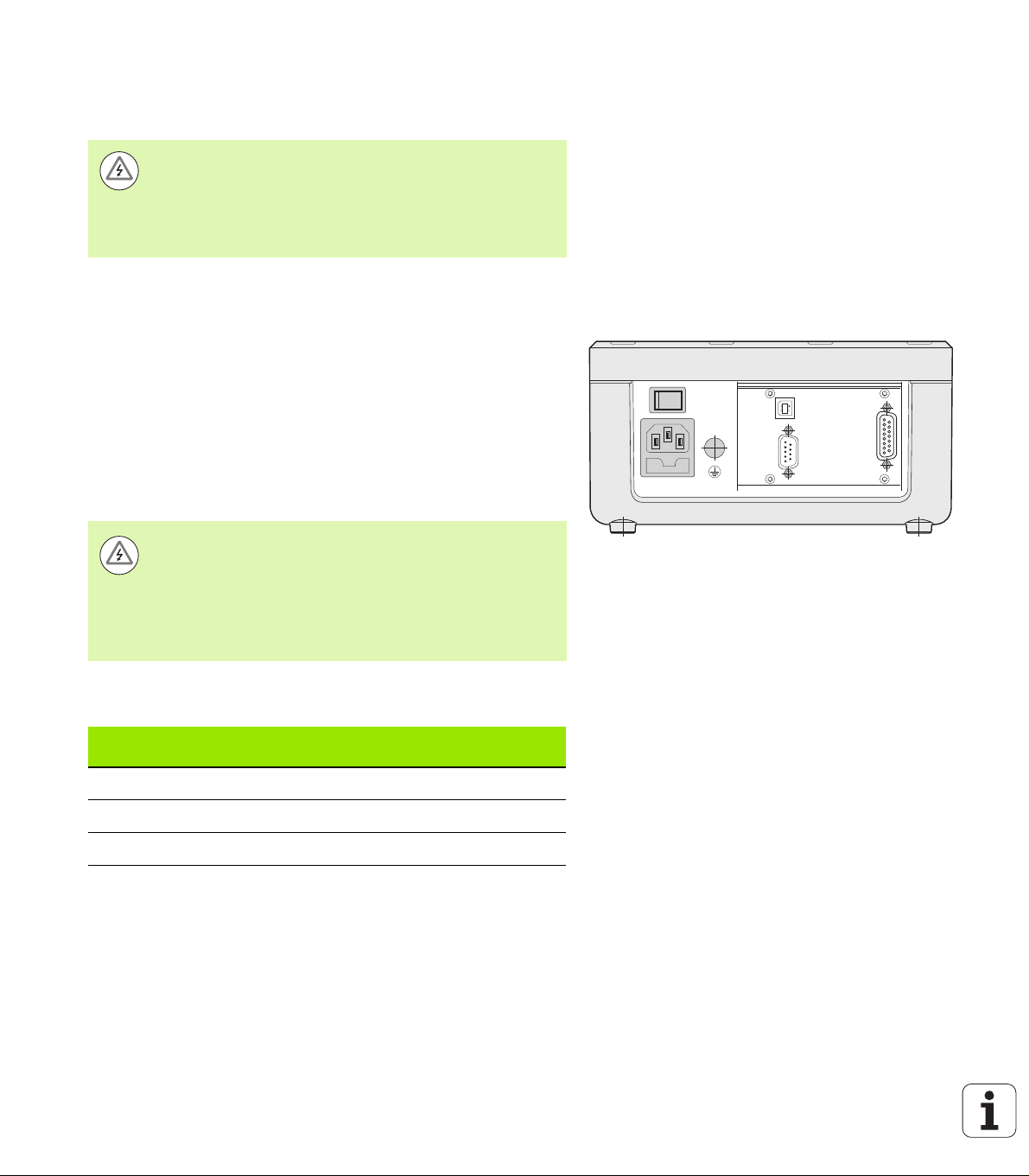
Preventative maintenance or repair
X1
X32/X31
No special preventative maintenance is necessary. For cleaning, wipe
lightly with a dry lint-free cloth.
Danger of electrical shock!
The position display unit must be repaired by qualified
and authorized service technicians.
See the last page of the Operating Instructions for our
service department's contact data.
Connecting the encoders
The ND 287 operates with the following encoders:
Incremental encoders with sinusoidal output signals (11 µApp or
1 Vpp interface)
Absolute encoders with a bidirectional EnDat interface (purely serial;
when an EnDat 2.1 interface is used, the resolution is limited,
because the incremental signals are ignored.)
Optional: Analog sensor with ±10 V interface
The slots for the encoder input assemblies on the rear panel are
designated X1 and X2.
Danger of electrical shock!
The interfaces X1 and (optionally) X2 comply with the
requirements of EN 50 178 for low voltage electrical
II – 1 Installation and electrical connection
separation.
Do not engage or disengage any connecting elements
while the unit is under power!
Fig. II.5 Connections
D-sub connection X1/X2 (15-pin, female) for the following input signals
Input signal
11 µApp 30 m 100 kHz
1 Vpp 60 m 500 kHz
EnDat 100 m -
68 II Installation, specifications
Maximum
cable length
Maximum input
frequency
Page 69

Pin assignment X1/X2
1 8
915
D-sub
connector
15-pin
1I1+ A+
2 0 V (UN) 0 V (UN) 0 V (UN)
3I2+ B+
4 5 V (Up) 5 V (Up) 5 V (Up)
5 Data
6 Internal shield
7I0– R–
8Clock
9I1– A–
10 0 V sensor 0 V sensor
11 I2– B–
12 5 V sensor 5 V sensor
13 Data (inverse)
14 I0+ R+
15 Clock (inverse)
Input signal
11 µAp p
Input signal
1 Vpp
EnDat
(purely serial)
Fig. II.6 15-pin encoder connector X1 or X2 for the
encoder input on the rear panel
II – 1 Installation and electrical connection
Housing External shield External shield External shield
In the INSTALLATION SETUP menu, you define the
parameters for the encoder (see "Setting up the encoder"
on page 71).
Optional: Analog module with ±10 V interface at input X1 or X2 for connecting an analog sensor
For example, you can connect an analog linear encoder to this
connection, or a temperature sensor with a voltage interface to X2.
The ND converts the voltage value to a readable measured value.
A separate description of the analog module is included with the
module.
ND 287 69
Page 70

II – 2 Installation Setup
INSTALLATION SETUP menu
The ND 287 offers two categories for setting up operating parameters:
JOB SETUP and INSTALLATION SETUP.
The JOB SETUP parameters are used to accommodate specific
machining requirements for each job, see "Job Setup" on page 30.
The INSTALLATION SETUP menu is used to establish encoder,
display and communication parameters.
To call the INSTALLATION SETUP menu:
Begin by pressing the SETUP soft key. This opens the JOB SETUP
menu.
Press the INSTALLATION SETUP soft key.
II – 2 Installation Setup
Use the numeric keys to enter the correct passcode (95148) and
then press ENTER.
INSTALLATION SETUP parameters are established during the initial
installation and, most likely, will not often change. For this reason, the
INSTALLATION SETUP parameters are protected by a passcode.
Once you enter the passcode, it will not have to be
entered again until you cycle power.
When in the INSTALLATION SETUP menu, the following soft keys will
be available (see Fig. II.7):
JOB SETUP
Press to begin accessing the JOB SETUP parameters (see "Job
Setup" on page 30).
IMPORT/EXPORT
Press this soft key to call the IMPORT or EXPORT soft keys for
transmitting the operating parameters (see "Serial data transfer with
the Import or Export function" on page 101).
HELP
This soft key will open on-line help.
Press the NAVIGATION key to move through the pages of menu
parameters. To view and change menu parameters, use the UP/
DOWN arrow key to highlight the parameter of interest and press the
ENTER key.
On the following pages you will find more information on the menu
parameters.
Fig. II.7 INSTALLATION SETUP menu
70 II Installation, specifications
Page 71

Setting up the encoder
In the ENCODER SETUP form you configure the ND 287 for the
connected encoder:
The cursor will default to the ENCODER SETUP field upon opening
INSTALLATION SETUP. Press the ENTER key to confirm your
selection.
If you have configured the ND for two axes in the APPLICATION
field under COUNTER SETTINGS, a list of the possible encoder
inputs, labelled INPUT X1 and X2, appears.
Scroll to the input you want to configure and press ENTER.
The cursor will be in the ENCODER TYPE field. Select the encoder
type by pressing the TYPE soft key:
LINEAR: Linear encoder
ROTARY: Rotary encoder
COMPENSATION: If an analog module (option) with a
temperature sensor is connected to input X2, and a linear encoder
to input X1, the COMPENSATION parameter is available for
defining temperature-dependent axis-error compensation.
SENSOR: For inputs with analog module (option) and connected
analog sensor
Press the ENTER key to confirm your selection.
The ND automatically enters the measurement signal received in
the ENCODER SIGNAL field: NO SIGNAL, 1 VPP, 11 µApp,
EnDat 2.1, EnDat 2.2 or ANALOG.
Fig. II.8 Encoder setup form
II – 2 Installation Setup
Fig. II.9 Encoder type
ND 287 71
Page 72

Incremental linear encoder
For linear encoders, cursor to the SIGNAL PERIOD field and toggle
the COARSER or FINER soft key to select a predefined encoder
signal period, or type in the exact signal period (in µm) desired (see
"Encoder parameters" on page 98).
In the REFERENCE MARK field, toggle the REF MARK soft key to
select whether the encoder has no reference signal (NONE), a
single reference mark (SINGLE) or distance-coded reference marks
(CODED/...). For distance-coded reference marks, select the
spacing (500, 1000, 2000 or 5000 signal periods).
In the EXTERNAL REF field, press the ON/OFF soft key to select
whether pin 25 at connection X41 is active or inactive. This pin can
be used to activate or deactivate the reference mode. The
respective current status is changed.
In the COUNT DIRECTION field, select the count direction by
II – 2 Installation Setup
pressing the POSITIVE/ NEGATIVE soft key. If the encoder's count
direction matches the user's traverse direction, select POSITIVE. If
the directions do not match, select NEGATIVE.
In the ERROR MONITOR field, select whether the ND will monitor
and display encoder counting and signal errors by pressing the
ERROR soft key. In the ERROR MONITOR field, you can select OFF,
FREQUENCY, CONTAMINATION or FRQ.+CONTAMINATION.
When an error message occurs, press the C key to acknowledge it.
If you set the ERROR MONITOR field to OFF, the ND 287
will ignore encoder errors.
Fig. II.10 Incremental linear encoder form
Fig. II.11 Incremental linear encoder form
Counting errors are caused by contamination or excessive
frequency:
Contamination: The signal to the encoder falls below a set limit.
Frequency errors: The signal frequency exceeds the set limit.
Fig. II.12 Incremental linear encoder form
72 II Installation, specifications
Page 73

Incremental rotary encoder
For rotary encoders, enter the encoder's signal period per revolution
(360°) directly in the SIGNAL PERIOD field (see "Encoder
parameters" on page 98). Press the DOWN arrow key to move to the
next parameter.
In the REFERENCE MARK field, use the numeric keys to enter the
number of reference marks (0 for NONE, 1 for SINGLE, ...) per
revolution (360°).
In the EXTERNAL REF field, press the ON/OFF soft key to select
whether pin 25 at connection X41 is active or inactive. This pin can
be used to activate or deactivate the reference mode. The
respective current status is changed.
In the COUNT DIRECTION field, select the count direction by
pressing the POSITIVE/ NEGATIVE soft key. If the encoder's count
direction matches the user's traverse direction, select POSITIVE. If
the directions do not match, select NEGATIVE.
In the ERROR MONITOR field, select whether the ND will monitor
and display encoder counting and signal errors by pressing the
ERROR soft key. In the ERROR MONITOR field, you can select OFF,
FREQUENCY, CONTAMINATION or FRQ.+CONTAMINATION.
When an error message occurs, press the C key to acknowledge it.
If you set the ERROR MONITOR field to OFF, the ND 287
will ignore encoder errors.
Fig. II.13 Incremental rotary encoder form
II – 2 Installation Setup
Counting errors are caused by contamination or excessive
frequency:
Contamination: The signal to the encoder falls below a set limit.
Frequency errors: The signal frequency exceeds the set limit.
Fig. II.14 Incremental rotary encoder form
Fig. II.15 Incremental rotary encoder form
ND 287 73
Page 74

Absolute encoder
For absolute encoders with EnDat interface, you can only
define the COUNT DIRECTION and the ERROR
MONITOR.
All other fields in the ENCODER SETUP form show
information that has been transferred from the encoder.
Press the ENDAT ENC. FILE soft key to display the
encoder's electronic ID label. In this form, you can cancel
an existing datum shift by pressing the CANCEL DATUM
SHIFT soft key.
When an EnDat 2.1 interface is used, the resolution is
limited, because the incremental signals are ignored.
II – 2 Installation Setup
Using an absolute multiturn rotary encoder as a linear encoder
Select the multiturn rotary encoder input in the ENCODER SETUP
form and press ENTER to confirm.
Select LINEAR in the ENCODER TYPE field and press ENTER to
confirm your selection.
Enter the ball screw pitch in mm in the SCREW PITCH field and
press ENTER to confirm your entry.
The multiturn rotary encoder will now be handled as if it were an
absolute linear encoder.
Fig. II.16 Absolute encoder form
Fig. II.17 Example of electronic ID label
Fig. II.18 Screw pitch form
74 II Installation, specifications
Page 75

Analog sensor with ±10 V interface, preferably a temperature sensor
In the COUNT DIRECTION field, select the count direction by
pressing the POSITIVE/ NEGATIVE soft key. If the encoder's count
direction matches the user's traverse direction, select POSITIVE. If
the directions do not match, select NEGATIVE.
In the four following fields, enter any two voltage/measured-value
pairs for the correct definition of the analog sensor: At first, enter the
values in the VOLTAGE 1 and MEASURED VALUE 1 fields, and then
in the VOLTAGE 2 and MEASURED VALUE 2 fields. The ND 287
uses the values to calculate a linear relationship between input
voltage and measured value in the range from –10 V to +10 V. To
ensure the highest possible measuring accuracy, enter the voltage
values with an accuracy of 5 mV.
If you have selected COMPENSATION for INPUT X2 in the
ENCODER TYPE field in the ENCODER SETUP menu, two further
parameters for defining temperature-dependent axis-error
compensation are displayed.
In the COEF. OF EXPANSION field, enter a value for the coefficient
of expansion E in µm/mK.
In the REF. TEMPERATURE field, enter the temperature T
to be
R
deducted from the measured temperature.
The axis-error compensation is calculated according to the following
formula:
L_1 = L_0 * (1 + E * (T - TR))
L_1: Compensated linear value of the encoder at input X1 after
axis-error compensation
L_0: Displayed linear value of the encoder at input X1 without
compensation
E: Coefficient of expansion in µm/mK
T: Temperature measured in °C
: Defined reference temperature in °C
T
R
Press ENTER to confirm your entry.
The ND 287 constantly displays the measured temperature on the
left side of the message line.
Fig. II.19 Analog sensor form
II – 2 Installation Setup
Fig. II.20 Analog sensor form
Fig. II.21 Temperature sensor form
ND 287 75
Page 76

Configuring the display
In the DISPLAY CONFIGURATION form you determine the display
resolution for the different encoders.
In the INSTALLATION SETUP menu, select DISPLAY
CONFIGURATION.
If you have configured the ND for two axes in the APPLICATION
field under COUNTER SETTINGS, a list of the possible encoder
inputs, labelled INPUT X1 and X2, appears.
Scroll to the input you want to configure and press ENTER.
The selectable display resolution depends on the signal
period. The smallest selectable display resolution
corresponds to the rounded-off value calculated from
II – 2 Installation Setup
Linear encoder
Press the COARSER or FINER soft key to select the display
resolution for the axis display in the DISPL. RESOLUTION X1 or
X2 field.
Rotary encoder
Press the COARSER or FINER soft key to select the display
resolution for the axis display in the DISPL. RESOLUTION X1 or
X2 field.
In the ANGLE DISPLAY field, press the ANGLE soft key to choose
between the three following angle formats:
+/– 180 DEGREES
360 DEGREES
+/– INFINITE
dividing the signal period by 4096. For linear encoders,
resolutions from 0.5 mm to 0.001 µm are possible, and for
rotary encoders from 0.5° to 0.000001° (00°00'00.1").
Fig. II.22 DISPLAY CONFIGURATION form for linear
encoder
Fig. II.23 DISPLAY CONFIGURATION form for rotary
encoder
Analog sensor for compensation
Press the COARSER or FINER soft key to select the display
resolution for the measured value in the DISPL. RESOLUTION X1 or
X2 field. The minimum resolution depends on the assignment of the
measured values to the voltage values. The ND subdivides the input
voltage range of ±10 V 4096-fold, i.e. in steps of 5 mV.
If two axes are coupled, the finer of the two display
resolutions will be used.
Fig. II.24 DISPLAY CONFIGURATION form for
analog sensor
76 II Installation, specifications
Page 77

Counter settings
In the COUNTER SETTINGS form, you define the user application for
the position display unit (see Fig. II.25):
In the INSTALLATION SETUP menu, select COUNTER SETTINGS.
In the APPLICATION field, press the 1 AXIS/2 AXES soft key to
select the inputs you want to activate:
If the position display unit is configured for 1 AXIS, then only input
X1 is active.
If the position display unit is configured for 2 AXES, inputs X1 and
X2 are active. The ND can display the axis values separately, or as
a coupled position value. After you have selected 2 AXES, the
SOFTKEY X1/X2 and FUNCTION f(X1,X2) soft keys will be
displayed. Press the SOFTKEY X1/X2 soft key to define the
display modes for axes X1 and X2 that can be selected on the
standard screen. Press the FUNCTION f(X1,X2) soft key to enter
a formula for the coupled position display ((see page 78)).
In the KEYBOARD field, use the KEYPAD soft key to release/lock
the keypad. To release the locked keypad, press and hold the
NAVIGATION key for at least three seconds. Then enter the
password (246584) for releasing the keypad and confirm your entry
by pressing the ENTER key, or cancel by pressing the C key.
Press the DOWN arrow key to move to the next parameter.
Press the SECOND DEC. POINT soft key to display a second
decimal point after 1/1000 inches (mm).
Press the POWER UP SCREEN soft key to define whether the ND
displays the initial screen after it has been switched on.
Press the DOWN arrow key to move to the next parameter.
The DISPLAY UNIT field shows the type of position display.
The SOFTWARE VERSION field shows the currently installed
software version and its identification number. To update your
software version, see "Software update (firmware update)
installation" on page 103.
The FACTORY DEFAULTS soft key resets the configuration
parameters to factory defaults. Press the ENTER key to confirm, or
press the C key to cancel.
Fig. II.25 COUNTER SETTINGS form
II – 2 Installation Setup
Fig. II.26 COUNTER SETTINGS form
When a temperature sensor at input X2 is used, the ND
compensates the axis error (see "Analog sensor with
Fig. II.27 COUNTER SETTINGS form
±10 V interface, preferably a temperature sensor" on page
75).
ND 287 77
Page 78

Setting the display modes of the axes
The DISPLAY MODE soft key enables you to scroll through the
available display modes.
Press the SOFTKEY X1/X2 soft key to change the state of the
respective display mode from VISIBLE to HIDDEN, and vice versa.
In the HIDDEN state the respective display mode can no longer be
set with SOFTKEY X1 [X2] on the standard screen.
Press the ENTER key to confirm your settings, or press the C key to
cancel.
Formula for coupled position
II – 2 Installation Setup
In this form, you can enter a formula for coupling the two axes. The
following mathematical operations, symbols and variables are
available:
Basic arithmetic: Addition, subtraction, multiplication and division
Parentheses
Trigonometric functions: Sine, cosine, tangent, arc sine, arc cosine
and arc tangent
Circle constant pi
Axis variables X1 and X2
Enter the desired formula.
If you want to delete a character you have entered, press the DOWN
arrow key.
After you have confirmed your entries by pressing ENTER, the
ND 287 checks the formula for syntax errors, and displays an error
message if the formula is not correct.
Fig. II.28 Form for setting the display modes
Fig. II.29 Formula input form
The ND 287 checks whether all required operators
(e.g. 3X1 must be entered as 3*X1) have been entered,
and whether opening parentheses are followed by
closing parentheses.
Axis values that are used as divisors may cause a
division-by-zero or display-overflow problem. The
ND 287 prevents these errors by displaying the Display
overflow message. After you have removed the
affected axis from the range about zero, the ND 287 will
Fig. II.30 Formula input form
display a correct numerical value again.
The ND 287 cannot check whether the entered formula
is going to produce a meaningful result for you. It is
your responsibility to check this.
78 II Installation, specifications
Page 79

Error compensation
The distance a cutting tool travels, measured by an encoder, can in
certain cases, differ from the actual tool travel. This error can occur
due to ball screw pitch error or deflection and tilting of axes.
This error can either be linear or non-linear. You can determine these
errors with a reference measurement system, e.g. the VM 101 from
HEIDENHAIN. From an analysis of the error it can be determined
which form of compensation is required (linear or non-linear).
The ND 287 can compensate these errors. Each axis can be
programmed separately with the appropriate compensation.
The ND can also compensate errors caused by temperature
influences. A linear encoder must be connected to input X1, and an
analog module (option) with a temperature sensor must be connected
to input X2.
Only non-linear error compensation is available when
using rotary encoders.
II – 2 Installation Setup
ND 287 79
Page 80

Linear error compensation (not for rotary encoders)
LEC
SM–
M
------------------
106× ppm=
LEC
500 499 95,()–
499 95,
------------------------------------------------
106× ppm 100ppm==
Linear error compensation can be applied if the results of the
comparison with a reference standard show a linear deviation over the
whole measuring length. In this case the ND 287 can compensate the
error mathematically by calculating the LEC correction factor.
To calculate the linear correction factor, use the following formula:
S: length measured with reference standard
M: measured length with device at axis
ppm: parts per million
1 ppm = 10
-6
= 1 µm/m = 1 µinch/inch
Example:
II – 2 Installation Setup
If the length of the standard you used is 500 mm and the measured
length along the X axis is 499.95 mm, then the LEC for the X axis is
100 ppm:
Entering linear error compensation
In the INSTALLATION SETUP menu, select ERROR
COMPENSATION.
If you have configured the ND for two axes in the APPLICATION
field under COUNTER SETTINGS, you can define error
compensation for the two possible encoder inputs, labelled INPUT
X1 and X2.
Select the input you want to define.
Press the ERROR COMP. soft key to select the desired type of
compensation.
If you select OFF, no error compensation will be applied.
0.0 PPM: Use the numerical keys to enter the linear correction
factor in ppm.
Fig. II.31 Linear error compensation form
NONLINEAR (see "Non-linear error compensation" on page 81).
If necessary, press the UP/DOWN arrow key to select the next
input, and define the error compensation for this input.
Press ENTER to confirm your entries.
80 II Installation, specifications
Page 81

Non-linear error compensation
Non-linear error compensation is available for encoders
with reference marks, for absolute encoders and for
analog sensors.
If non-linear error compensation has been defined, no
error compensation will be applied until the reference
marks have been crossed.
Non-linear error compensation should be applied if the results of the
comparison with a reference standard show an alternating or
oscillating deviation. The ND 287 supports up to 200 correction
points per axis. The error value between two entered adjacent
correction points is calculated with linear interpolation. The required
correction values must be calculated and entered in an error
compensation table.
For rotary encoders, 180 correction points spaced every 2° are
predefined by the ND 287.
Selecting non-linear error compensation
In the INSTALLATION SETUP menu, select ERROR
COMPENSATION.
If you have configured the ND for two axes in the APPLICATION
field under COUNTER SETTINGS, you can define error
compensation for the two possible encoder inputs, labelled INPUT
X1 and X2.
Select the input you want to define.
Press the ERROR COMP. soft key to select NON-LINEAR.
II – 2 Installation Setup
Fig. II.32 Non-linear error compensation form
ND 287 81
Page 82

Creating an error compensation table
To start a new error compensation table, first press the EDIT TABLE
soft key. This opens the ERROR COMPENSATION TABLE form.
It may occur that the error is not caused by the axis to be
compensated. Press the X1/X2 soft key to select the appropriate
axis in the ERROR-CAUSING AXIS field.
All correction points (up to 200) are equally spaced from the start
point. Enter the distance between each of the correction points.
Select POINT SPACING and press the SPACING soft key or the
ENTER key. Enter a value and press ENTER.
Enter the START point:
If the start point is known, enter the start point. Select START
POINT and press the START POINT soft key or the ENTER key.
The start point is measured from the scale's reference point.
II – 2 Installation Setup
If the start point is not known, move to the location of the start
point. Please keep in mind that the reference marks must have
been crossed. Press the TEACH POSITION soft key. Press the
ENTER key to confirm the position.
In the REF DISPLAY field, the ND shows the current value of the
axis to be compensated without considering the datums entered.
After a new start point has been entered, the ND 287 will
adjust the previous values in the error compensation table.
Fig. II.33 Error compensation table
Fig. II.34 Error compensation table
Fig. II.35 Error compensation table: Enter the START
point.
82 II Installation, specifications
Page 83

Configuring an error compensation table
Press the EDIT TABLE soft key to view the table entries.
Use the UP/DOWN arrow key or the numeric keys to move the
cursor to the correction point to be added or changed. Press ENTER
to confirm your selection.
Enter the known error which exists at this point. Confirm with the
ENTER key.
When completed, press the C key to exit the table and return to the
ERROR COMPENSATION form.
Reading the graph
The ND 287 can display the error compensation table in table or
graphical format. The graph shows a plot of a translation error vs.
measured value. The graph has a fixed scale.
Viewing the error compensation table
Press the EDIT TABLE soft key.
Press the UP/DOWN arrow key or the numeric keys to move the
cursor within the table.
To switch between the table and graph views, press the VIEW soft
key.
Use the ZOOM IN or ZOOM OUT soft key to enlarge or reduce to
graphic to 20 and 200 points, respectively. The enlarged graphic
display can be scrolled forward or backward by 20 points by pressing
the ⇐ and soft key.
Fig. II.36 Editing an error compensation table
II – 2 Installation Setup
Fig. II.37 Entering the error determined for the
measured value
Fig. II.38 Graphic representation of compensation
values
ND 287 83
Page 84

The error compensation table data may be saved to or loaded from a
PC via the serial port (see "Setting up the serial port" on page 85).
Exporting the current compensation table
Press the EDIT TABLE soft key.
Press the IMPORT/EXPORT soft key.
Press the EXPORT TABLE soft key.
Importing a new error compensation table
Press the EDIT TABLE soft key.
Press the IMPORT/EXPORT soft key.
Press the IMPORT TABLE soft key.
Press the IMPORT READY soft key.
II – 2 Installation Setup
Fig. II.39 Importing or exporting compensation
values
Fig. II.40 Importing compensation values
84 II Installation, specifications
Page 85

Setting up the serial port
X1
X32/X31
The ND 287 features two serial interfaces: RS-232-C/V.24 (X31) and
USB (UART, X32).
Danger of electrical shock!
The interfaces X31 and X32 comply with the requirements
of EN 50 178 for low voltage electrical separation.
Do not engage or disengage any connecting elements
while the unit is under power!
A printer or computer with a serial data interface may be connected to
the available serial ports in order to perform the following tasks:
Sending measured values, error compensation tables or
configuration files to a printer or computer.
Receiving error compensation tables or configuration files from a
computer.
In addition, the interfaces allow external operation of the ND 287.
As an option, an Ethernet module (100baseT) can be connected to
X26/X27 so that an Ethernet interface is available.
Setting up the data interface
In the INSTALLATION SETUP menu, select INTERFACE SETTINGS.
In the SERIAL PORT field, use the USB/RS-232 soft key to select the
interface you want to use.
The BAUD RATE field can be set to 110, 150, 300, 600, 1200, 2400,
9600, 19200, 38400, 57600 or 115200 by using the DECREASE or
INCREASE soft keys.
Fig. II.41 Connections
II – 2 Installation Setup
Fig. II.42 RS-232-C/V.24 data interface
Fig. II.43 USB (UART) data interface
ND 287 85
Page 86
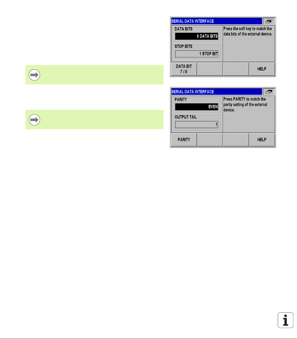
Press the 7/8 soft key to set the DATA BITS field to 7 or 8.
Press the 1/2 soft key to set the STOP BITS field to 1 or 2:
The PARITY field can be set to NONE, EVEN or ODD using the soft
keys provided.
OUTPUT TAIL is the number of carriage returns that will be sent at
the end of the transmission. The output tail is initially 0 and can be
set to a positive integer value between 0 and 99 by using the
numerical keys.
There is no parameter to enable or disable the serial ports.
Data will only be sent to the serial port if the external
device is ready.
For information about the cable connection, pin assignment, data
input/output and external operation, see "Data interface" on page 100.
II – 2 Installation Setup
The serial port settings will be retained on a power cycle.
Data is transferred in the following sequence: Start bit,
data bits, parity bit, stop bits.
Fig. II.44 Data interface: Parameter input
Fig. II.45 Data interface: Parameter input
86 II Installation, specifications
Page 87

Diagnostics
The DIAGNOSTICS submenu provides parameters for testing the
keypad, the LCD display, the connected encoders, the supply
voltages, and the function of the switching inputs/outputs (see Fig.
II.46):
In the INSTALLATION SETUP menu, select DIAGNOSTICS.
Select the desired test. The tests are described in the following
sections.
Keypad test
An image of the keypad of the ND287 provides an indication when a
key is pressed and released.
Press each hard and soft key to test. A dot will appear on each key
when it has been pressed indicating that it is operating properly.
Press the C hard key twice to exit the keypad test.
II – 2 Installation Setup
Display test
LCD display test:
To test the LCD display, press the ENTER key four times to set the
LCD display to black with white inside, white with black inside, redgreen-blue and back to normal.
Fig. II.46 Diagnostics menu
Fig. II.47 Keypad test
Fig. II.48 Display test
ND 287 87
Page 88

Encoder test
Use this test to check the signals of the 11 µApp or 1 Vpp interface,
the EnDat interface or the voltage at the analog module.
If you have configured the ND for two axes in the APPLICATION
field under COUNTER SETTINGS, you can perform the test for the
two possible encoder inputs.
Select input X1 or X2 and press ENTER.
Encoders with 11 µApp or 1 Vpp interface:
As the encoder is moved, you will see the signals of the A and B
channels as Lissajous figure (see Fig. II.49), as well as the
amplitude, symmetry and phase offset values.
II – 2 Installation Setup
Fig. II.49 Encoder test: 1 Vpp interface
Fig. II.50 Encoder test: 11 µApp interface
88 II Installation, specifications
Page 89

Encoders with EnDat interface:
The form displays the electronic ID label of the connected encoder:
Transmission format, signal periods, measuring steps,
distinguishable revolutions, ID number and serial number.
Only for encoders with EnDat 2.2 interface: The DIAGNOSIS soft
key opens a form showing the function reserve of the encoder:
Incremental track (INC)
Absolute track (ABS)
Position value calculation
Press the ALARMS soft key to display the alarms that are supported
by the connected encoder, and to show whether errors have
occurred. A color-filled square before the respective alarm indicates
the status:
Gray means that the alarm is not supported by the connected
encoder.
Green means that the alarm is supported by the connected
encoder, and no error has occurred yet.
Red signalizes that an error has occurred.
Press the WARNINGS soft key to display the warnings that are
supported by the connected encoder, and to check whether
warnings have occurred. A color-filled square before the respective
warning indicates the status:
Gray means that the warning is not supported by the connected
encoder.
Green means that the warning is supported by the connected
encoder, and no warning has occurred yet.
Red signalizes that a warning has occurred.
To clear alarms or warnings that have occurred, press the RESET
soft key when the ALARMS or WARNINGS window is open.
Fig. II.51 Encoder test:
EnDat interface
II – 2 Installation Setup
Fig. II.52 Encoder test:
EnDat 2.2 interface
Fig. II.53 Encoder test:
EnDat interface
ND 287 89
Page 90

Analog sensors with ±10 V interface:
In the form, the voltage at the input of the analog module is
displayed as a numerical value and in a bar graph.
Power supply
Check the supply voltage at encoder inputs X1 and X2 (optional). It
should normally be slightly above 5 V in order to ensure that the
voltage level at the encoder input complies with the specification (5 V
± 5%) even at greater cable lengths.
II – 2 Installation Setup
Fig. II.54 Encoder test: Analog sensor
Fig. II.55 Power supply
90 II Installation, specifications
Page 91

Switching inputs test
Danger to internal components!
The power supply of external circuits must comply with
EN 50178 requirements for low voltage electrical
separation.
Connect inductive loads only with a quenching diode
parallel to the inductance.
Danger to internal components!
Use only shielded cables and connect the shield to the
connector housing.
The ND displays a list with all switching inputs at the D-sub connection
X41 (see "Switching inputs at D-sub connection X41" on page 93). The
pins are listed together with their designations, a gray/green dot and
their current states (HIGH or LOW). The function of the inputs at
connection X41 can be tested:
As soon as a pin has been activated (=LOW), the gray dot next to
the respective pin designation becomes green and the status
changes to LOW if the input functions correctly.
II – 2 Installation Setup
Fig. II.56 Switching inputs test
ND 287 91
Page 92

Switching outputs test
Danger to internal components!
The power supply of external circuits must comply with
EN 50178 requirements for low voltage electrical
separation.
Connect inductive loads only with a quenching diode
parallel to the inductance.
Danger to internal components!
Use only shielded cables and connect the shield to the
connector housing.
The ND 287 displays all switching outputs at connection X41
II – 2 Installation Setup
together with their designations, a gray/green dot and their current
states (HIGH or LOW; see "Switching outputs at D-sub connection
X41" on page 95). To start the switching outputs test:
Press the CYCLIC TEST soft key to activate (= LOW, open collector)
all outputs successively for 1 second.
To exit the cyclic test, press the CURRENT STATE soft key or
the C hard key.
Fig. II.57 Switching outputs test
92 II Installation, specifications
Page 93

II – 3 Switching inputs and outputs
X1
X32/X31
Switching inputs at D-sub connection X41
Danger to internal components!
The power supply of external circuits must comply with
EN 50178 requirements for low voltage electrical
separation.
Connect inductive loads only with a quenching diode
parallel to the inductance.
Danger to internal components!
Use only shielded cables and connect the shield to the
connector housing.
Pin Function See page
1, 10 0 V
Fig. II.58 Connections
2 Reset to zero, clear error message Page 31
3 Set axis / coupled axes to value for datum point
4 Ignore reference mark signals (X1) Page 94
5 Start series of measurements / f(X1,X2) display Page 40
6 Externally select display value for series of measurements / X1 display
7 Display minimum value of series of measurements / X2 display
8 Display maximum value of series of measurements / X1+X2 display
9 Display difference MAX-MIN of series of measurements / X1-X2 display
22 Pulse: Transmit measured value Page 94 and
Page 44
23 Contact: Transmit measured value
24 Ignore reference mark signals (X2, optional) Page 94
25 Enable or disable REF mode (current REF status is changed) Page 22
12, 13 Do not assign
11, 20, 21 Vacant
II – 3 Switching inputs and outputs
ND 287 93
Page 94

Special case:
111
2
If you want to display the current measured value ACTL
of a measurement series, the following applies for inputs
7, 8 and 9: Either none or more than one of these inputs
must be active.
Input signals
Signal Va lu e
Internal pull-up resistor 1 kΩ, active Low
Activation Trigger by making contact
Delay time for preset/reset t
Minimum pulse duration for all
signals (except for pin 22 and
pin 23, see Page 113)
Signal level of inputs
II – 3 Switching inputs and outputs
Status Level
High +3.9 V ≤ U ≤ +15 V
Low –0.5 V ≤ U ≤ +0.9 V; I ≤ 6 mA
Ignoring the reference mark signals
If the input at pin 4 is active, the ND will ignore the reference mark
signals of axis X1. If the input at pin 24 is active, the ND will ignore
the reference mark signals of axis X2 (optional). A typical application
of this function is for measuring lengths with a rotary encoder and
leadscrew; in this case, a cam switch releases the reference mark
signal at a preset position.
against 0 V or by low-level signal
over TTL logic device (see
"Measured value output after a
trigger signal" on page 113)
≤ 2ms
V
t
≥ 30 ms
min
Fig. II.59 Switching inputs for measured value
output at X41; 1: Contact (pin 23), 2:
Pulse (pin 22)
94 II Installation, specifications
Page 95

Switching outputs at D-sub connection X41
Danger to internal components!
The power supply of external circuits must comply with
EN 50178 requirements for low voltage electrical
separation.
Connect inductive loads only with a quenching diode
parallel to the inductance.
Danger to internal components!
Use only shielded cables and connect the shield to the
connector housing.
Pin Function
14 Display value is zero
15 Measured value is greater than or equal to trigger limit A1
16 Measured value is greater than or equal to trigger limit A2
17 Measured value is less than the lower sorting limit
18 Measured value is greater than the upper sorting limit
19 Error (see "Error messages" on page 60)
Output signals
Signal Va lue
Open-collector outputs Active Low
Delay until signal output t
Signal duration of zero
crossover, trigger limit A1, A2
Signal level of outputs
Status Level
High U ≤ +32 V; I ≤ 10 µA
Low U ≤ +0.4 V; I ≤ 100 mA
≤ 20 ms
V
t
≥ 180 ms
0
II – 3 Switching inputs and outputs
Fig. II.60 Open-collector outputs
ND 287 95
Page 96

Trigger limits
111
2
1
3
-10
s
t
t
v
2
t
v
1
Pin 15
(A1)
100
As soon as the trigger limit 1 defined by parameter is reached (see
figure at right), the corresponding output 2 is activated (3: path). You
can set up to two trigger limits: A1 and A2 (see "Switching signals" on
page 38). A separate output is available for the zero crossover (see
"Zero crossover" on page 97).
In the Distance-To-Go operating mode, switching outputs A1 (pin 15)
and A2 (pin 16) have a different function: They are symmetrical about
zero. For example, if a trigger point of 10 mm is entered for A1, then
output A1 switches at both +10 mm and -10 mm. Fig. II.62 shows
output signal A1 when traversing to display value zero from the
negative direction: A1 = 10 mm, tV1≤ 30 ms, tV2≤ 180 ms.
II – 3 Switching inputs and outputs
Fig. II.61 Trigger limit A1
Fig. II.62 Time curve of signal at pin 15 for trigger
limit A1 = 10 mm
96 II Installation, specifications
Page 97
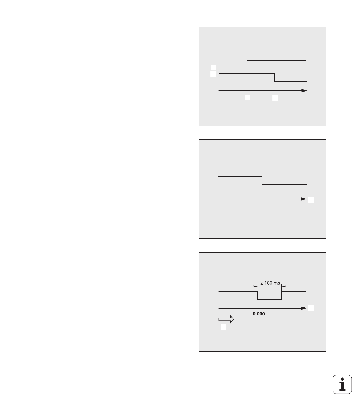
Sorting limits
1
1
12131
4
ERROR xx
15161
7
If the measured value exceeds the sorting limits, the ND activates the
outputs at pin 17 or pin 18 (see "Sorting and tolerance checking" on
page 58).
Example: See figure at upper right.
1: Lower limit
2: Upper limit
3: Measured value < Lower sorting limit
4: Measured value > Upper sorting limit
Trigger signal for error
The ND constantly monitors the measuring signal, the input
frequency, the data output, etc., and displays an error message if it
detects an error. If errors occur that seriously influence measurement
or data output, the ND activates the output at pin 19. This feature
allows monitoring of automated processes.
Zero crossover
If the display value is zero, the ND activates the output at pin 14. The
minimum signal duration is 180 ms.
Fig. II.63 Sorting limits
II – 3 Switching inputs and outputs
Fig. II.64 Trigger signal for error 5: Time
Fig. II.65 Zero crossover; 6: Direction of traverse; 7:
ND 287 97
Path
Page 98

II – 4 Encoder parameters
Table values
The following tables represent a partial list of HEIDENHAIN encoders.
These tables describe the operating parameters which you must set
for the encoders. Most entries can be found in the operating
instructions for your encoder.
HEIDENHAIN linear encoders
Encoder Signal period Reference marks
SPECTO ST 12/30 20 µm Single
METRO MT 60/101 10 µm Single
II – 4 Encoder parameters
METRO MT 12xx/25xx 2 µm Single
CERTO CT 25xx/60xx 2 µm Single
LS 388C 20 µm Coded/1000
LS 487
LS 487C
LS 186
LS 186C
LF 183
LF 183C
LB 382
LB 382C
LC 183
LC 483
LIDA 18x
LIDA 48x
LIDA 28x 200 µm Single
LIDA 583 20 µm Single
LIF 181R
LIF 181C
LIF 581R
LIF 581C
20 µm Single
Coded/1000
20 µm Single
Coded/1000
4 µm Single
Coded/5000
40 µm Single
Coded/2000
Self-configuring None
Absolute
40 µm Single
8 µm Single
Coded/5000
8 µm Single
Coded/5000
98 II Installation, specifications
Page 99

HEIDENHAIN rotary encoders
Encoder Signal period Reference marks
ROD 48x
ERN x80
1000 ... 5000 Single
ROC 425
ECN x25
ROQ 437
EQN 437
ROD 280
ROD 280C
RON 28x
RON 28xC
RON 785
RON 785C
RON 886
RON 886C
RCN 22x Self-configuring None
RCN 729
RCN 829
Self-configuring None
Absolute
Self-configuring None
Absolute
18000 Single
Coded/36
18000 Single
Coded/36
18000 Single
Coded/36
36000 Single
Coded/72
Absolute
Self-configuring None
Absolute
II – 4 Encoder parameters
ND 287 99
Page 100

II – 5 Data interface
V.24/RS-232-C
Data communication
The ND 287 features two serial interfaces: RS-232/V.24 (X31) and
USB (UART, X32).
Danger to internal components!
The interfaces X31 and X32 comply with the requirements
of EN 50 178 for low voltage electrical separation.
II – 5 Data interface
The serial ports support both bi-directional data communication, which
allows data to be exported to or imported from an external device, and
external operation of the ND 287 via the data interface.
Data which can be exported from the ND 287 to an external serial
device includes:
Job and installation configuration parameters
Non-linear error compensation tables
Measured value output
Data which can be imported into ND 287 from an external device
includes:
Key commands
Job and installation configuration parameters
Non-linear error compensation tables
Software updates (firmware update)
This chapter covers what you need to know about setting up the data
interface:
Serial data transfer with the Import or Export function
Software update (firmware update) installation
Wiring of the connecting cable at the ND 287
External operation
Do not engage or disengage any connecting elements
while the unit is under power!
As an option, an Ethernet module (100baseT) can be
connected to X26/X27 so that an Ethernet interface is
available to connect the ND to a network via the TCP/IP
protocol.
Fig. II.66 Data communication via RS-232-C/V.24
100 II Installation, specifications
 Loading...