

Page 1
HEIDENHAIN
Working with the position
display unit
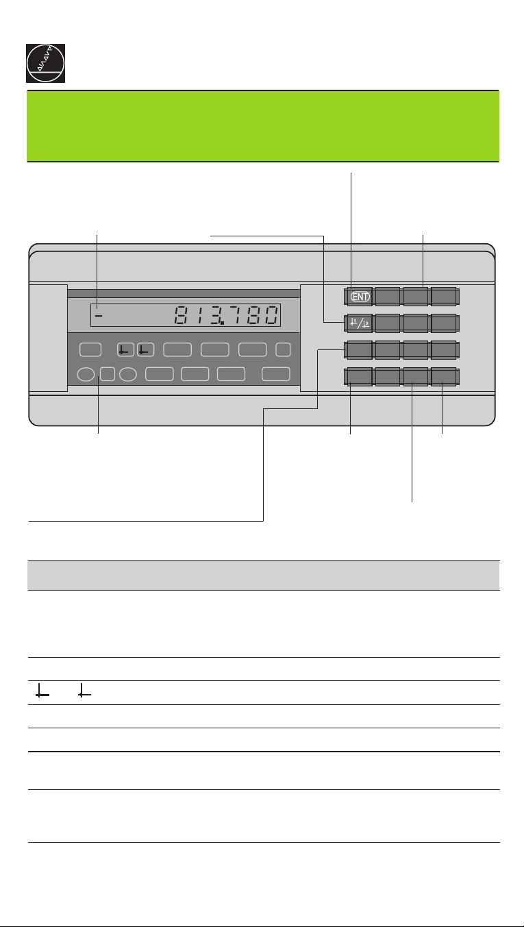
Actual value and input display
(7-segment LED,
9 decades and sign)
• Select datum
• Page backward in
parameter list
ND 286
• Confirm entry value
• Set display to value from
P79 (P80!)
Numeric keypad
789
456
REF21 SET
=
<>
MIN ACTL MAX DIFF
START PRINT
in.
MOD
HEIDENHAIN
Status display
• Switch display to:
MIN / MAX / DIFF / ACTL / START / PRINT
• Go to parameter list after switch-on
• Page forward in parameter list
Indicator Meaning
REF If the decimal points have stopped blinking:
Reference mark was crossed over — datum points are now stored
in nonvolatile memory.
Blinking: Waiting for operator to press ENT or CL.
in. Position values displayed in inches.
1 / 2 Datum 1 / Datum 2 currently active.
PRINT Blinking: Waiting for ENT for data output.
SET Blinking: Waiting for operator to confirm entry.
• Clear entry
• Reset to zero (P80!)
• CL plus MOD:
parameter list
• CL plus 2-digit number: select parameter
• Clear parameter entry
and show parameter
number
123
.
0
–CL
• Algebraic
sign
• Decrease
parameter
value
• Decimal point
• Increase parameter value
< / = / > Sorting mode: Measured value less than lower limit / within
tolerances / greater than upper limit.
MIN / MAX Measuring series: Minimum / Maximum /
DIFF / ACTL largest difference (MAX–MIN) / current measured value.
Blinking: Waiting for confirmation of value to be displayed.
START Measuring series in progress.
Blinking: Waiting for start signal for measuring series.
Page 2
The ND 286 position display unit is designed for use with HEIDENHAIN linear or
rotary encoders with square-wave output signals. These encoders have one or more
reference marks, which may also be
When a reference mark is crossed over, it generates a signal identifying that position
as a reference point. After switch-on, simply crossing over the reference mark
restores the relationship between axis positions and display values as it was last
defined by datum setting.
With distance-coded reference marks, a maximum traverse of only 20 mm suffices to
re-establish the datum.
distance-coded
.
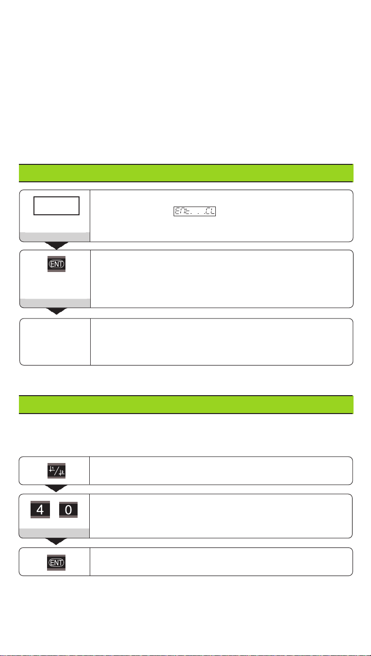
Switch-On
0 ➤1
Ent...CL
5 , 6 9 7
If you do not wish reference mark evaluation, press CL instead of ENT.
Turn on the power (switch located on rear panel).
• Display shows .
• REF indicator blinks.
• Data interface shows ERROR 07
Switch on reference mark evaluation.
• Display shows the value last assigned to the
reference mark position.
• REF indicator glows.
• Decimal point blinks.
Cross over reference mark.
Move the axis until the display becomes active and the
decimal point no longer blinks.
Setting the Datum
The datum setting procedure assigns a display value to a specific axis position.
The ND 286 allows you to set two independent datums.
Select datum 1 or 2.
Enter a value, such as 40.
4 0
Confirm entered value.
You can switch from one datum to the other at any time.
Use datum 2 when you want to display incremental values.
Page 3

Measuring Series
The ND 282 display unit can calculate and display one of the following values from a
measuring series:
Smallest value (MIN), largest value (MAX), difference between largest and smallest
value (DIFF), last value measured (ACTL)
A new value is captured every 550 µs during a measuring series.
To start a measuring series:
➤ Press the MOD key repeatedly until the desired indicator starts blinking.
Example: to display the largest value, press MOD until MAX blinks.
➤ Confirm your selection by pressing ENT.
➤ Press MOD repeatedly until the START indicator blinks.
➤ Start the measuring series by pressing ENT.
You can switch between MIN, MAX, DIFF and ACTL at any time:
➤ Press MOD until the desired indicator blinks, then confirm with ENT. Or
➤ Use operating parameter P21 (see list of operating parameters).
Note:
When the switching input for remote control of the measuring series is active (pin 6
of D-sub connection EXT), you cannot switch over the display as described here.
To abort a measuring series and restart:
➤ Press MOD until START blinks, then confirm with ENT.
To end a measuring series:
➤ Press MOD until the glowing indicator blinks, then confirm with ENT.
It is also possible to start a measuring series and switch over the display with a
switching input over the D-sub connection EXT (see that section).
Sorting and Tolerance Check Mode
In this mode, the display value is compared with an upper and a lower limit value.
Status indicators and the switching outputs at the D-sub connection EXT indicate
whether the display value is less than the lower limit, greater than the upper limit, or
between the two limit values.
Indicator Meaning
= Measured value is between the limit values
< Measured value is less than the lower limit value
> Measured value is greater than the upper limit value
Operating parameters for the sorting mode:
• P17: sorting on / off, P18, P19: limit values
Distance-to-go Mode
The standard setting for the display unit is to show the encoder position value.
Code number 246 582 provides access to the distance-to-go mode.
“Traverse to zero” with distance-to-go display
➤ Select datum 2.
➤ Enter the nominal position.
➤ Move the axis to the display value zero.
In distance-to-go mode the trigger outputs A1 (Pin 15) and A2 (Pin 16) change their
meaning: they become symmetrical to the display value zero.
Page 4

Data Output
There are four ways to output data:
➤ Press the MOD key until the PRINT indicator starts blinking (only possible with
"slow" data output), and start data output with the ENT key; or
➤ Send measuring data to the data output periodically; or
➤ Input a latch command over the D-sub connection EXT; or
➤ Input a latch command over the BCD connection.
Interface mode (see operating parameter P53)
Slow: Output display values
Fast: Output instantaneous values referenced to datum 1
(MIN/MAX/DIFF display values are not output)
A connecting cable (to a PC, for example) is available from HEIDENHAIN
(Id.-Nr. 206 420 ..); cable length up to 10 m (32.8 ft).
Operating parameters
“ AMP-CHAMP“ connection (36-pin, female)
Pins Assignment Pins Assignment
021
2
222
1234 Decade 1 33 Sign
5678 Decade 2 34 Ready
9 10 11 12 Decade 3 35 Meas. val. output
13 14 15 16 Decade 4 36 0V
17 18 19 20 Decade 5
21 22 23 24 Decade 6
25 26 27 28 Decade 7
29 30 31 32 Decade 8
for data output: P23, P53 to P57
3
Output levels Low: U ≤ 0.4 V with I ≤ 6 mA High: U ≥ 3.8 V with I ≤ 2.6 mA
The output signals are TTL-compatible.
Latch levels Low: U ≤ 0.9 V with I
≤ 6 mA High: U ≥ 3.9 V; or
max
TTL levels (internal 10 kΩ pull-up resistor).
Signal transit times
The following table lists approximate signal transit times. If you use the slow
data output and run functions such as measuring series or inch display at the
same time, the actual transit times can be twice as long as those listed here.
Concurrent data output (P55 )
Mode P53 Latch time Data output after
Fast P54 Value from P54 / 2
Slow t ≤ 30 ms t ≤ 8 ms
Data output after external latch (P55 or )
Mode P53 Min. pulse duration Measured value stored after
Pulse / BCD Contact BCD Pulse Contact
Fast 3 µs 7 ms 0.3 µs 1.1 µs 4.8 ms
Slow t ≥ 8 ms t ≥ 13 ms 0.3 µs 1.1 µs 4.8 ms
Data output Latch again after
Pulse/BCD Contact
Fast ≤ 0.3 µs after internal latching 3 µs 7 ms
Slow ≤ 7.5 ms after internal latching 3 µs 7 ms
Page 5

D-Sub Connection EXT (25-pin, male)
Danger to internal components!
Voltage sources for external circuitry must conform to the recommendations in
EN 50 178 for low-voltage electrical separation. Connect inductive loads only
with a quenching diode parallel to the inductance.
Use only shielded cable!
Connect the shield to the connector housing.
Pin Function Pin Function
15 Meas. value ≥ trigger limit A1 (P62) 1 0 V
16 Meas. value ≥ trigger limit A2 (P63) 10 0 V
17 Meas. value < lower sorting limit (P18) 12 Do not assign
18 Meas. value > upper sorting limit (P19) 13 Do not assign
19 Error (see
OutputsInputs
14 Display value is zero 20 Vacant
2 Reset display to zero, clear error message 21 Vacant
3 Preset display to value from P79
25 Cross over reference marks
4 Ignore reference mark signals
5 Start measuring series
6 Remote selection of display val. f. meas. ser.
7 Display minimum value from meas. series
8 Display maximum value from meas. series
9 Display MAX – MIN diff. from meas. series
22 Pulse: output measured value
23 Contact: output measured value
24 Deactivate BCD data output
Error Messages
) 11 Vacant
Display current measured value (ACTL):
Inputs 7, 8 and 9 are
not active, or more
than one of these
inputs is active
Signal levels Low High
Inputs –0.5 V ≤ U ≤ 0.9 V I ≤ 6 mA 3.9 V ≤ U ≤ 15 V
Outputs U ≤ 0.4 V I ≤ 100 mA U ≤ 32 V I ≤ 10 µA
Description of input and output signals
Input signals • Triggering by make contact against 0 V or
• Low level over TTL component
• Internal pull-up resistor 1 kΩ
• Min. pulse duration: t ≥ 30 ms, for fast reset/preset: t ≥ 30 µs
• Min. pulse interval: t ≥ 30 ms, for reset/preset: t ≥ 1,5 ms;
for fast reset/preset: t ≥ 30 µs
• Delay for zero reset/preset: fast data output t
• slow data output t
≤ 2 ms
d
Output signals • Open collector outputs,
active Low
• Signal output delay: t
d
• Zero crossover signal
minimum duration, trigger
output A1, A2: t
Note that these times increase if additional
features are active (such as sorting).
≥ 180 ms
0
≤ 8 ms
C
B
U
CE
E
Pin 1.10
≤ 25 µs;
d
I ≤ 100 mA
+ UB ≤ 32 V
0 V
Page 6

Data Output and Display Freeze by Output Signal
The effect of a signal for measured value output is defined in operating parameter
P55.
➤ Concurrent display: No output value freeze. The output describes the current
measured value ( ).
➤ Frozen display: The output value is frozen and is updated with each signal for
measured value output ( ).
➤ Frozen/concurrent display: The output value freezes only as long as the signal is
present ( ).
P23 defines whether the display shows the current measured value ( ) or the
value at the data output ( ).
Error Messages
To clear error message :
When you have removed the cause of the error,
➤ press CL.
Message Cause and Effect
Last measured value not yet latched
Attempt to reset to zero or preset not permissible.
The display is not reset or preset.
Incorrect input value
Overflow caused by external preset
Value entered cannot be displayed
Overflow, trigger limit 1
Overflow, trigger limit 2
Overflow, lower sorting limit
Overflow, upper sorting limit
Encoder signal too weak1) (encoder may be contaminated)
Input frequency too high for encoder input
(will occur for example when traverse speed too high)
Internal counter overflow
1)
Error while crossing over reference marks
To clear the error message: Switch off the display unit.
Should any of these error codes recur, contact your HEIDENHAIN
service agency.
1)
1)
1)
Erase the operating parameters.
If all decimal points light up, the measured value is too large or too small.
In this case, set a new datum or retract.
If all sorting indicators light up, this means that the upper sorting limit is less than
the lower limit.
1)
These errors are significant for a connected device. The error signal (pin 19) at the
D-sub connection EXT is active.
Page 7

Operating Parameters
The parameters are divided into “user parameters“ and “protected operating
parameters," which can only be accessed by entering a code number.
User parameters
User parameters are operating parameters that you can change without entering the
code number: They are designated P00 to P30, P79, P86
Calling user parameters
To call user parameters immediately after switch-on:
➤➤
➤ Press the MOD key as long as is visible in the display.
➤➤
To call user parameters during operation:
➤➤
➤ Press and hold the CL key, then press MOD.
➤➤
To go directly to a specific user parameter:
➤➤
➤ Press and hold the CL key, then press the first digit of the parameter number.
➤➤
➤➤
➤ Release both keys and press the second digit.
➤➤
Protected operating parameters
Before you can change protected operating parameters you must enter the code
number 95 148 through : They remain accessible until you switch off
the position display.
To page through the parameter list
➤➤
➤ Forward paging: Press the MOD key.
➤➤
➤➤
➤ Backward paging: Press the 1 / 2 key.
➤➤
By paging on, you automatically enter any change you've made in a parameter.
To change operating parameters
➤➤
➤ Increase the parameter value with the decimal point key, or
➤➤
➤➤
➤ Decrease the parameter value with the minus key, or
➤➤
➤➤
➤ Enter the numerical value for the operating parameter, e.g. for P79 ( SET blinks).
➤➤
To correct your entries and show the parameter designation
➤➤
➤ Press the CL key.
➤➤
To exit the operating parameters
➤➤
➤ Press ENT. All changes made become effective.
➤➤
Operating Parameter List
Parameter Meaning Function / Effect Setting
To change a protected operating parameter, enter code
number 95 148.
Unit of Display in millimeters
measurement Display in inches
Sorting mode Sorting on
Classification
Storage
Display
Direction
Lower sorting limit (ensure that P18 < P19)
Upper sorting limit
Value displayed for MIN ACTL MAX DIFF
measuring series
Display value Measured value (
Counting Normal (
direction Inverse (
Sorting off
(ensure that P19 > P18)
Actual
)
Value at data output
Positive
NegNeg
Negative
NegNeg
)
)
Page 8

Parameter Meaning Function / Effect Setting
Subdivision of encoder signals
Subdivision
Decimal point
Encoder
Preset
Message
4, 2, 1, 0.8, 0.5, 0.4, 0.2, 0.1
Counting 0-1-2-3-4-5-6-7-8-9-0
mode 0-2-4-6-8-0
0-5-0
External Interpolation of Encoder Signals
1, 5, 10, 20, 50
Places after decimal 1 / 2 / 3 / 4 / 5 (up to 7 with inch display)
Reference One reference mark
marks Distance-coded with 500 • SP
Reference mark Evaluation
evaluation No evaluation
Encoder No monitoring (
monitoring Contamination
Speed of Slow
data output Fast, storage rate: P54
Latch speed 0.2 / 0.4 / 0.8 / 1.6 / 3.2 / 6.4 / 12.8 / 25.6 [µs]
Data output Data output concurrent (
from output Frozen
signal Frozen/concurrent
Sign level Low = Minus (
Behavior w/o Data output always active
latch signal Output high impedance (
Trigger limit 1 Enter numerical value
Trigger limit 2 Enter numerical value
Value for Enter numerical value
datum switching input or with the ENT key
Display No zero reset/preset with CL/ENT
reset/preset Zero reset with CL (
Display after message displayed
switch-on message not displayed
Output of Error signal sent to data output
error signal Error signal not sent to data output
(SP = signal period)
Distance-coded with 1000 • SP
(e.g. for LS 303 C / LS 603 C)
Distance-coded with 2000 • SP
Distance-coded with 5000 • SP
Alarm Off
Frequency
Contamination and frequency
)
Actual
High = Minus (
Sign Low
Sign High
)
)
Tristate
for datum setting via
Set Zero
no preset with ENT
Zero reset with CL and
preset with ENT to value in P79
),
)
)
Page 9

Parameter Meaning Function / Effect Setting
External REF REF over D-sub connection EXT
No REF over EXT connection
First status indicator after MOD is pressed
Mod
e START PRINT MIN ACTL MAX DIFF
Fast Fast external reset/preset
Fast Set
repeated (setting of P53: )
external REF mode, datum 2 and
reset/preset measuring series are not usable
No fast preset
Parameter Settings for HEIDENHAIN Linear Encoders
Model Signal
LIF 171
LI M 172 200 o ne singl e 0,2
LS 176
LS 476
LS 776
LS 623
LT 171
MT xx71
ST 1271 4 none 0,002
Example:
period
[µm]
Set parameters for any encoder; Linear encoder with signal period
Reference
marks
one singleLIF 121 2
dist. c 5000
one single0,8 0,001
dist. c 5000
0,4
one single8 0,002 0,000 1 4 2 3LIDA 17x
dist. c 2000
4
one single4 0,002
dist. c 1000
2
one singleLS 323
20
dist. c 1000
4 0,002
one single
2
0,4 0,000 2
one single
0,2
2 0,002
P 43
Display step
(unit: P01)
mm inches Subdi-
0,002
0,001
0,000 5
0,000 2
0,000 2
0,000 1
0,002
0,001
0,1
0,05
0,001
0,002
0,001
0,000 5
0,02
0,01
0,005
0,001
0,002
0,001
0,000 5
0,000 1
0,000 2
0,000 1
0,000 05
0,001
0,001
0,000 5
0,000 1
0,000 05
0,000 02
0,000 05
0,000 01
0,000 01
0,000 00524
0,000 1
0,000 05
0,01
0,005
0,002
0,000 1
0,000 05
0,000 1
0,000 05
0,000 02
0,001
0,000 5
0,000 2
0,000 1
0,000 05
0,000 1
0,000 05
0,000 02
0,000 01
0,000 00524
0,000 1
0,000 05
0,000 02
0,000 1
0,000 05
0,000 1
0,000 05
0,000 02
s = 4 µm; Desired display step a = 0.001 mm;
Subdivision
Counting mode
Decimal places
0,001 •••• s / a
P32 =
= 4;
P33 = 1 (display counts 1, 2, 3, ...);
of a: P38 = 3;
For linear measurement using rotary encoders with square-wave output
signals
(e.g. ROD 426) on a
to the following formula:
Signal period [µm] =
Enter the parameters
ballscrew,
calculate the signal period [µm] according
Screw pitch [mm] • 1000
Line count
Subdivision, Counting mode
for linear encoders.
The following settings
apply for mm:
vision
P32
Decimal places
and
0,8
Count.
mode
P33
1
2
4
4
2
4
1
2
4
2
4
1
2
4
1
2
4
2
4
1
2
4
1
2
4
2
4
1
2
4
2
1
5
1
2
2
1
2
1
2
1
5
2
1
2
1
5
2
1
5
2
1
2
1
5
2
1
2
1
5
2
1
2
1
5
as
Decimal
places
P38
3
3
4
3
4
4
4
3
3
1
1
2
3
3
3
3
4
2
2
3
3
3
3
3
4
4
4
4
4
5
3
3
3
3
4
Page 10

Rear Panel
BCD
interface
100 ... 240 V
50 ... 60 Hz
X33 (BCD)
X41 (EXT)
X1
Power switch
Ground connection
Input for HEIDENHAIN linear encoder with
square-wave output signals (TTL),
connecting cable max. 50 m (164 ft),
minimum edge separation 175 ns
The X1, X33 and X41 interfaces comply with EN 50 178
recommendations for separation from line power.
Installation
The display unit can be mounted to a flat surface with
M4 screws (see illustration at right).
Display units can also be stacked. Adhesive inserts
(included in delivery) prevent them from sliding.
Power Supply and Connection
Danger of electrical shock!
Unplug the power cord before opening the housing. Connect a protective
ground. This connection must never be interrupted.
D-sub connection
EXT
172 ± 0.2
6.77 ± .008"
140 ± 0.2
5.51 ± .008"
Danger to internal components!
Do not engage or disengage any connections while the unit is under power.
Use only original replacement fuses.
Primary-clocked power supply.
Voltage range 100V to 240V (–15% to +10 %) Frequency 48 Hz to 62 Hz
Power consumption typ. 8 W Line fuse F 1 A (in unit)
Minimum cross-section of power cable: 0.75 mm
2
To increase the noise immunity, connect the ground terminal on the rear panel
to the central ground point of the machine. (Minimum cross-section 6 mm
Ambient Conditions
Temperature range Operation: 0° C to + 45° C (32° F to 113° F)
Storage – 30° C to + 70° C (– 32° F to 158° F)
Rel. humidity Annual average: < 75%; maximum: < 90%
Weight 1.5 kg
DR. JOHANNES HEIDENHAIN GmbH
Dr.-Johannes-Heidenhain-Straße 5
D-83301 Traunreut, Deutschland
(0 86
FAX
69) 31-0 . 56 832
(0 86
69) 50 61
Service (0 86 69) 31-12 72
TNC-Service (0
FAX
(0
86
69) 98 99
278 530 26 · SW 246 115 05 · 2 · 10/97 · H · Printed in Germany · Subject to change without notice
Tx
86
69) 31-14 46
2
)
 Loading...