

Page 1
HEIDENHAIN
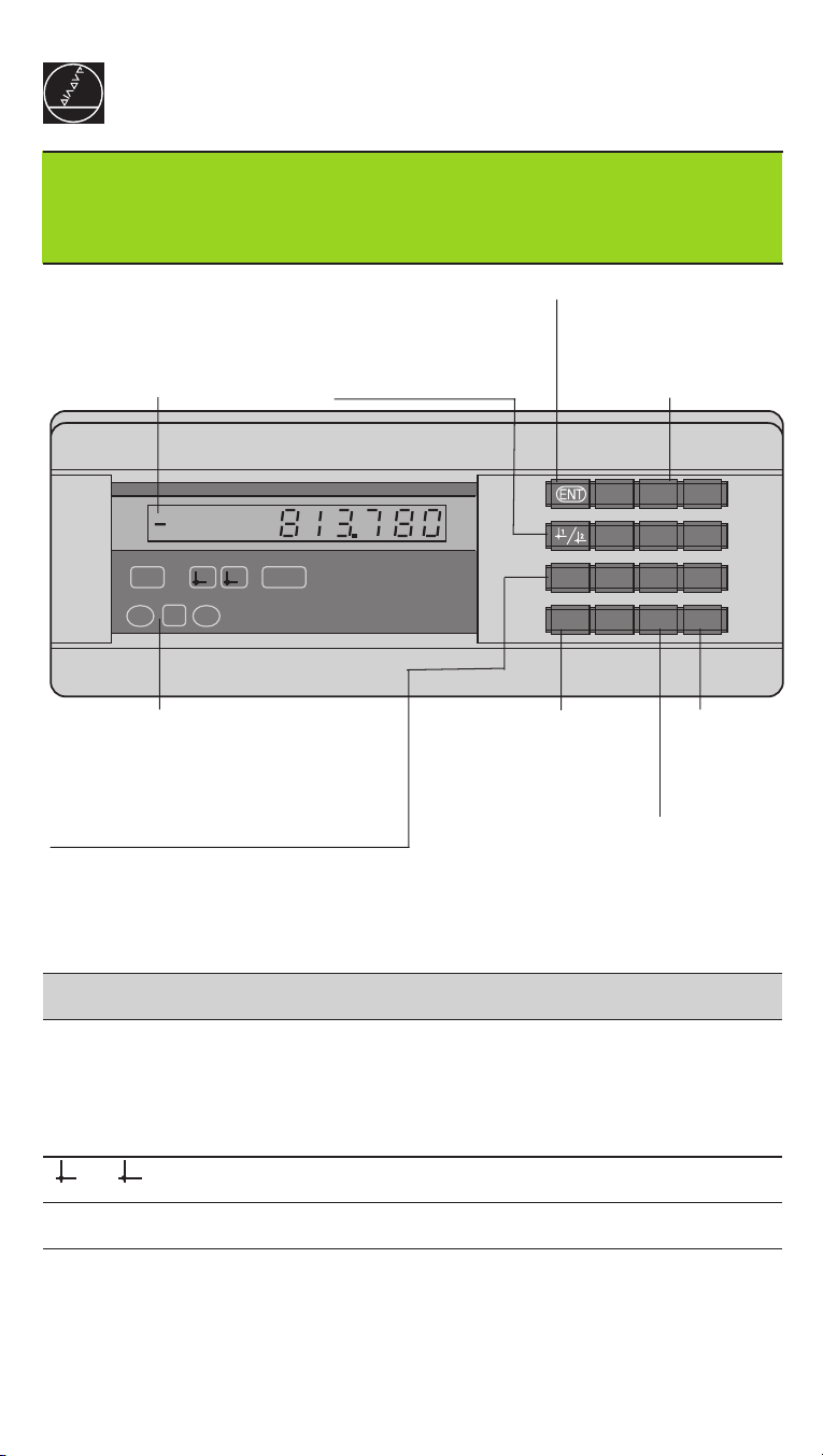
Working with the measured
value display unit
Actual value and input display
(7-segment LED,
9 decades and sign)
• Select datum
• Page backward in
parameter list
ND 261
• Confirm entry value
• Set display to value from
P79 (P80!)
Numeric keypad
789
456
REF21 SET
=
<>
HEIDENHAIN
Status display
• Output measured value over data
interface (P86!)
• Go to parameter list after switch-on
• Page forward in parameter list
Indicator Meaning
REF If decimal points are blinking:
Display is waiting for the reference mark to be crossed over.
If decimal points are not blinking: Reference mark was crossed
over — datum points are now stored in nonvolatile memory.
Blinking: Waiting for operator to press ENT or CL.
1 / 2 Datum 1 / Datum 2 currently active.
• Clear entry
• Reset to zero (P80!)
• CL plus MOD:
parameter list
• CL plus 2-digit number: select parameter
• Clear parameter entry
and show parameter
number
MOD
123
0
CL
.
–
• Algebraic
sign
• Decrease
parameter
value
• Decimal point
• Increase parameter value
SET Blinking: Waiting for operator to confirm entry values.
< / = / > Sorting mode: Measured value less than lower limit /
within tolerance / greater than upper limit.
Page 2
The ND 261 is designed for use with HEIDENHAIN angle encoders with sinusoidal
output signals: either ND 261A for 11 µA
(Id. Nr. 322 352 ..). These angle encoders have one reference mark or several
distance-coded
When a reference mark is crossed over, it generates a signal identifying that position
as a reference point. After switch-on, simply crossing over a reference mark
restores the relationship between axis positions and display values as it was last
defined by datum setting.
With distance-coded reference marks, a maximum traverse of only 10° or 20°
suffices to restore the datum.
reference marks.
(Id. Nr. 283 482 ..) or ND 261V for 1 V
PP
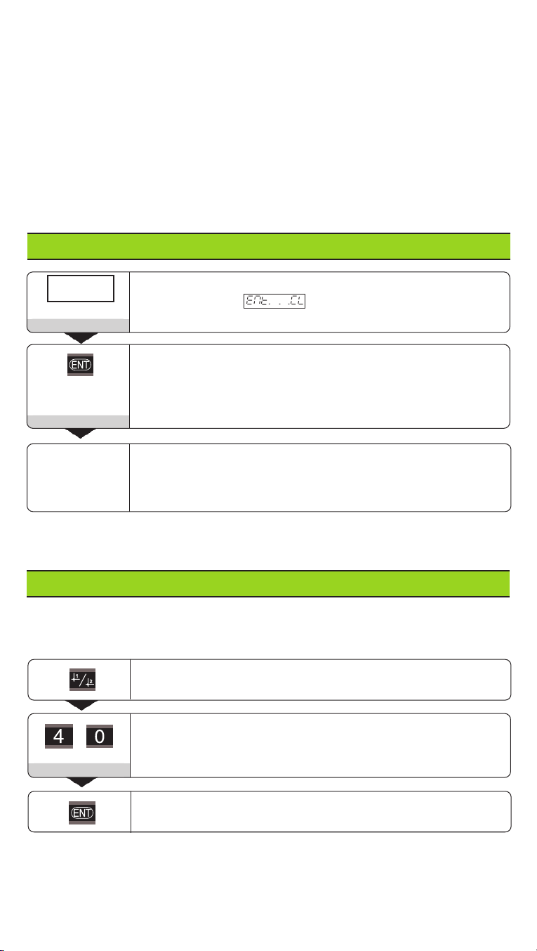
Switch-On
PP
0 ➤1
Ent...CL
5 , 6 9 7
If you do not wish reference mark evaluation, press CL instead of ENT.
Turn on the power (switch located on rear panel).
• Display shows .
• REF blinks.
Switch on reference mark evaluation
• Display shows the value last assigned to the
reference mark position.
• REF indicator glows.
• Decimal point blinks.
Cross over reference mark
Move the axis until the display becomes active and the
decimal point no longer blinks.
Setting the Datum
The datum setting procedure assigns a display value to a specific axis position.
The ND 261 allows you to set two separate datum points.
Select datum 1 or 2.
Enter a value, such as 40.
4 0
Confirm entered value.
You can switch from one datum to the other at any time.
Use datum 2 when you want to display incremental dimensions.
Page 3

Sorting and Tolerance Check Mode
In this mode, the display value is compared with an upper and a lower limit value.
Status indicators and the trigger signal outputs at the D-sub EXT connection (see
that section) indicate whether the display value is less than the lower limit, greater
than the upper limit, or between the two limit values.
Indicator Meaning
= Measured value is between the limit values
< Measured value is less than the lower limit value
> Measured value is greater than the upper limit value
Operating parameters for the sorting mode:
• P17: Sorting on/off
• P18, P19: Limit values
Page 4

Data Output
There are three ways to output data:
➤ PRINT function: Press the MOD key (this method can be inhibited with
operating parameter P86); or
➤ Input the command STX (CTRL B) over the RXD input; or
➤ Input a latch command over the D-sub connection EXT.
A connecting cable (to a PC, for example) is available from HEIDENHAIN
(Id.-Nr. 274 545 ..); cable length up to 20 m (66 ft).
Operating parameters for data output: P50, P51
Wiring and pin layout
Connecting cable is either completely wired (left) or only partially wired (right).
ND
CHASSIS
SIGNAL
TXD
RXD
RTS
CTS
DSR
GND
DTR
2
3
4
5
6
7
20
20
11GND
CHASSIS
2
3
4
5
6
7
SIGNAL
GND
TXD
RXD
RTS
CTS
DSR
GND
DTR
CHASSIS GND: Chassis Ground; TXD: Transmitted Data, RXD: Received Data,
RTS: Request To Send, CTS: Clear To Send; DSR: Data Set Ready; SIGNAL GND:
Signal Ground; DTR: Data Terminal Ready
Signals Signal level "active" Signal level "not active"
ND
CHASSIS
TXD
RXD
RTS
CTS
DSR
GNDSIGNAL
DTR
1GND
2
3
4
5
6
7
20
1 GND
CHASSIS
2
3
4
5
6
7
20
TXD
RXD
RTS
CTS
DSR
GNDSIGNAL
DTR
TXD, RXD –3 V to –15 V +3 V to +15 V
RTS, CTS, DSR, DTR +3 V to +15 V -3 V to -15 V
Data transfer format and control characters
Format ASCII code
Data word 1 start bit, 7 data bits, parity bit (even parity), 2 stop bits
Control characters Call measured value: STX (CTRL B), interrupt DC3 (CTRL S),
resume DC1 (CTRL Q)
Enquire error message: ENQ (CTRL E)
Sequence • Sign • Numerical value with up to 2 decimal points
• Blank space (or ? for error)
• Comparison result (<, >, =; ? if P18 > P19) or blank space
• 1 blank space • Carriage return • Line feed
Storage and transfer times
The duration of data transfer depends on the selected baud rate and the number of
additional line feeds. Display of degrees, minutes and seconds increases the storage
and transfer times.
Latch signal STX (CTRL B) EXT (pulse) EXT (contact) PRINT
Storage time ≤ 1 ms ≤ 1 µs ≤ 5 ms ≤ 42 ms
Transfer time ≤ 44 ms ≤ 44 ms ≤ 48 ms ≤ 85 ms
Page 5

D-Sub Connection EXT
Danger to internal components!
Voltage sources from external circuitry must conform to the recommendations in EN 50178 for low-voltage electrical separation. Connect inductive
loads only with a quenching diode parallel to the inductance.
Use only shielded cable!
Connect the shield to the connector housing.
Pin Function Pin Function
15 Meas. value ≥ trigger limit A1 (P62) 1 0 V
16 Meas. value ≥ trigger limit A2 (P63) 10 0 V
17 Meas. value < lower sorting limit (P18) 5 Do not use
18 Meas. value > upper sorting limit (P19) 6 Do not use
OutputsInputs
19 Error (see “Error Messages” ) 7 Do not use
14 Display value is zero 8 Do not use
2 Reset display to zero, clear error message 9 Do not use
3 Preset display to value from P79 12 Do not use
25 Cross over reference marks 13 Do not use
4 Ignore reference mark signal 24 Do not use
22 Pulse: output the measured value 11 Vacant
23 Contact: output the measured value 20 Vacant
21 Vacant
Signal levels LOW HIGH
Inputs –0.5 V ≤ U ≤ 0.9 V I ≤ 6 mA 3.9 V ≤ U ≤ 15 V
Outputs U ≤ 0.4 V I ≤ 100 mA U ≤ 32 V I ≤ 10 µA
Description of input and output signals
Input signals • Internal pull-up resistor 1 kΩ
• Triggering by make contact against 0 V or
• LOW level over TTL component
• Delay for Zero reset/Preset: t
• Minimum pulse duration for all signals: t
Output signals • Open collector outputs,
• active LOW
• Signal output delay:
≤ 42 ms
• t
d
• Zero crossover signal
minimum duration,
trigger outputs A1, A2:
t0 ≥ 180 ms
d
B
≤ 2 ms
C
U
CE
E
Pin 1.10
≥ 42 ms
min
I ≤ 100 mA
+ UB ≤ 32 V
0 V
Note that these times will increase if features are active (such as the sorting
mode) or if the measured values are being displayed in degrees/minutes/seconds.
Page 6

Display Freeze by Measured Value Output Signal
The effect of the signal for measured value output on the display is defined in user
parameter P23.
➤ Concurrent display: No display freeze. The unit shows the current measured
value ( ).
➤ Frozen display: The display is frozen and is updated with each signal for meas-
ured value output ( ).
➤ Frozen/concurrent display: The display freezes only as long as the signal is
present ( ).
Error Messages
To clear error message
When you have removed the cause of the error,
➤ press CL.
Message Cause and effect
Last measured value not yet latched
External device not ready for data transfer
( only appears once)
Data interface:
Parity error or wrong format
1)
Incorrect input value
Overflow caused by external preset
Overflow, trigger limit 1
Overflow, trigger limit 2
Overflow, lower sorting limit
Overflow, upper sorting limit
Encoder signal too weak1) (encoder may be contaminated)
Input frequency too high for encoder input
(will occur for example when traverse speed too high)
Internal counter overflow
Error while crossing over reference marks
To clear the error message: Switch off the display unit.
Should any of these error codes recur, contact your HEIDENHAIN
service agency
1)
1)
1)
1)
Offset compensation values for encoder signals have been
erased: contact your HEIDENHAIN service agency.
Erase the operating parameters.
If all decimal points light up, the measured value is too large or too small.
In this case, set a new datum or retract.
If all sorting indicators light up, this means that the upper sorting limit is less
than the lower limit.
1)
These errors are significant for a connected device. The error signal (pin 19) at the
EXT D-sub connection is active.
Page 7

Operating Parameters
The parameters are divided into “user parameters“ and “protected operating
parameters," which can only be accessed by entering a code number.
User parameters
User parameters are operating parameters that you can change without entering
the code number: They are designated P00 to P30, P50, P51, P79, P86
Calling user parameters
To call user parameters immediately after switch-on:
➤➤
➤ Press the MOD key as long as is visible in the display.
➤➤
To call user parameters during operation:
➤➤
➤ Press and hold the CL key, then press MOD.
➤➤
To go directly to a specific user parameter:
➤➤
➤ Press and hold the CL key, then press the first digit of the parameter number.
➤➤
➤➤
➤ Release both keys and press the second digit.
➤➤
Protected operating parameters
Before you can change protected operating parameters you must enter the code
number 95 148 through : They remain accessible until you switch
off the position display.
To page through the parameter list
➤➤
➤ Forward paging: Press the MOD key.
➤➤
➤➤
➤ Backward paging: Press the 1 / 2 key.
➤➤
By paging on, you automatically enter any change you've made in a parameter.
To change operating parameters
➤➤
➤ Increase the parameter value with the decimal point key, or
➤➤
➤➤
➤ Decrease the parameter value with the minus key, or
➤➤
➤➤
➤ Enter the numerical value for the operating parameter, e.g. for P79 ( SET blinks).
➤➤
To correct your entries and show the parameter designation
➤➤
➤ Press the CL key.
➤➤
To exit the operating parameters
➤➤
➤ Press ENT. All changes made become effective.
➤➤
Operating Parameter List
Parameter Meaning Function / Effect Setting
Enter code number 95 148 to change a protected operating
parameter.
Display mode Decimal degrees
Display
Classification
Angle display
Sorting mode Sorting on
Lower sorting limit (ensure that P18 < P19)
Upper sorting limit
Degrees, minutes, seconds
+
/– 180°
360°
+
∞
/–
Sorting off
(ensure that P19 > P18)
Page 8

Parameter Meaning Function / Effect Setting
Display value Concurrent display, no freeze
Display
Direction
Subdivision
Decimal point
Encoder
Preset
MesMes
Messa
MesMes
Mod
e PRINT not inhibited
with measured Frozen display / update with signal
value output Frozen/concurrent display
Counting Normal (
direction Inverse (
Angle subdivision
400, 250, 200, 100, 80, 50, 40, 25, 20, 10, 8, 4, 2.5, 2, 1, 0.4, 0.2
Counting 0-1-2-3-4-5-6-7-8-9-0
mode 0-2-4-6-8-0
0-5-0
Places after decimal 1 / 2 / 3 / 4 / 5 / 6
Reference One reference mark
marks Distance-coded with 500 • SP
(SP = signal period)
Distance-coded with 1000 • SP
(e.g. for ROD 250 C / ROD 700 C)
Distance-coded with 2000 • SP
Distance-coded with 5000 • SP
Reference mark Evaluation
evaluation No evaluation
Encoder No monitoring (
monitoring Contamination
Frequency
Contamination and frequency
Baud rate
Additional line feeds
Trigger limit 1 Enter numerical value
Trigger limit 2 Enter numerical value
Value for Enter numerical value
datum switching input or with ENT key
Reset/Preset No zero resert/Preset with CL/ENT
Display after message displayed
gg
ge
switch-on message not displayed
gg
External REF REF over D-sub connection EXT
Inhibit PRINT PRINT inhibited
110, 150, 300, 600, 1200, 2400, 4800, 9600
Zero reset with CL (
no preset with ENT
Zero reset with CL and
preset with ENT to value in P79
No REF over EXT connection
Positive
Negative
(
)
)
Alarm Off
Linefeed
)
) 0 to 99
for datum setting over
Set Zero
),
Page 9

Parameter Settings for HEIDENHAIN Angle Encoders
Model
Subdivision
P36
11 µA
/ 1 V
PP
PP
Signal
periods per
revolution
P43
Reference
marks
Display
step
/ RPD 486 3 600 one single 0.01° 10 1
/ ROD 1080 0.005° 20 5 3
0.001° 100 1 3
ROD 250C/ROD 280C 9 000 one single 0.005° 85 3
RON 255C/RON 285C 0.001° 40 1 3
ROD 250C/ROD 280C 18 000 dist.c 1000 0.001° 20 1 3
/ROD 282C 0.000 5° 40 5 4
RON 255C/RON 285C 0.000 1° 200 1 4
/RON 287C
ROD 700C/ROD 780C
RON 705C/RON 785C
RON 706C/RON 786C
RON 905 / 36 000 one single 0.000 1° 100 1 4
ROD 800C/ROD 880C 36 000 dist.c 1000 0.000 1° 100 1 4
RON 806C/ROD 886C
Count.
mode
P37
Decim.
places
P38
Example: Set parameters for any encoder
s
Angle encoder with line count
Desired display step
Subdivision P36
a
= 0.001°
= =
= 360° / s / a = 20
= =
= 18 000
Counting mode P37 = 1 (display counts 1, 2, 3, ....)
Decimal places of a: P38 = 3
Convert decimal degrees to degrees, minutes, seconds
1 degree (1°) = 60 minutes (60'); 1 minute (1') = 60 seconds (60'')
1 second (1'') ≈ 0.000278°
Page 10

Rear View
RS-232-C/V.24
data interface
100 ... 240 V
50 ... 60 Hz
X31 (V.24 /RS-232-C)
X41 (EXT)
X1
D-sub connection
EXT
Power switch
Ground terminal
ND 261A, Id. Nr. 283 482 ..
Angle encoder input: 11 µA
Connecting cable: max. 30 m
PP
Max. input frequency: 100 kHz
ND 261V, Id. Nr. 322 352 ..
Angle encoder input: 1 V
Connecting cable: max. 60 m
PP
Max. input frequency: 300 kHz
Interfaces X1, X31 and X41 interfaces comply with the recommendations
in EN 50178 for separation from line power.
Installation
172 ± 0.2
You can fix the display unit to a flat surface with M4
6.77 ± .008"
bolts (see illustration at right).
The units can also be stacked. Adhesive inserts (in-
cluded in delivery) prevent them from sliding.
Power Supply and Connection
Danger of electrical shock!
Unplug the power cord before opening the housing.
Connect a protective ground. This connection must never be interrupted.
Danger to internal components!
Do not engage or disengage any connections while the unit is under power.
Use only original replacement fuses.
Primary-clocked power supply.
Voltage range: 100V to 240V (– 15% to + 10%) Frequency: 48 Hz to 62 Hz
Power consumption typ. 8 W Line fuse: F 1 A (in unit)
Minimum cross-section of the power line: 0.75 mm
2
140 ± 0.2
5.51 ± .008"
To increase noise immunity, connect the ground terminal on the rear panel to
the central ground point of the machine. (Minimum cross section of the connecting cable: 6 mm²).
Ambient Conditions
Temperature range Operation: 0 °C to + 45 °C (32 °F to 113 °F)
Storage: – 30 °C to + 70 °C (– 22 °F to 158 °F)
Rel. humidity Annual average: < 75%; maximum: < 90%
Weight 1.5 kg
DR. JOHANNES HEIDENHAIN GmbH
Dr.-Johannes-Heidenhain-Straße 5
D-83301 Traunreut, Germany
(0 86
69) 31-0 . 56 832
FAX
(0 86
69) 50 61
Service (0 86 69) 31-12 72
TNC-Service (0
FAX
86
69) 98 99
(0
http://www.heidenhain.de
284 250-26 · SW 246 183 01 · 1 · 2/2000 · H · Printed in Germany · Subject to change without notice
Tx
86
69) 31-14 46
 Loading...