

Page 1
Operating Instructions
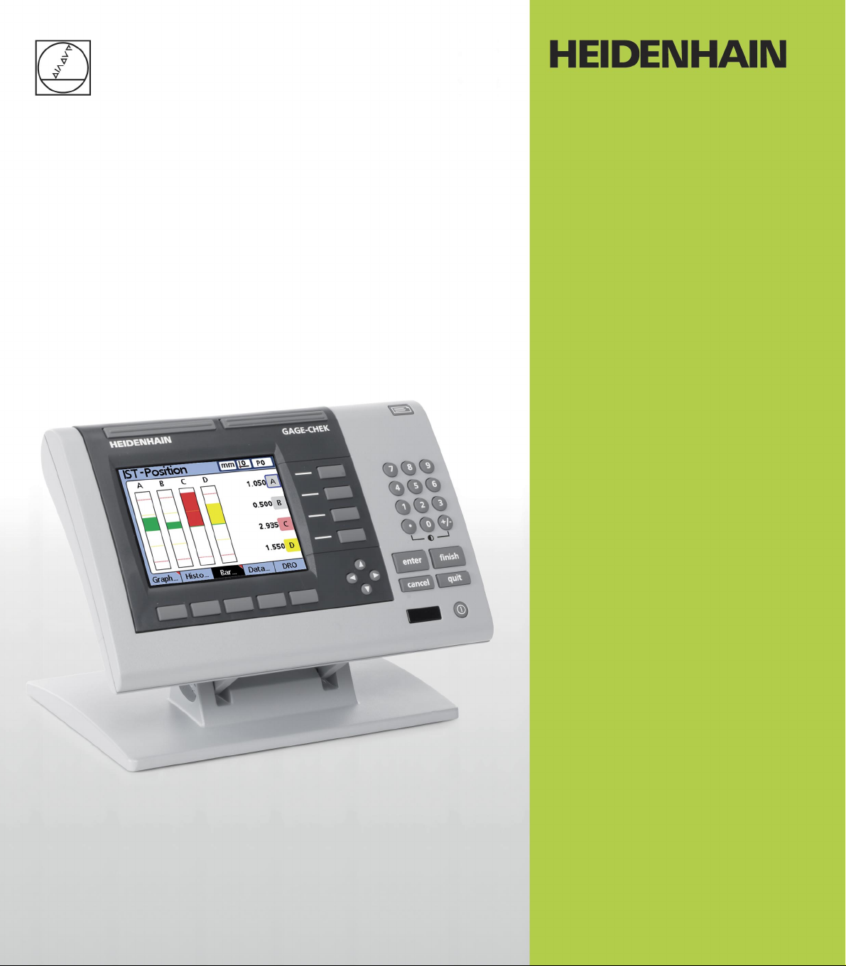
ND 2100G
GAGE-CHEK
Software Version
2.60.x
English (en)
10/2011
Page 2

Page 3
ND 2100G Introduction
quit
cancel
enter
finish
+/-0
4
1
7
5 6
2 3
8 9
11
2345789
6
quit
cancel
enter
finish
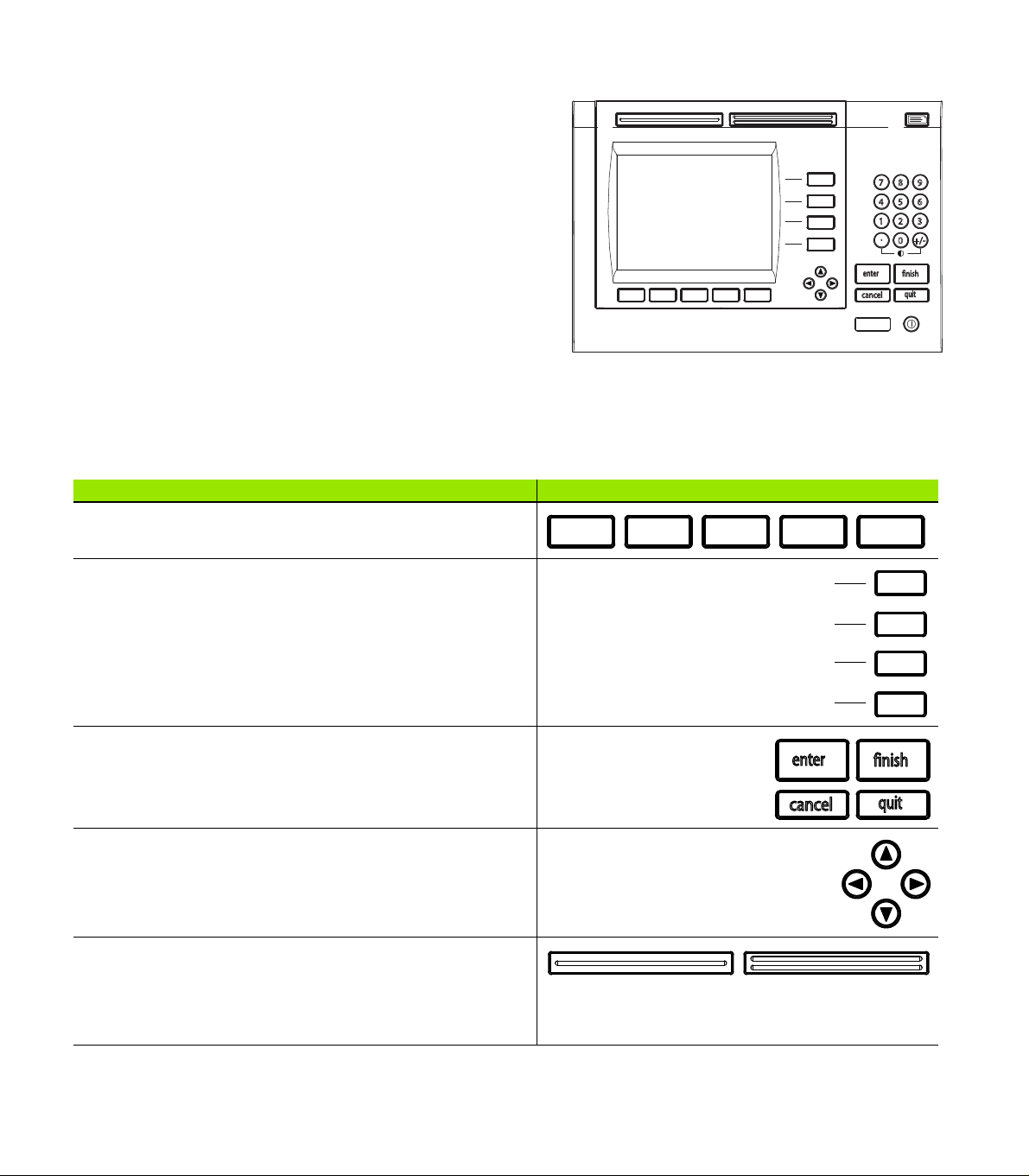
1 LCD screen
2 Soft keys
3 Dimension keys
4 Command keys
5 Arrow cursor keys
6 Numeric Keypad
7 Fast track keys
8 Send key
9 LCD on/off key
ND 2100G panel keys
Panel keys are used to initiate feature measurements, apply
tolerances, send reports of measurement results and configure
operational parameters.
Panel function key Panel key
Soft keys: Functions change in support of the activities displayed
on the LCD.
Dimension keys: Can be assigned one of six hot key functions
for use when DRO screen is displayed. When graph, bar value or
data screens are displayed, dimension keys are used to display
values for single dimensions or a smaller group of dimensions.
Command keys: Control measurement and data entry
processes.
Arrow cursor keys: Used to scroll through lists and navigate
menus and setup screen data fields.
Fast track keys: Two programmable fast track keys are used to
perform frequently used functions. These keys can easily be
located by touch without taking your eyes off the part. Users can
program either fast track key as described later in the Hotkeys
portion of Chapter 2: Installation, Setup and Specifications.
ND 2100G GAGE-CHEK 3
Page 4
Panel function key Panel key
+/-0
4
1
7
5 6
2 3
8 9
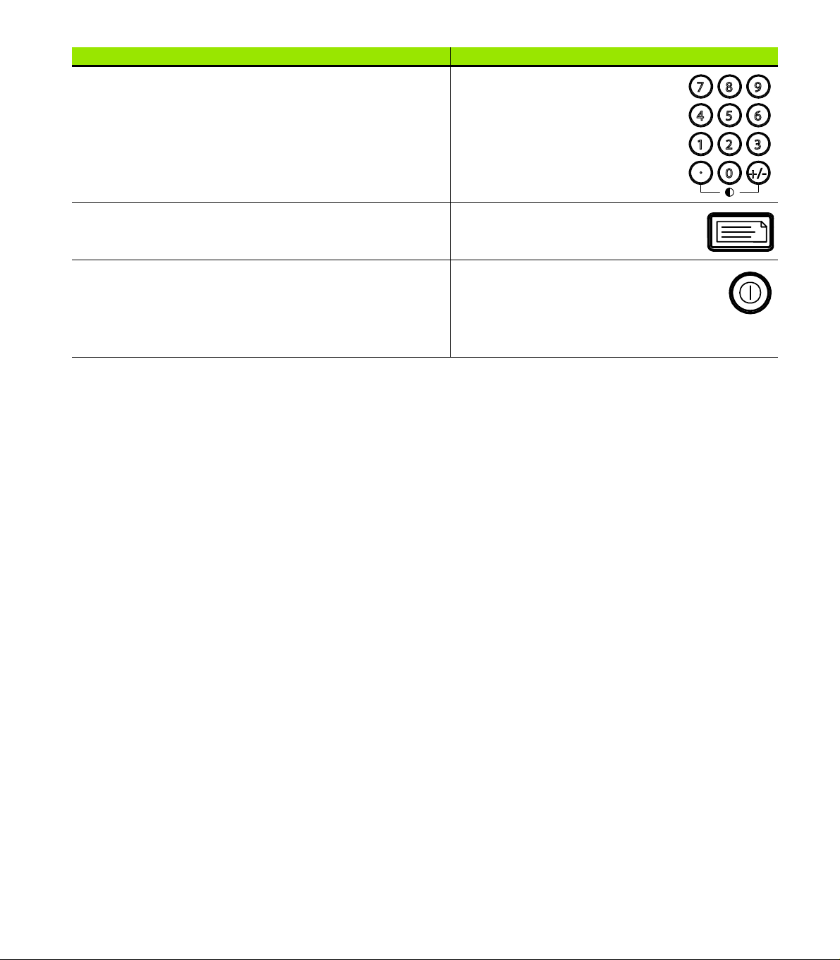
Numeric keypad: Used to enter numeric data. Additionally, the
decimal point key and +/- key are used to adjust the contrast
of the LCD display.
Send key: Used to transmit measurement results to a computer,
USB printer or USB flash drive.
LCD On/Off key: Press the LCD on/off button to turn the LCD
display off without removing power from the ND 2100G. Press
the button a second time to restore the LCD display. Additionally,
the LCD On/Off key can be used to clear channel calibrations,
delete data stored for a single part or delete data stored for all
parts.
4 Preface
Page 5
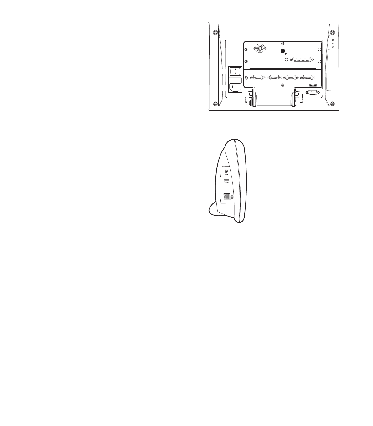
ND 2100G rear panel
1321516147
11
12
3
1 Power switch
2 Power connection with fuse
3 Ground (protective ground)
4 Encoder inputs
5 Relay outputs
6 Parallel I/O port
7 RS-232-C interface
ND 2100G side panel
1 Speaker/headset jack
2 USB Type A connector
3 RJ-45 Foot switch/hand switch/keypad connector
ND 2100G GAGE-CHEK 5
Page 6
Information contained in this
manual
This User's manual covers the operation, installation, setup and
specifications of the ND 2100G. Operating information is contained in
chapter 1. Installation, setup instructions and specifications are
contained in chapter 2.
Fonts used in this manual
The following fonts are used to indicate operator controls or to show
emphasis:
Operator controls - soft keys and other panel keys are shown in
upper case
Emphasis - Items of special interest or concepts that are
emphasized to the user are shown in bold type
Showing sequences of key presses
The ND 2100G user performs sequences of soft key and panel key
presses to measure part features and complete other tasks. These
sequences are indicated using text as shown in the following
example:
Press the MENU... soft key, press the DATUM... soft key and then
press the MASTER soft key is sometimes abbreviated as:
Press MENU/DATUM/MASTER
Symbols within notes
Notes are marked with symbols on the left indicating the type, or
potential severity of the information.
General Information
This is additional or supplementary information about an
activity or concept.
Warning
This warns of a situation or condition that could lead to
measurement errors, equipment malfunction or
equipment damage. Do not proceed until the message is
read and understood.
Caution - Risk of electric shock
This warns of a situation or condition that could lead to
electrical shock and to personal injury or death. Do not
proceed until the message is read and understood.
6 Preface
Page 7

Safety considerations
General accepted safety precautions must be followed when
operating the system. Failure to observe these precautions could
result in damage to the equipment, or injury to personnel. It is
understood that safety rules within individual companies vary. If a
conflict exists between the material contained in this manual and the
rules of a company using this system, the more stringent rules should
take precedence.
The ND 2100G is equipped with a 3-wire power plug that
includes a separate ground connection. Always connect
the power plug to a 3-wire grounded outlet. Use of 2-wire
power plug adapters or any other connection accessories
that remove the third grounded connection create a safety
hazard and should not be permitted.
Unplug the ND 2100G from the power outlet and seek the
assistance of a qualified service technician if:
The power cord is frayed or damaged or the power plug
is damaged
Liquid is spilled or splashed onto the enclosure
The ND 2100G has been dropped or the exterior has
been damaged
The ND 2100G exhibits degraded performance or
indicates a need for service some other way
ND 2100G channel inputs
The ND 2100G can be connected to the following channel
configurations.
1, 4, or 8 single input channels
Up to 16 networked RS-232 input channels
Or combinations of single input channels and networked RS-232
input channels for a total of up to 16 channels
Software version
The software version is shown in the About setup screen discussed
later in chapter 2.
Cleaning
Use only a cloth dampened with water and a mild detergent for
cleaning the exterior surfaces. Never use abrasive cleaners, and never
use strong detergents or solvents. Only dampen the cloth, do not use
a cleaning cloth that is dripping wet.
ND 2100G GAGE-CHEK 7
Page 8

8 Preface
Page 9

1 Operation .... 17
1.1 ND 2100G Overview .... 18
Overview .... 18
1.2 Basic operation of the ND 2100G .... 20
Switching on the ND 2100G .... 20
Switching off the ND 2100G .... 20
1.3 Panel key descriptions .... 21
Dimension keys .... 23
1.4 LCD screens and menus .... 26
Screen navigation .... 26
Home screen .... 27
DRO screen .... 27
View soft keys and screens .... 28
View soft keys for subgroups of one .... 28
Dimension graphs for SPC subgroups of one .... 28
Dimension histograms for SPC subgroups of one .... 29
Bar and dial current value displays .... 30
Dimension data tables for SPC subgroups of one .... 31
View soft keys for subgroups greater than one .... 32
Dimension x
Dimension r charts for subgroups greater than one .... 33
Dimension data tables for subgroups greater than one .... 34
in/mm menu items .... 35
Master menu items and screens .... 35
Master screen for calibrating encoder datums .... 35
Master screen for calibrating transducer ranges .... 36
Menu soft keys .... 37
The datum menu functions .... 37
The Extra menu functions .... 38
Fast3 .... 39
Setup menu functions .... 40
charts for subgroups greater than one .... 32
ND 2100G GAGE-CHEK 9
Page 10

1.5 Operating instructions .... 41
Select a part to begin a measurement .... 42
Establish a reference for the measurement .... 43
Calibrating channels using the Master function .... 43
Calibration of a single reference point .... 44
Calibration groups (G1, G2, G3...G18) .... 45
Calibrations of transducer resolution (Min-Max calibrations) .... 46
Establishing a temporary dimension reference .... 48
Zeroing a dimension reference .... 48
Presetting a dimension reference to a specific value .... 49
Clearing channel calibrations .... 50
Clearing dimension references (presets) .... 50
Conducting measurements .... 51
Manual measurements .... 51
Sequential measurements .... 52
Dynamically sampled measurements .... 53
Semi-automated measurements .... 54
Reviewing measurements .... 55
Printing reports or sending results to a computer .... 55
Printing reports .... 55
Sending data to a computer .... 56
Data reports .... 57
Clearing stored measurement data .... 58
10
Page 11

2 Installation, Setup, Formulas and Specifications .... 59
2.1 ND 2100G Shipment Contents .... 60
Items included with the ND 2100G .... 60
Optional items possibly included .... 60
Repackaging the ND 2100G .... 61
2.2 Hardware Installation .... 62
Assembling the mounting stand .... 62
Benchtop location and mounting .... 62
Arm mounting (optional) .... 63
Connecting power .... 64
Connecting channel inputs .... 65
Connecting a computer .... 66
Connecting headphones and USB printer .... 66
Connecting headphones .... 66
Connecting a USB printer .... 66
Connecting an optional foot switch or remote keypad .... 67
2.3 Software setup .... 68
Setup menu .... 69
Accessing and navigating the Setup menu .... 70
Using dimension keys in the setup mode .... 71
Entering data into setup fields .... 71
Deleting data entries .... 72
Entering setup parameters .... 72
Changing the channel or dimension number .... 72
Entering parameters .... 73
Copying parameters to other parts, dimensions or channels .... 73
Saving a parameter and advancing to the next .... 74
Saving a parameter and returning to the Setup menu .... 74
Discarding changes and returning to the Setup menu .... 74
Leaving the Setup menu .... 75
Printing ND 2100G setup configurations .... 75
Saving or loading ND 2100G configurations .... 75
Minimum setup requirements .... 76
Setup screens .... 76
About setup screen .... 76
Dimensions setup screen .... 77
Creating part numbers .... 77
Selecting part numbers .... 77
Labeling parts and dimensions .... 78
Defining visible and hidden dimensions .... 78
Copying dimension parameters to other parts .... 79
Deleting parts .... 79
Formats setup screen .... 80
Specifying a dimension .... 80
Specifying radius or diameter .... 80
Display resolution .... 81
Formulas setup screen .... 82
Variables setup screen .... 83
ND 2100G GAGE-CHEK 11
Page 12

Tolerances setup screen .... 84
Nominal values with tolerances .... 85
Nominal with +/- tolerances .... 85
Nominal with ++ tolerances .... 86
Nominal with -- tolerances .... 87
Nominal with fixed limits .... 88
Specifying an audio alert .... 89
Mirror values .... 90
SPC setup screen .... 91
Subgroup size .... 91
Max subgroups .... 91
Graph points .... 92
Next record ID .... 92
Dimension .... 92
UCL and LCL .... 93
x
, r Ucl and Lcl .... 93
Warning limits .... 95
Showing and hiding SPC graphs .... 95
Header setup screen .... 96
Labels .... 96
Prompts .... 96
Memory setup screen .... 97
S labels setup screen .... 97
S formulas setup screen .... 98
Globals setup screen .... 98
Channels setup screen .... 99
Specifying the input channel .... 99
Selecting the channel input type .... 100
Specifying input channel setup parameters .... 101
Master link probe balancing .... 101
Setting the resolution for the linked channels .... 102
Specifying channel input resolution .... 103
Specifying units of measure .... 104
Reversing channel input polarity .... 104
Specifying encoder reference marks .... 105
Changing the machine zero position .... 106
Enabling scale error notification .... 106
Calibrating LVDT and HBT transducer gain .... 106
Centering (nulling) LVDT and HBT transducers .... 107
Selecting an external RS-232 channel .... 108
Specifying an RS-232 input port .... 108
EnDat 2.2 encoder interface .... 109
Master setup screen .... 111
Specifying the number of calibration points .... 111
Selecting calibration type .... 111
Locking the calibration process if warnings occur .... 112
Specifying a calibration interval .... 112
Using dynamic Min/Max values for calibration .... 113
Specifying Min and Max calibration warnings .... 114
12
Page 13

SLEC setup screen .... 115
SLEC or LEC, which is right for my application? .... 115
LEC (Linear error correction) .... 115
SLEC (Segmented linear error correction) .... 116
SLEC setup procedure .... 118
Clear all datums .... 118
Cycle power & set machine zero .... 119
Clear old values & disable SLEC .... 120
Enter machine zero offset .... 121
Enter new station values .... 122
Enable SLEC .... 123
Display setup screen .... 123
Radix for numeric displays .... 123
Display mode for angles .... 123
Startup angular and linear display modes .... 124
Bar graph orientation .... 125
Bar graph or dial displays .... 125
Colors that indicate measurement results .... 125
Units of measure .... 126
Home screen .... 126
Report setup screen .... 127
Record number .... 128
Lines per page .... 128
Columns per page .... 129
Type of records to be printed .... 129
Report characters setup screen .... 130
Send setup screen .... 132
Auto Send Rec .... 132
Record Number .... 132
Record date, label and units of measure .... 132
Record content .... 133
Min Dimen Size .... 133
Send characters setup screen .... 134
Parallel setup screen .... 135
Remote control .... 135
I/O Debounce interval .... 135
RS-232 setup screen .... 136
Uart Id .... 136
Baud rate .... 136
Word length .... 136
Stop bits .... 137
Parity .... 137
Handshaking .... 137
End of character (EOC) delay .... 137
Specifying end of line (EOL) delay .... 138
Serial port data type .... 138
ND 2100G GAGE-CHEK 13
Page 14

USB setup screen .... 139
Data .... 139
Destination .... 139
File type .... 140
Current auto (file) number .... 140
Hot Keys setup screen .... 141
Front panel keys for hot key mapping .... 141
Remote switches and parallel port pins for hot key mapping .... 142
Assigning hot key functions .... 143
Clock setup screen .... 152
Setting the date and time .... 152
Date format .... 152
Time format .... 153
External edge setup screen (optional) .... 154
Edge input .... 154
External edge probe timing .... 154
Edge Type .... 155
Direction factor .... 155
Teaching a probe diameter .... 157
Misc. setup screen .... 158
Key delay .... 158
Speaker volume .... 158
Data entry message time .... 158
Switch view .... 159
Cpk/Ppk display .... 159
Slew limit .... 159
Start Scr saver .... 159
Scr Saver Off .... 160
Startup hold .... 160
Strict Unit Check .... 160
Supervisor setup screen .... 161
Password .... 161
Unlocking and locking critical functions .... 161
14
Page 15

2.4 Formulas .... 163
Introduction to formulas .... 163
How do formulas relate inputs to dimensions? .... 165
Visible or hidden dimensions? .... 165
Visible dimensions .... 165
Hidden dimensions .... 165
When are dimensions stored in the ND 2100G database? .... 166
What can formulas do? .... 166
When are formulas constructed or edited? .... 167
How can formulas be recorded for safekeeping? .... 167
Constructing and editing formulas .... 168
Formula setup screen .... 168
Formula construction example .... 171
Long formulas .... 175
Deleting formula elements .... 175
Formula functions .... 176
Basic and advanced formula functions .... 177
Basic formula functions .... 178
Channel functions .... 179
Dimension functions .... 181
Arithmetic operators .... 183
Units of measure .... 184
Basic math functions .... 185
Exponent function (exp) .... 186
Trig and inverse trig functions (sin through atan) .... 187
Absolute value (abs) function .... 188
Integer function (int) .... 189
Pi and other constants .... 190
Advanced formula functions .... 191
Commas (,) .... 194
Semicolon (;) .... 195
Logical and control .... 196
Din .... 198
Dout .... 198
MinIndex and MaxIndex .... 199
RsetDyn .... 199
If function .... 200
Case function .... 201
Minimum (min) and maximum (max) functions .... 204
Average (avg) and median (md) functions .... 206
Modulo (mod) function .... 207
Sequence (seq) function .... 208
Trip function and measurement automation .... 212
Dynamic minimum (Dmn) and dynamic maximum (Dmx) functions .... 215
Dynamic average (Davg) and dynamic median (Dmd) functions .... 217
Fail function .... 218
ND 2100G GAGE-CHEK 15
Page 16

Xtra menu functions .... 219
Ask function .... 222
Beep function .... 223
Clear all data function .... 224
Clear data function .... 224
ClrTrig, SetTrig and user defined events .... 225
OnEvent function .... 226
DateStr function .... 228
TimeStr function .... 228
Time function .... 229
Din and DinBin function .... 230
Din .... 230
DinBin .... 232
Dout and DoutBin function .... 233
Dout .... 233
DoutBin .... 235
Display function .... 237
FnDefine, FnParam and FnCall functions .... 238
Variable and Global functions .... 240
Variables .... 240
Globals .... 242
Loop function .... 243
Remark function .... 244
HwDmn and HwDmx functions .... 245
RsetDyn function .... 245
HwLx function .... 246
Lookup and data lookup .... 247
Master function .... 250
MaxIndex and MinIndex functions .... 251
PartNo function .... 252
Preset function .... 253
Recall function .... 254
Relay function .... 255
Report function .... 257
Scan function .... 258
Send function .... 263
SendMsg function .... 264
SendRec function .... 265
SetColor function .... 266
Setup function .... 267
Xlatch function .... 268
2.5 Specifications .... 270
Dimensions .... 272
Arm mount bracket .... 273
16
Page 17

Operation
Page 18
1.1 ND 2100G Overview
Overview
The ND 2100G is an advanced digital readout system for performing
single or multiple gage measurements at very high levels of precision
and accuracy. Dimensional inspections of components are performed
using encoders or transducers as part of in-line production activities,
or final quality inspection. Measurements are conducted under
operator control, or are semi-automated and conducted in conjunction
with a fixtured gage system.
The ND 2100G is configured at the factory to support
One, four or eight single-input channels, or
Up to 16 multiplexed RS-232 input channels, or
1.1 ND 2100G Overview
Combinations of single-input channels and multiplexed RS-232 input
channels for a total of up to 16 channels
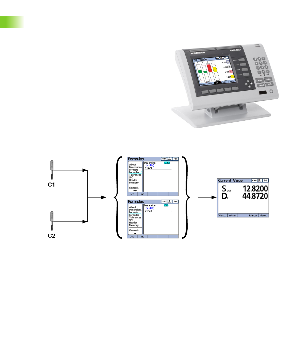
Channel inputs can be algebraically combined or processed by
powerful math and control formulas to display dimensions such as
flatness, volume and runout. Formulas are created as part of the
ND 2100G setup using straightforward screen control and math
functions.
C1=28.846 mm Sum=C1+C2 Sum=12.820
C2=-16.026 mm Dif=C1-C2 Dif=44.872
Channel inputs are processed by formulas to display dimensions.
18 1 Operation
Page 19

The intuitive user interface includes a large character color LCD for fast
and accurate measurement feedback. User interface screens include
a digital readout of current values, bar and dial position value
indicators, graphs of values, histograms of measurement statistics
and tables of measurement and of SPC data.
Digital readout (DRO) Horizontal bar Vertical bar Dial
Graph of values Histogram of values Measurement data SPC data
1.1 ND 2100G Overview
ND 2100G GAGE-CHEK 19
Page 20

1.2 Basic operation of
finish
the ND 2100G
Switching on the ND 2100G
Switch on the ND 2100G. The POWER switch is
located on the rear of the enclosure. After switching
the power on, or after a power failure, the power-up
screen will be displayed.
Press the FINISH key to advance from the power-up
screen to the home screen.
Your ND 2100G is now ready for operation.
1.2 Basic operation of the ND 2100G
Switching off the ND 2100G
Power-up screen.
Switch the ND 2100G off. The parts, formulas and
dimensions that have been saved during operation
will be retained in memory.
20 1 Operation
Page 21
1.3 Panel key descriptions
quit
cancel
enter
finish
+/-0
4
1
7
5 6
2 3
8 9
enter
finish
cancel
quit
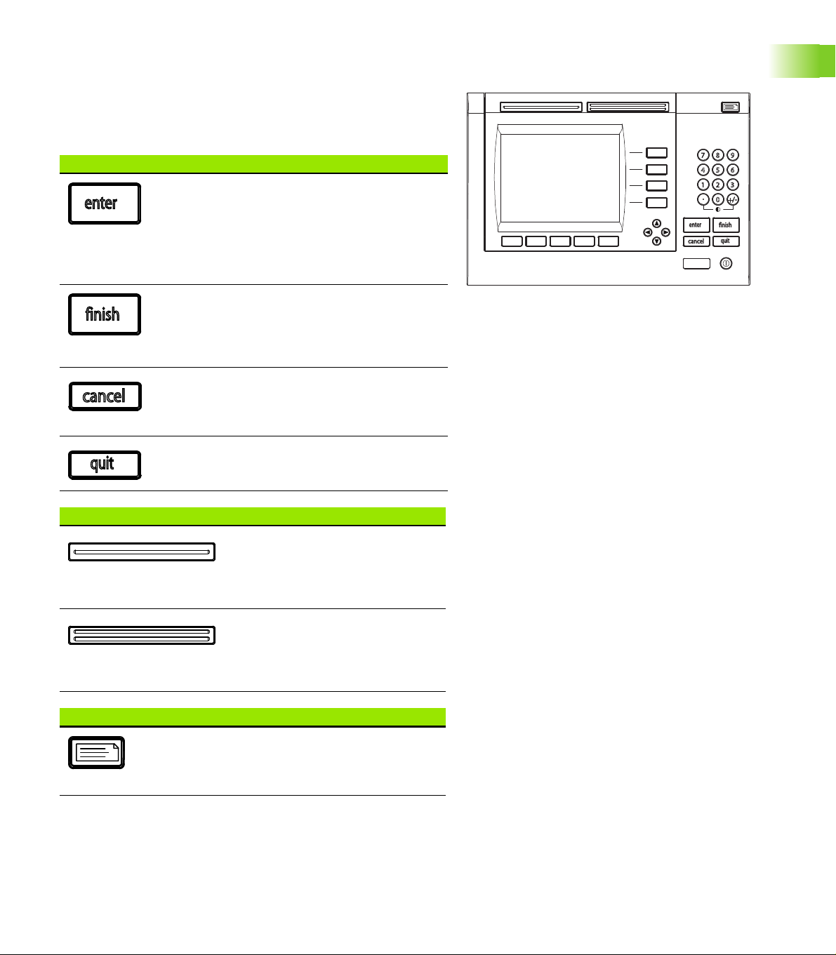
Descriptions of panel key functions are provided in the following
pages for Command, Fast Track, Send, LCD On/Off and Arrow Cursor
keys. Soft key functions are also described later as part of LCD
screens and menus.
Command keys Function
Enter data: Press the ENTER key to enter
data for a measurement. Information on the
LCD is stored as measurement or
configuration data. This information includes
current dimension values or alphanumeric
data for a configuration or user prompt data
field.
Exit a screen: Press the FINISH key to exit a
screen saving any changes that were made.
The FINISH key may also be used to return
from the display of measurement or SPC data
to the current home screen.
Delete data or features: Press the CANCEL
key to erase the last data value entered into
the system from the numeric keypad or
delete data in configuration fields.
Quit current activity: Press the QUIT key to
abort the current task and return to the home
screen or to exit the current menu.
Fast Track keys Function
Left frequently used function:
Press the LEFT WIDE key to initiate
the function programmed for this
key. The factory default function for
this key is RSETDYN.
Right frequently used function:
Press the RIGHT WIDE key to
initiate the function programmed for
this key. The factory default function
for this key is ENTER.
ND 2100G Panel keys.
1.3 Panel key descriptions
Send key Function
Transmit measurement results: Press the
SEND key to transmit measurement data to a
computer, a USB printer or a USB memory
drive.
ND 2100G GAGE-CHEK 21
Page 22

LCD On/Off key Function
+/-0
4
1
7
5 6
2 3
8 9
Turn the LCD off or clear data: Press the
LCD ON/OFF key to toggle between LCD on
and LCD off, or to clear channel calibrations,
delete data stored for a single part or delete
data stored for all parts
Arrow cursor keys Function
Numeric keys Function
1.3 Panel key descriptions
Navigate menus and setup screen
data fields.
The numeric keypad is used primarily
for numeric data entry. The decimal
point key and +/- key can also be used
to increase or decrease the LCD
screen contrast when a decimal point
or +/- input are not expected by the
system as part of a data entry
process. The screen contrast setting
will be saved when the system is
powered down and used as the
default contrast setting the next time
the system is turned on.
22 1 Operation
Page 23
Dimension keys
Dimension keys can be assigned one of six hot key functions for use
when the DRO screen is displayed. When graph, bar value and data
screens are displayed, the dimension keys are used to display values
for single dimensions or a smaller group of dimensions.
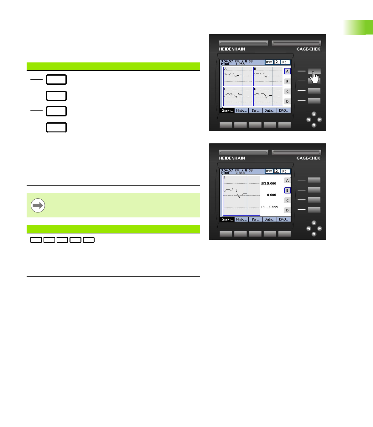
Dimension keys Function
Pressing a dimension key in the:
DRO screen: performs the function
assigned in the hotkey setup
screen. By default no hotkey
function is assigned until the user
makes the assignment
Graph screens: displays a single
graph for the corresponding
dimension
Bar screens: Displays a single bar
showing current values for the
corresponding dimension
Data screens: displays a single data
table of stored values for the
corresponding dimension
Hot key assignments are discussed in detail on page 141.
1.3 Panel key descriptions
Soft keys Function
Soft keys initiate functions that are
labeled above the keys at the bottom
of the LCD screen. As different
system functions are selected, the
soft key labels change in support of
those functions.
ND 2100G GAGE-CHEK 23
Pressing the dimension A key in a graph screen
selects the A graph for display.
Page 24
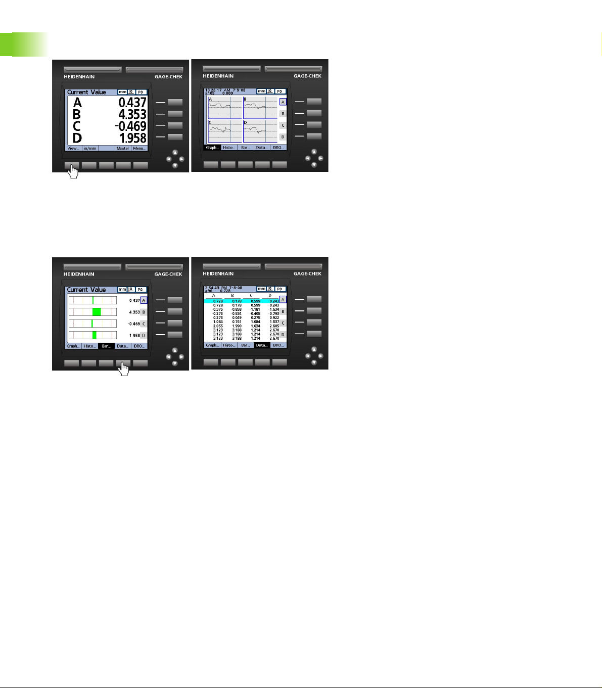
Pressing the VIEW... soft key changes soft key labels to show five
screen viewing options, graph, histogram, bar, data and DRO.
Pressing the VIEW... soft key causes soft key labels to change,
offering five options for viewing data.
When viewing graphs of stored data, current value bars or tables of
1.3 Panel key descriptions
stored data, pressing a different soft key changes to the view
indicated by the soft key label.
Pressing the DATA... soft key when viewing bars causes the
dimension data table to be displayed.
24 1 Operation
Page 25
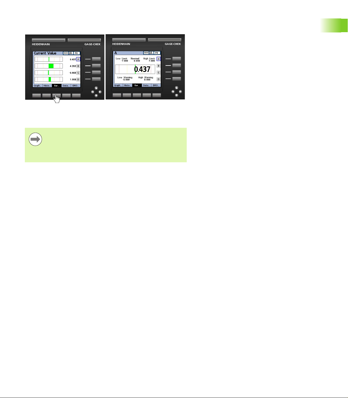
Pressing the currently highlighted soft key alternates between singledimension and multiple-dimensions displays.
Pressing the BAR... soft key when viewing multiple-dimensions
causes the currently selected dimension to be displayed by itself.
The left most soft keys can be designated hotkeys to
provide quick access to commonly used functions when
the home screen is displayed. Hot key assignments are
discussed in detail in Chapter 2: Installation, Setup and
Specifications.
1.3 Panel key descriptions
ND 2100G GAGE-CHEK 25
Page 26
1.4 LCD screens and menus
The ND 2100G LCD presents a variety of screens and menus selected
by the user to display current dimension values, pass fail test results,
dimension value graphs, statistical process control graphs and data
tables, and setup and part configuration options.
Screen navigation
ND 2100G screen navigation is straightforward. For example, to
display a bar graph of current values from the home screen, press the
MENU... soft key, then press the VIEW... soft key and then the BAR...
soft key.
1.4 LCD screens and menus
Press the VIEW... soft key then the BAR... soft key.
26 1 Operation
Page 27
Home screen
The home screen is displayed after the startup screen when power is
applied to the ND 2100G, and is displayed after the FINISH key is
pressed to complete a measurement or screen evaluation.The default
home screen is the DRO, but can be reassigned to another screen in
the Display setup screen.
The assignment of the home screen is discussed in detail
in Chapter 2: Installation, Setup and Specifications.
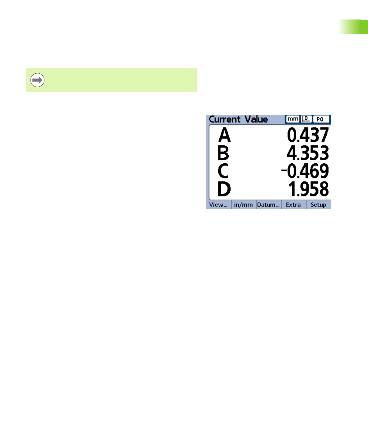
DRO screen
The DRO screen is the default home screen displayed after power is
applied and the startup screen is shown.The DRO screen provides
numeric displays of the current values of up to four dimensions. The
unit of measure, current datum and current part number or part name
are displayed in the upper right corner of the screen.
Use the arrow cursor keys to scroll dimensions when more than four
dimensions are active.
1.4 LCD screens and menus
DRO screen
ND 2100G GAGE-CHEK 27
Page 28
View soft keys and screens
View soft keys for subgroups of one
Pressing the VIEW... soft key when using subgroups of one, changes
soft key labels to show five screen viewing options. Graph, histogram,
bar, data and DRO.
View soft keys Function
GRAPH... Displays data in a line graph
HISTO... Displays data in a histogram
BAR... Displays data in a bar graph
DATA... Displays numerical data
DRO... Displays the DRO screen
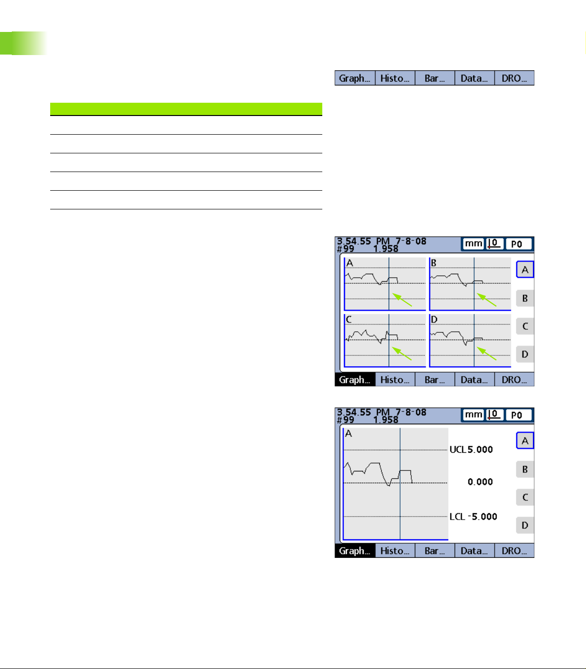
Dimension graphs for SPC subgroups of one
1.4 LCD screens and menus
The dimension graph screen is displayed for SPC subgroups of 1, and
displays graphs for up to 16 dimensions.
Press the GRAPH... soft key to change the number of graphs
presented on the screen. Press a dimension soft key to display a graph
of the dimension and the minimum additional dimensions. Use the
arrow cursor keys to scroll the graphs when more data is stored than
will fit on the screen.
Individual samples are selected by a vertical line on the graph. Move
the vertical line left and right through the stored data using the arrow
cursor keys. The time and date that the selected sample was stored
are shown in the upper left corner of the screen. The ID number of the
sample for the dimension and the value of the data are also shown in
the upper left corner. Displays of a single dimension also show the
nominal and control limit values.
View soft keys for subgroups of one.
Vertical selection lines.
Dimension line graphs for subgroups of one.
28 1 Operation
Page 29
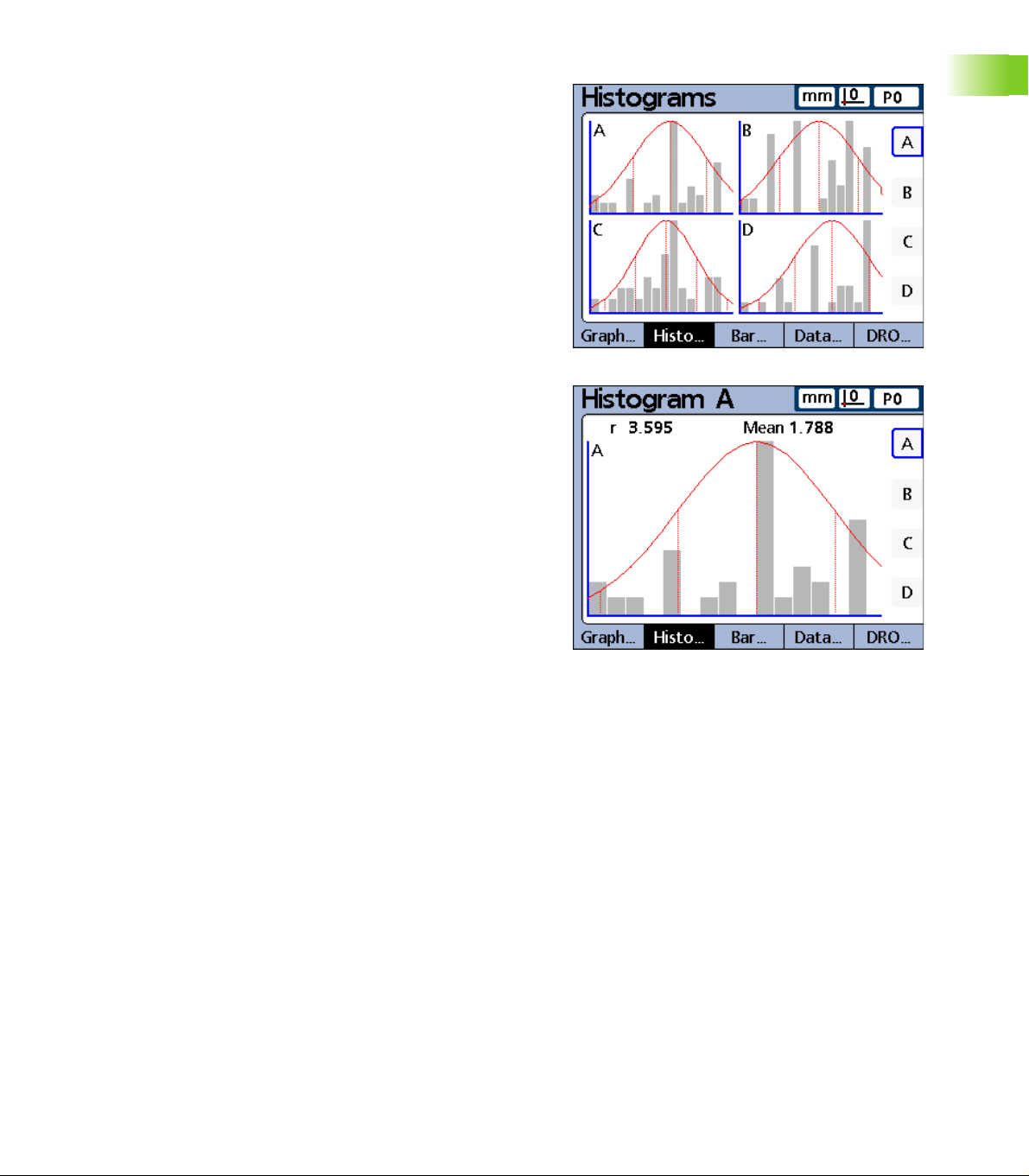
Dimension histograms for SPC subgroups of one
The dimension histogram screen displays histograms of values for up
to 16 dimensions. The dimension histogram screens are displayed for
SPC subgroups of one.
Press the HISTO... soft key to change the number of histograms
presented on the screen. Press a dimension soft key to display the
histogram of a single dimension.
The display of a single dimension also shows the total range and mean
of the values.
1.4 LCD screens and menus
Dimension histograms for subgroups of one.
ND 2100G GAGE-CHEK 29
Page 30
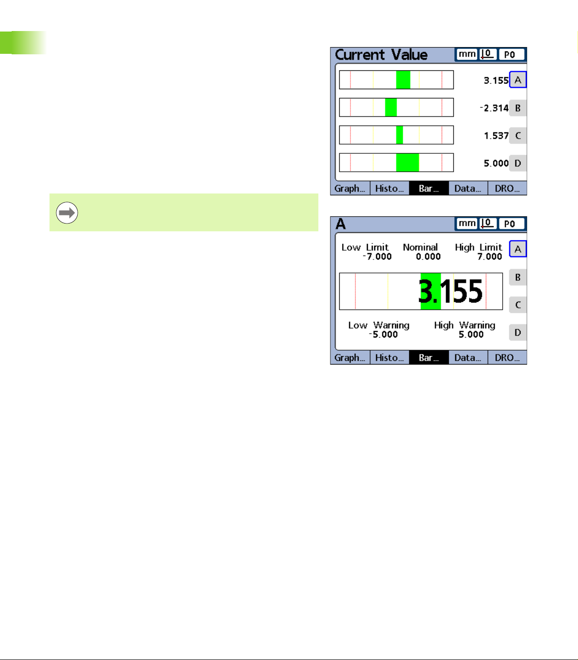
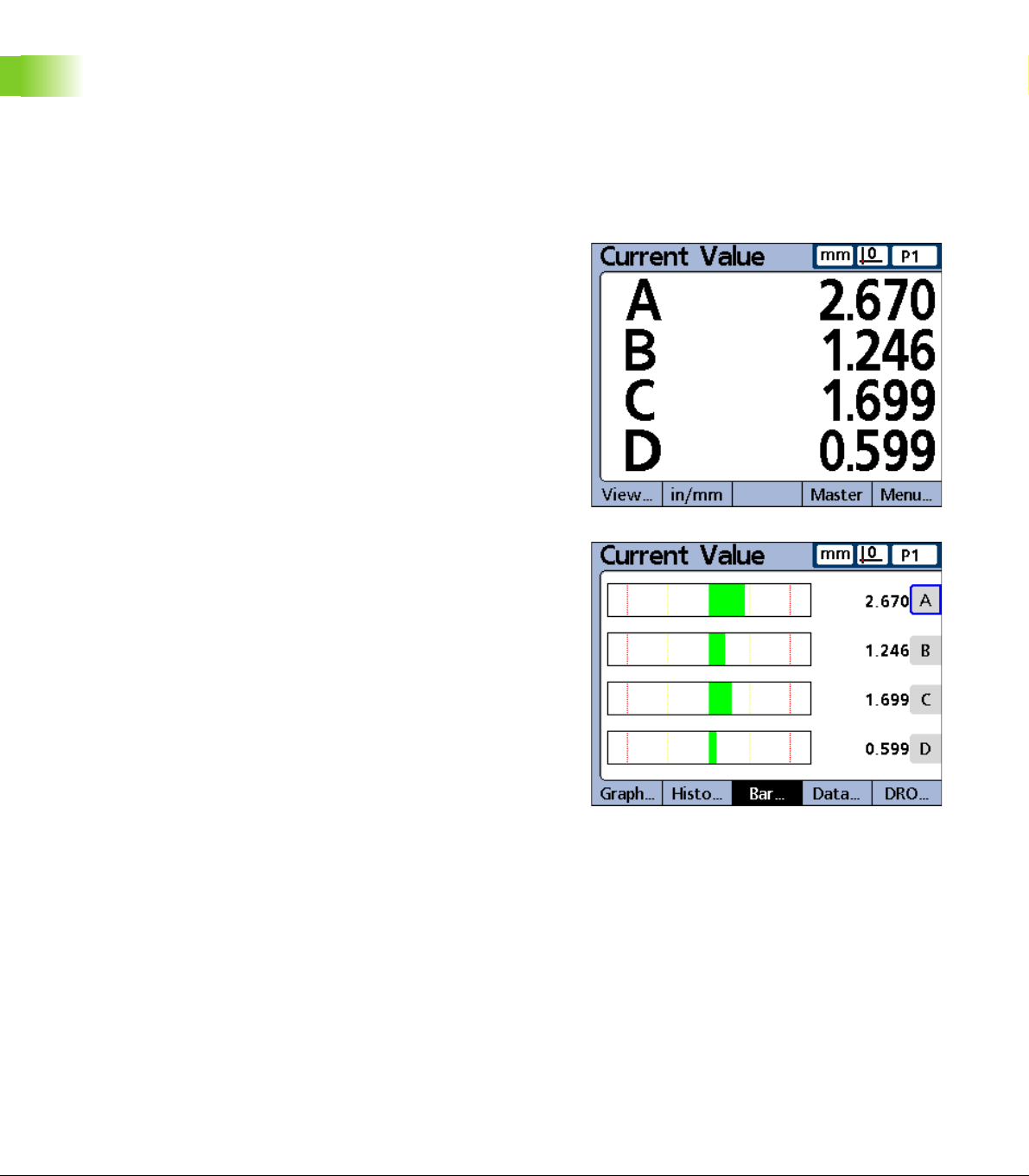
Bar and dial current value displays
The bar and dial screens provide graphic displays of the current values
of up to 16 dimensions. The default bar screen can be configured to
display current value bars in horizontal or vertical orientation using the
Display setup screen.
Bar displays of multiple dimensions show current values. Bar displays
of single dimensions include the current value, nominal value, and high
and low warning and limit values.
Press the BAR... soft key to change the number of bars presented on
the screen. Press a dimension soft key to display a bar for a single
dimension.
The display can be configured in the Display setup screen to include a
dial in addition to the bars. When the dial display is also available, press
the BAR... soft key to toggle between the bars and the dial.
The display of a single dimension can be configured to be
a bar or a dial, but cannot be toggled between a single bar
and a single dial.
1.4 LCD screens and menus
Bar graphs for subgroups of one.
30 1 Operation
Page 31

Dimension data tables for SPC subgroups of one
Dimension data screens contain measurement data stored for up to 4
dimensions. Press the DATA... soft key to toggle between views of
data for all dimensions and data for a single dimension that includes
SPC statistics.
Press a dimension soft key to display data for a single dimension. Use
the arrow cursor keys to scroll the tables when more data is stored
than will fit on the screen.
1.4 LCD screens and menus
Dimension data tables for subgroups of one.
ND 2100G GAGE-CHEK 31
Page 32

View soft keys for subgroups greater than one
Pressing the VIEW... soft key, when using subgroups greater than
one, changes soft key labels to show five screen viewing options. x
Bar, Data and DRO.
View soft keys Function
... Displays the mean (x) of each subgroup for up
x
r... Displays the range ( r ) of each subgroup for
BAR... Displays data in a bar graph
DATA... Displays numerical data
DRO... Displays the DRO screen
to 16 dimensions
up to 16 dimensions
, r,
VIEW soft keys for subgroups greater than one.
Dimension x
1.4 LCD screens and menus
For SPC subgroups greater than 1, the dimension x
in place of the dimension graph screen discussed earlier. The
dimension x screen graphs the mean (x) of each subgroup for up to 16
dimensions.
Press the x
the screen. Press a dimension soft key to display a graph of a single
dimension.
Use the arrow cursor keys to scroll the graphs when more data is
stored than will fit on the screen.
Individual subgroups are selected by a vertical line on the graph. Move
the vertical line left and right through the stored data using the arrow
cursor keys. The time and date when the selected subgroup data was
stored are shown in the upper left corner of the screen. The ID number
of the subgroup and the value of the data for the dimension are also
shown in the upper left corner. Displays of single dimensions also
show the control limits.
charts for subgroups greater than one
screen is displayed
... soft key to change the number of graphs presented on
Vertical line.
charts for subgroups greater than one.
x
32 1 Operation
Page 33

Dimension r charts for subgroups greater than one
For SPC subgroups greater than 1, the dimension r screen is displayed
in place of the Histogram screen discussed earlier. The dimension r
screen graphs the range ( r ) of each subgroup for up to 16 dimensions.
The range is not recalculated for each measurement, but is
recalculated each time a subgroup is completed. Refer to "SPC setup
screen" on page 91.
Use the arrow cursor keys to scroll the graphs when more data is
stored than will fit on the screen.
Individual subgroups are selected by a vertical line on the graph. Move
the vertical line left and right through the stored data using the arrow
cursor keys. The time and date when the selected subgroup data was
stored are shown in the upper left corner of the screen. The ID number
of the subgroup and the value of the data for the dimension are also
shown in the upper left corner. Displays of single dimensions also
show the range control limits.
1.4 LCD screens and menus
r charts for subgroups greater than one.
ND 2100G GAGE-CHEK 33
Page 34

Dimension data tables for subgroups greater than one
Dimension data screens display measurement data for up to 4
dimensions. The Data screen for a single dimension is slightly
different for SPC subgroups greater than 1 than those for SPC
subgroups of 1. Individual subgroups are indicated by a horizontal line
in tables for single dimensions. The data table for multiple dimensions
remains unchanged for SPC subgroups greater than 1.
Press the DATA... soft key to toggle between views of data for all
dimensions and data for a single dimension that includes SPC
statistics. Press a dimension soft key to display data for a single
dimension.
Use the arrow cursor keys to scroll the tables when more data is
stored than will fit on the screen.
The time and date when the highlighted subgroup data was stored are
shown in the upper left corner of the screen. The ID number of the
data record and the value of the data for the dimension are also shown
in the upper left corner.
1.4 LCD screens and menus
Dimension data tables for subgroups greater than one.
34 1 Operation
Page 35

in/mm menu items
Press the IN/MM soft key to toggle the display between inch and
millimeter units of measure. This does not alter the channel
configurations in the Channel setup screen. The ND 2100G calculates
the conversion from one unit of measure to another as a convenience
to the user.
Master menu items and screens
Master screens are used to calibrate the encoder datums or
transducer input channel ranges. The Master function is configured in
the Master setup screen to either calibrate datum D0 for encoders, or
calibrate datum D0 and the entire channel range for transducers.
Prior to applying, and after clearing a mastered channel
value, the ND 2100G machine zero is used as the absolute
datum.
Master screen for calibrating encoder datums
When the Master setup screen is configured to perform full
calibrations of transducer input channels (Master type set to MinMax), the full range of any channel input can be calibrated at any time
using the Master function Min and Max screens. Up to 18 range
calibration values can be stored for each ND 2100G transducer input
channel. Any of these groups can be quickly recalled and applied later.
Instructions for calibrating channel datums are provided
later in this chapter.
1.4 LCD screens and menus
Pressing the MASTER soft key brings up the Channel
Master screen for calibrating encoder datums.
ND 2100G GAGE-CHEK 35
Page 36

Master screen for calibrating transducer ranges
When the Master setup screen is configured to perform full
calibrations of transducer input channels (Master type set to MinMax), the full range of any channel input can be calibrated at any time
using the Master function Min and Max screens. Up to 18 range
calibration values can be stored for each ND 2100G transducer input
channel. Any of these groups can be quickly recalled and applied later.
Instructions for calibrating transducer input channels Min
and Max range values are provided later in this chapter.
1.4 LCD screens and menus
Master Min screen for calibrating transducer range.
Master Max screen for calibrating transducer range.
36 1 Operation
Page 37

Menu soft keys
Pressing the MENU... soft key changes soft key labels to show Menu
options: View..., in/mm, Datum..., Extra and Setup.
Menu soft keys Function
VIEW... Pressing the VIEW... soft key provides
access to View menu options. Refer to "View
soft keys and screens" on page 28.
IN/MM Pressing IN/MM soft key toggles between
inch and millimeter units of measure for
applicable dimensions. Refer to "in/mm menu
items" on page 35.
DATUM... Pressing the DATUM... soft key provides
access to Datum menu options.
EXTRA Pressing the EXTRA soft key provides access
to Extra menu options.
SETUP Pressing the SETUP soft key provides access
to Setup menu options.
The datum menu functions
The DATUM... functions provide the means to ZERO, PRESET, CLEAR
and toggle between measurement reference datums.
Datum soft keys Function
D0/D1 Pressing the D0/D1 soft key toggles between
the absolute datum (D0) and the incremental
datum (D1).
Menu soft keys.
1.4 LCD screens and menus
Datum soft keys.
ZERO... The Zero menu function can be used at any
time to simultaneously zero all incremental
datums, or to zero any specific incremental
datum.
MASTER The Master functions are used to calibrate
PRESET The Dimension Preset screen is used to
CLEAR The Clear menu function can be used at any
ND 2100G GAGE-CHEK 37
the encoder datums or transducer input
channel ranges.
preset incremental datums.
The incremental datum of a dimension can be
preset to a specific value at any time by
pressing the PRESET soft key, pressing a
dimension soft key and entering the desired
value.
time to simultaneously clear all incremental
datums. Cleared incremental datums (D1) are
made equal to absolute datums (D0).
Page 38

The Extra menu functions
The Extra menu provides quick access to a variety of display and other
system functions. To use any Extra menu function, highlight the
desired function, and then press the ENTER key.
Extra menu
functions
Cycle Advances to the next defined part. Part
DMS/DD Toggles the display of angles between
Fast3 Refer to "Fast3" on page 39.
Hold Toggle function that holds (freezes) or
1.4 LCD screens and menus
Part? Displays a pop-up screen that allows the user
Rad/Dia Toggles between the radius and diameter
Recall Applies the last used incremental datum (D1)
RsetDyn Resets the minimum and maximum values
Function
numbers are cycled in a continuous loop.
Degrees, Minutes, Seconds (DMS) and
Decimal Degrees (DD).
releases the current value of a single
dimension when a dimension soft key is
pressed, or of all dimensions when the ALL
soft key is pressed.
to specify a new part number.
measurement types on the DRO screen, if
radius or diameter was specified in the
Formats setup screen.
preset that was entered by the user.
accumulated during dynamic measurements.
This function must be initiated prior to new
dynamic measurements.
EXTRA menu functions.
Send Sends the specified current dimension
values, or all current dimension values to the
RS-232 serial port for transmission to a
computer. The user is prompted to send one
or all.
SendRec Sends stored records to the RS-232 serial
port for transmission to a computer. Refer to
"Report setup screen" on page 127.
38 1 Operation
Page 39

Fast3
Channel input
values stored
Channel input
values stored
Channel 2
input value
Sample
increment
X-Axis (ch 1)
Y-Axis
(ch 2)
High
limit
Low
limit
The Fast3 function samples the channel 2 input each time the channel
1 input changes a specified sample increment. If the sampled value of
channel 2 falls outside a specified range, all base-channel (first 1, 4 or
8 channels) input values will be stored in a dedicated memory array,
otherwise samples will not be stored.
This sampling process continues until:
The user aborts the process by pressing the QUIT or the CANCEL
key
The user clears memory and restarts the process by pressing the
ENTER key
The user successfully completes the process by pressing the
FINISH key
The process is automatically completed after 50,000 sets of channel
positions have been stored
For the duration of the Fast3 function process, the
ND 2100G adopts an X-Y axis paradigm. Channel 1 is
referred to as the X-axis, and channel 2 as the Y-axis.
In the example shown, the channel 2 (Y-axis) input values exceed the
user-specified limits five times, but channel input values are stored
only twice when the channel 2 value exceeds the limits at a sample
point between intervals.
1.4 LCD screens and menus
ND 2100G GAGE-CHEK 39
Page 40

When the Fast3 function is successfully completed, the stored sets of
channel input values are processed by the ND 2100G dimension
formulas in the order that they were collected. The formula results are
then stored in the ND 2100G database. During the processing of
formulas, a percentage of completion will be displayed. Since up to
50,000 sets of channel input values can be collected and processed by
formulas, considerable time could be required to complete the
processing.
Since the values processed by formulas after Fast3 data
collection are contained in memory storage, no user
interaction is possible. For this reason functions that
require user interaction such as the Ask function must be
avoided in formulas when the Fast3 Extra menu function
is used.
If any key is pressed while the ND 2100G is processing
formulas, the remaining channel input values will be
deleted from memory and formula processing will be
1.4 LCD screens and menus
aborted.
To access the Fast3 function:
U Press the MENU... soft key
U Press the EXTRA soft key
U Use the arrow cursor keys to highlight Fast3
U Press the ENTER key
You will then be prompted to:
U Enter a Y axis (channel 2) upper limit
U Enter a Y axis (channel 2) lower limit
U Enter an X axis (channel 1) capture increment
U Enter an X axis (channel 1) resolution factor (this is a multiplier of
scale resolution)
Once these parameters are entered, the Fast3 function will begin to
read the input values for channels 1 and 2.
FAST3 highlighted.
Setup menu functions
ND 2100G operating parameters and formulas that define dimension
values are entered into the system from Setup menu screens.
Setup menu functions and formulas and are discussed in
Chapter 2: Installation, Setup and Specifications
40 1 Operation
Page 41

1.5 Operating instructions
Basic operation of the ND 2100G is illustrated by the typical process
steps below.
Select Part Establish a
Measurement
Reference
Specify part
number
Measurement steps and the resulting data collected depend entirely
on setup parameters and dimension formulas defined to satisfy a
specific application.
Examples used in this chapter use encoder probes to
emphasize concepts. However, the concepts apply
equally well to all types of input devices.
Absolute datum
(D0)
• Hard stop zero
• Set datum
• Calibrate datum
and range
Incremental datum
(D1)
• Zero datum
• Preset datum
Conduct a
Measurement
Manual:
• Probe & Enter
Sequence:
• Series of probes
& Enters
Dynamic:
• Probe samples &
Enter
Semi-automated:
• Probe &
automatic Enter
Review
Measurement
Data
SPC Subgroup = 1
• Dimension graphs
Histograms
• Dimension data
tables
• SPC data
SPC Subgroups > 1
• x
graphs
• r graphs
• Dimension data
tables
• SPC data
Report or Send
Results
Print reports
Send data to
computer
1.5 Operating instructions
ND 2100G GAGE-CHEK 41
Page 42

Select a part to begin a measurement
The correct part (number) must be selected prior to conducting
measurements.
Select Part Establish a
Measurement
Conduct a
Measurement
Reference
One hundred part configurations can be stored in the ND 2100G. Each
part configuration includes all the ND 2100G settings and dimension
formulas required to conduct measurements and report results for the
part.
To select a part:
U Press the MENU... soft key
U Press the EXTRA soft key
1.5 Operating instructions
U Use the arrow cursor keys to highlight Cycle or Part?
U Press the ENTER key. If Part? was highlighted, you will be prompted
for a part number.
U Use the numeric keypad to specify the part
U Press the ENTER key
If Cycle was highlighted, the part number will be incremented.
Continue incrementing to select the desired part number.
Review
Measurement
Data
Cycle highlighted.
Report or Send
Results
Part? highlighted.
42 1 Operation
Page 43

Establish a reference for the measurement
A measurement reference should be established prior to conducting
measurements. Measurement references can be established by
calibrating channels or presetting dimensions.
Select Part
An input calibration is applied to any parts that use that
channel in a formula. For example, a channel calibration
performed for channel 1 and part number 0 will also apply
to any other parts using channel 1.
Calibrating channels using the Master function
Channel calibrations are performed using the Master function. A
single-point calibration defines the reference value of the absolute
datum (D0) of an input channel. A full calibration defines the reference
value of the absolute datum, and the resolution of the channel input.
Since encoders have fixed resolutions based on etched scales or
some other permanent device characteristic, typically only a single
point is calibrated to define a reference position. Transducers such as
LVDT and Half-bridge devices do not have fixed resolutions. The use
of these devices requires calibrating both ends of the transducer’s
measurement range to derive resolution. Once a full calibration has
been performed, single-point calibrations can be performed as
required to define new measurement reference positions.
Establish a
Measurement
Reference
Conduct a
Measurement
Review
Measurement
Data
Report or Send
Results
1.5 Operating instructions
ND 2100G GAGE-CHEK 43
Page 44

Calibration of a single reference point
A single measurement reference point can be calibrated for encoders
and fully-calibrated transducers.
The Master type should be set to Mean in the Master
setup screen to perform a calibration of a single encoder
point. Refer to "Master setup screen" on page 111.
To calibrate a single reference point
U Press the MASTER soft key
U Use the arrow cursor keys to select the desired channel
U Position the probe against the reference surface
U Use the numeric keypad to enter the reference value (zero or the
desired offset) into the Master Value data field
U Press the ENTER key
U Press the YES soft key to calibrate the measurement reference
1.5 Operating instructions
A green dot will appear next to the actual value indicating that the
reference point is calibrated.
Channel 1 selected. Reference value of 0.
Press the YES soft key.
Channel 1 calibrated.
44 1 Operation
Page 45

Calibration groups (G1, G2, G3...G18)
All calibration values shown on the screen are simultaneously applied
when the ENTER key is pressed. While this is acceptable in most
cases, some applications require entering a series of calibrations at
different times. The example shown here illustrates this difference.
When measuring runout at two points on a
rod, both channels are measuring a
common surface and can be calibrated
simultaneously. In this example, both
channels are calibrated to zero on the rod
surface in calibration group 1 (G1).
Completed calibrations are indicated by
filled circles at the right of the actual channel
values.
When measuring the low and high lifts of
two offset cams, simultaneous calibration
on the offset surfaces is not possible. First
one channel must be calibrated to zero on
the low surface of one cam, then after
turning the cam shaft 90 degrees, the
second channel must be calibrated to zero
on the low surface of the second cam.
The first calibration is performed in
calibration group 1 (G1), then the camshaft
is turned 90 degrees, and the second
calibration is performed in calibration group
2 (G2). By performing the calibrations in
different groups, the calibrations are made
independent. Completed calibrations are
indicated by filled circles at the right of the
actual channel values.
Calibrating two points on a rod.
1.5 Operating instructions
Calibrating offset surfaces Master G1.
Calibrating offset surfaces Master G2.
ND 2100G GAGE-CHEK 45
Page 46

Calibrations of transducer resolution (Min-Max calibrations)
Transducers such as LVDT and half bridge devices do not have fixed
resolutions based on etched scales or other permanent device
characteristics. The use of these devices requires calibrating both
ends of the transducer range of measurement to derive transducer
resolution. Full transducer calibrations are performed periodically on a
schedule determined by your application using the Master function.
Full calibrations are performed only after performing the transducer
gain and null setup steps described in Chapter 2: Installation, Setup
and Specifications.
The Master type should be set to Min-Max in the Master
setup screen to perform a full transducer calibration. Refer
to "Master setup screen" on page 111.
To perform a full transducer calibration:
1.5 Operating instructions
Calibrate minimum level:
U Press the MASTER soft key
U Press the MIN soft key to display the Master Min screen
U Use the arrow cursor keys to select the desired channel
U Press the G1, G2...G18 soft key to select a group to store the
calibration data in. Refer to "Calibration groups (G1, G2, G3...G18)"
on page 45.
U Position the channel’s probe against the measurement Min
reference surface
U Use the numeric keypad to enter the Min reference value into the
Master Value data field for the channel
U Press the ENTER key
U Press the YES soft key to set the Min value or offset the absolute
datum (D0) for the channel. This calibrates the low end of the
channel measurement range.
The completed minimum level calibration will be indicated by a filled
green circle in the Mn column at the right of the Actual channel value.
Completed minimum level calibration.
46 1 Operation
Page 47

Calibrate maximum level:
U Press the MAX soft key
U Use the arrow cursor keys to select the same channel as in step 1
if necessary
U Position the channel probe against the measurement Max reference
surface for the maximum end of the channel calibration range
U Use the numeric keypad to enter the Max value into the Master
Value data field for the channel
U Press the ENTER key
U Press the YES soft key to calibrate the maximum value for the
channel input
The completed maximum level calibration will be indicated by a filled
green circle in the Mx column at the right of the Actual channel value.
Completed maximum level calibration.
1.5 Operating instructions
ND 2100G GAGE-CHEK 47
Page 48

Establishing a temporary dimension reference
Establishing a temporary dimension reference is useful when quick
point to point measurements are desired. The temporary reference is
only applied to the associated dimension, and only to the current part.
For example, a temporary reference established for dimension A and
part number 0 will not apply to any dimensions or to any other parts
that might include their own dimension A.
Temporary dimension references can be established for encoders and
transducers. Since only one point is used as a reference, transducer
resolution remains unchanged.
Dimension references can be zeroed or preset to specific values.
Zeroing a dimension reference
Dimensions can be zeroed at any time using the Datum/Zero function.
The zero reference is temporary in the sense that it uses the
incremental datum D1, and has no effect on the absolute datum D0.
1.5 Operating instructions
To zero a dimension:
U Press the MENU... soft key
U Press the DATUM soft key
U Press the ZERO... soft key. The soft keys across the bottom of the
screen will be labeled to support zeroing specific or all dimensions.
U Use the left and right arrow cursor keys to scroll through dimensions
when there are more dimensions defined than ND 2100G soft keys
U Press the desired ZERO key to zero the corresponding dimension
Dimension A prior to zeroing.
Dimension A zeroed.
48 1 Operation
Page 49

Presetting a dimension reference to a specific value
Dimensions can be preset to a user-specified value using the Datum/
Preset function. The reference is temporary in the sense that it uses
the incremental datum D1, and has no effect on the absolute datum
D0.
To preset a dimension reference:
U Press the MENU... soft key
U Press the DATUM soft key
U Press the PRESET soft key. The Select dimensions screen will be
displayed.
U Press the dimension key associated with the dimension you wish to
preset. A text line will be displayed
U Use the numeric keypad to enter the reference value (preset) of the
new reference
U If desired, press the W/NOM soft key to change the nominal value
in the Tolerance setup screen to the new preset reference value
U Press the ENTER key to preset the dimension measurement
reference
Dimension preset text line.
1.5 Operating instructions
Enter the reference value.
Dimension A preset.
ND 2100G GAGE-CHEK 49
Page 50

Clearing channel calibrations
The reference calibrations and full calibrations of all channels can be
cleared using the LCD ON/OFF key.
To clear calibrations:
U Press the LCD ON/OFF key
U Press the CLR CAL soft key
U Press the YES soft key to clear channel mastered values and full
calibrations
Channel mastered values and full calibrations will be cleared, indicated
by the empty circles at the right of the screen. The values will be
retained in the Master values fields, and can be reactivated at any time
by pressing the ENTER key.
1.5 Operating instructions
Press the YES soft key to confirm clearing channel
calibrations.
Empty circles indicate channel mastered values and
full calibrations are cleared.
Clearing dimension references (presets)
Dimension references can be cleared at any time using the Datum/
Clear function.
To clear dimension references:
U Press the MENU... soft key
U Press the DATUM soft key
U Press the CLEAR soft key
U Press the YES soft key to clear dimension preset references. When
a preset reference is cleared, D0 becomes the new reference.
Press the YES soft key to confirm clearing dimension
references.
50 1 Operation
Page 51

Conducting measurements
Once a part number is selected and a reference is established,
measurements can be conducted.
Select Part Establish a
Measurement
Reference
Measurements can:
Be conducted manually, completely under the control of the
operator
Follow a predetermined sequence of steps shown on the screen
Be based on dynamic samples of changing input data
Be semi-automated to increase the throughput of repetitive
measurements
Typically a setup person will configure the ND 2100G for operation in
the Setup screens and then will construct formulas defining
dimensions in the Formula screens described in Chapter 2:
Installation, Setup and Specifications.
Once the ND 2100G is configured and dimension formulas are
constructed, measurement instructions are usually given to the
operator that reflect the specific measurement requirements and gage
equipment setup. Instructions provided in this guide are generic and
meant to be used as guidelines when applying the ND 2100G to
specific measuring applications.
Manual measurements
Manual measurements are performed completely under the control of
an operator. Measurement results can be displayed as current values,
in graphs or in data tables using the screens described earlier in this
chapter. Please refer to the descriptions of Views on page 28.
Measurements can also be printed or transmitted to a computer. The
data printed or transmitted are specified and formatted in the setup
screens described in Chapter 2: Installation, Setup and Specifications.
To conduct manual measurements:
U Probe a single point with one channel, or multiple points
simultaneously with multiple channels
U When the measurement data are displayed on the LCD, press the
ENTER key to store the data
Conduct a
Measurement
Review
Measurement
Data
Report or Send
Results
1.5 Operating instructions
ND 2100G GAGE-CHEK 51
Page 52

Sequential measurements
The ND 2100G can be configured in the Formula setup screen to direct
the user through a sequence of predetermined measurement steps.
Typically a setup person will provide instructions describing how to
conduct the measurements. However, the ND 2100G operation is
fundamentally the same for all sequential measurements.
Measurement results can be displayed as current values, in graphs or
in data tables using the screens described earlier in this chapter.
Please refer to the descriptions of Views on page 28.
Measurements results can also be printed or transmitted to a
computer. The data printed or transmitted are specified and formatted
in the setup screens described in Chapter 2: Installation, Setup and
Specifications.
To perform a sequential measurement:
U Probe the dimension underlined on the DRO screen
U Press the ENTER key to store the data. The underline will advance
1.5 Operating instructions
to highlight the next dimension in the measurement sequence.
U Continue probing the underlined dimensions and pressing the
ENTER key, following the sequence of underlined steps on the LCD
When measurements specified for the part are complete, the
ND 2100G will return to underline the first dimension in the series to
indicate the beginning of a new sequence.
Press the ENTER key to store data and advance to
next dimension.
52 1 Operation
Page 53

Dynamically sampled measurements
The ND 2100G can be configured in the Formula setup screen to
sample input channels and retain the minimum and maximum values
of all samples for each channel. Typically a setup person specifies
dynamic measurements to evaluate rotational or curved surfaces and
will provide instructions describing how to conduct the
measurements. The ND 2100G operation is essentially the same for
all dynamic measurements.
Measurement results can be displayed as current values, in graphs or
in data tables using the screens described earlier in this chapter.
Please refer to the descriptions of Views on page 28.
Measurement results can also be printed or transmitted to a
computer. The data printed or transmitted is specified and formatted
in the setup screens described in Chapter 2: Installation, Setup and
Specifications.
In the example shown here, the runout of a shaft is measured. The
minimum and maximum values are sampled as the shaft is turned.
To perform a dynamic measurement:
U Perform a dynamic reset by pressing the LEFT WIDE key (factory
default), or by highlighting RsetDyn in the Extra menu
U Press the ENTER key to clear old dynamic measurement data prior
to a new measurement
U Position the probe(s) against the surface to be measured
U Rotate or move the surface slowly while observing the resulting
dimension value(s)
1.5 Operating instructions
Measuring the runout of a shaft.
The sampling rate for LVDT, HBT (Half-bridge) and serial
transducers will be slower than for encoders. If your
system includes these input devices, the part must be
rotated or moved slowly to ensure that all points on the
surface are sampled.
U Repeat the rotation or movement until the dimension values that
reflect minimum or maximum values no longer change
U Press the ENTER key to store the measurement data
ND 2100G GAGE-CHEK 53
Page 54

Semi-automated measurements
Normally, measurements shown on the DRO screen are not stored in
the ND 2100G database until the user presses the ENTER key.
However, the ND 2100G can be configured in the Formula setup
screen to perform and store measurements automatically when the
gage is loaded with a new part.
Measurement results can also be printed or transmitted to a
computer. The data printed or transmitted is specified and formatted
in the setup screens described in Chapter 2: Installation, Setup and
Specifications.
In the example shown here, the flatness of a sheet is measured. The
measurement is performed and entered into the database a short time
after the gage is lowered to position the probes against the surface of
the sheet. The channels are reset for a new measurement when the
probes are lifted away from the sheet.
Typically, a setup person specifies semi-automated measurements to
increase the throughput of repetitive measurements, and will provide
1.5 Operating instructions
instructions describing how to conduct the measurements, and load
and unload the gage.
Measurement results can be displayed as current values, in graphs or
in data tables using the screens described earlier in this chapter.
Please refer to the descriptions of Views on page 28.
The instructions for performing semi-automated measurements
depend entirely on the measurement application and equipment
setup, and must be provided by the setup person. Refer to "Trip
function and measurement automation" on page 212 for more details
regarding semi-automated measurements.
Load part: Channels ready
Gage closed: Channels measure
Unload part: Channels reset
54 1 Operation
Page 55

Reviewing measurements
Measurement results can be reviewed in graphs or in data tables using
the screens described earlier in this chapter. Please refer to the
descriptions of Views on page 28.
Select Part Establish a
Measurement
Reference
Conduct a
Measurement
Printing reports or sending results to a computer
Measurement data can be printed or transmitted to a computer. The
report and data transmission formats are prepared in the Header,
Report, Send, Parallel and RS-232 setup screens described in Chapter
2: Installation, Setup and Specifications.
Select Part Establish a
Measurement
Reference
Printing reports
Reports of current dimension values, stored measurement results or
ND 2100G setup parameters can be printed by displaying the desired
screen and pressing the PRINT key. In some cases, the user will be
prompted to provide additional information.
Conduct a
Measurement
Review
Measurement
Data
Review
Measurement
Data
Report or Send
Results
Report or Send
Results
1.5 Operating instructions
ND 2100G GAGE-CHEK 55
Page 56

Sending data to a computer
Current dimension values, or a collection of stored dimension
measurement results can be transmitted to a computer using the
Send and SendRec functions in the Extra menu. Refer to "The Extra
menu functions" on page 38 for more details regarding the Extra
menu.
To send current dimension values:
U Press the MENU... soft key
U Press the EXTRA soft key
U Use the arrow cursor keys to highlight Send
U Press the ENTER key to send the current dimension values to a
computer
To send stored measurement results:
U Press the MENU... soft key
U Press the EXTRA soft key
U Use the arrow cursor keys to highlight SendRec
1.5 Operating instructions
U Press the ENTER key to send a file of stored measurement results
Use Send to send current values.
Use SendRec to send stored measurement values.
56 1 Operation
Page 57

Data reports
Report type Screen User actions
Current dimensions (Numeric display) DRO
U Press PRINT key
Graphs of dimension values
Graph...
(SPC subgroups = 1)
Histograms of dimension values
Histo... U Press PRINT key
(SPC subgroups = 1)
chart of subgroup mean values
x
x chart U Press PRINT key
(SPC subgroups> 1)
r chart of subgroup range values
r chart U Press PRINT key
(SPC subgroups>1)
Current dimension values (Bar display) Bar...
Current dimension values (Dial display) Dial...
Data table multiple-dimensions Data...
Data table single-dimensions Data...
U Press PRINT key
U Press PRINT key
U Press PRINT key
U Press PRINT key
U Respond to prompt
U Press DIMENSION soft key
U Press PRINT key
U Respond to prompt
1.5 Operating instructions
ND 2100G GAGE-CHEK 57
Page 58

Clearing stored measurement data
Stored measurement data can be cleared for a single part, or for all
parts by pressing the LCD ON/OFF key.
Erased data cannot be restored.
To clear stored data for a single part:
U Select the desired part
U Press the LCD ON/OFF key
U Press the CLR PRT soft key
Stored data for the selected part will be erased.
To clear stored data for all parts:
U Select the desired part
1.5 Operating instructions
U Press the LCD ON/OFF key
U Press the CLR ALL soft key
Stored data for all parts will be erased.
58 1 Operation
Page 59

Installation, Setup, Formulas and Specifications
Page 60

2.1 ND 2100G Shipment Contents
The contents of your ND 2100G shipment are described below.
Repackaging instructions are also included for return shipments for
distributors and OEM customers that are configuring an ND 2100G
and shipping it to an end-user.
Save the ND 2100G packaging materials for possible
return shipment or shipment to an end user.
Items included with the ND 2100G
The following items are shipped with the ND 2100G:
ND 2100G instrument
Mounting stand hardware
Power cord
ND 2100G Quick Reference Guide
Warranty registration card
2.1 ND 2100G Shipment Contents
Optional items possibly included
The following items might be shipped with your ND 2100G, depending
on the options and accessories ordered at the time of purchase:
Remote foot switch
Remote keypad
ND 2100G Protective cover
QUADRA-CHEK Wedge communication software
If any components were damaged in shipment, save the
packaging materials for inspection and contact your
shipping agent for mediation. Contact your HEIDENHAIN
distributor or OEM for replacement parts.
60 2 Installation and Specifications
Page 61

Repackaging the ND 2100G
When shipping the ND 2100G on to an end-user, repackage all
ND 2100G components in the original packaging as received from the
factory.
The original packaging must be duplicated and the LCD
must be inserted face-up to prevent damage to the
screen.
It is not necessary to ship the mounting stand and
hardware with the instrument when returning the
ND 2100G for service.
Connect the mounting screws and washer to the ND 2100G
instrument
Replace the contents of the cardboard box insert if shipping the
ND 2100G on to an end-user. The cardboard box can be empty if
returning the ND 2100G to the factory for service.
Repackage the instrument, foam and cardboard box insert as
originally shipped from the factory. The instrument should be
oriented face-up in the carton.
Replace the warranty card and slip sheets originally found at the top
of the carton when shipping on to an end-user. The “Before you
begin” slip sheet should be inserted last.
2.1 ND 2100G Shipment Contents
ND 2100G GAGE-CHEK 61
Page 62

2.2 Hardware Installation
5
4
3
2
1
The ND 2100G is easy to install in a variety of measurement
applications. This section describes how to install the ND 2100G
hardware.
Assembling the mounting stand
The ND 2100G is secured to the swivel slots of the mounting stand by
a shoulder screw, a cap screw and associated washers.
To assemble the ND 2100G to the mounting stand as shown, and then
tighten the cap screw (5) and washers (3 & 4) so that the ND 2100G
will be secure when adjusted to the desired tilt position.
U Tighten the shoulder screw (1)
U Tighten the cap screw (5) and washers (3 & 4) so that the ND 2100G
will be secure when adjusted to the desired tilt position
2.2 Hardware Installation
U Adjust the ND 2100G to the desired tilt position
Benchtop location and mounting
Rest the ND 2100G on a flat, stable surface, or bolt it to a stable
surface from the bottom using four 10/32 screws fastened in the
pattern shown at the right.
The dimensions are shown in millimeters.
Mounting stand assembly.
Mounting hole pattern.
62 2 Installation and Specifications
Page 63

Arm mounting (optional)
Secure the arm mount adapter to the ND 2100G and bolt the adapter
and ND 2100G to the arm as shown at the right.
2.2 Hardware Installation
Optional arm mounting.
ND 2100G GAGE-CHEK 63
Page 64

Connecting power
1
2
1
3
Connect the ND 2100G to power through a high-quality power surge
suppressor. Surge suppressors limit the amplitude of potentially
damaging power line transients caused by electrical machinery or
lightning, and protect the ND 2100G from most power line transients
that can corrupt system memory or damage circuits.
Do not locate the power cord where it can be walked on or will create
a tripping hazard. Connect the 3-wire power plug to only a 3-wire
grounded power outlet.
Never connect 2-wire to 3-wire adapters to the power cord
or remove the third ground wire to fit the plug into a 2-wire
electrical outlet. Modifying or overriding the third-wire
ground creates a safety hazard and should not be
permitted.
2.2 Hardware Installation
The power connector assembly includes:
1 Power switch
2 Fuse compartment
3 Power cord connector
Always disconnect the power cord from the source of AC
power before unplugging it from the ND 2100G power
connector. The AC voltage available at electrical outlets is
extremely dangerous and can cause serious injury or
death.
Power switch, fuse and connector.
64 2 Installation and Specifications
Page 65

Connecting channel inputs
1
Channel input devices are attached to standard interface connectors
or to the RS-232 port on the rear of the ND 2100G. Many device
interfaces are available to match the wide variety of encoder and
transducer devices that can be used with the ND 2100G. The number
and type of channel input connectors will vary depending on the
application. Four standard interface connectors are shown here as
examples.
1 Channel input connections
Connect the channel input devices tightly to their connectors. A
channel number is provided near each connector.
Channel input devices must be configured using the Channels setup
screen. Refer to "Channels setup screen" on page 99
Systems can be configured at the factory to support a combination of
single-channel and multi-channel RS-232 networked input devices.
These configurations can include one of the following:
1, 4 or 8 single-input channels
Up to 16 networked RS-232 input channels
A combination of single-input channels and networked RS-232 input
channels for a total of up to 16 channels
To connect channel input cables:
U Verify that the ND 2100G is off
U Connect the channel inputs tightly to their connectors. If the
connectors include mounting screws, do not overtighten them.
Channel input connectors.
2.2 Hardware Installation
ND 2100G GAGE-CHEK 65
Page 66

Connecting a computer
1
1
2
Measurement result data can be sent to a computer over the RS-232
port (1) using a serial cable that does not include crossed wires.
To connect a computer:
U Verify that the ND 2100G and the computer power are off
U Connect a computer COM port to the ND 2100G RS-232 serial port
(1) using a standard straight-through serial cable. Make sure the
cable connectors are tight, but do not overtighten the connector
screws.
U Apply power to the computer, and then the ND 2100G. The
ND 2100G default settings for communication over the RS-232
serial port (1) are:
Baud rate 115,200
Word length 8 bits
2.2 Hardware Installation
Stop bits 1 bit
Parity None
U Launch the computer application that will be used to communicate
with the ND 2100G, and configure the communication properties of
the COM port to match those of the ND 2100G
Connecting headphones and USB printer
Connecting headphones
Audio alerts can be sent to headphones in areas that are noisy and
make it difficult to hear, or are quiet where audio alerts might create a
disturbance.
The speaker jack (1) is located on the side of the ND 2100G.
To connect headphones:
U Verify that the ND 2100G power is off. Plug the headphones into the
speaker jack (1) on the side of the enclosure.
U Make sure the headphone plug is fully inserted
RS-232 connector.
Connecting a USB printer
The ND 2100G supports certain USB printers. Printer models are
specified by HEIDENHAIN at the time of purchase, or approved by
HEIDENHAIN later.
The USB port (2) is located on the side of the ND 2100G.
To connect the USB printer:
U Verify that the ND 2100G and printer power are off. Connect the
Headphone and USB connectors.
USB printer to the USB Type A port (2) on the side of the enclosure.
U Make sure the USB cable plug is fully inserted
66 2 Installation and Specifications
Page 67

Connecting an optional foot switch or remote
1
2
keypad
The optional foot switch and remote keypad are connected to the
RJ-45 connector (1) on the side of the ND 2100G.
Often, only the optional foot switch or remote keypad is used.
However, two options can be connected simultaneously using a RJ-45
splitter (2).
RJ-45 splitters are available from most retail electronics
stores.
The foot switch and remote keypad can be used individually or in
combination:
foot switch
foot switch and remote keypad
When the foot switch and remote keypad are connected using the
RJ-45 splitter (2), all operating functions of each device are retained.
However, the switch shares Hot Key mapping with the number keys
7 and 8 of the remote keypad. As a result, functions assigned to the
two switch contacts will also be mapped to remote keypad numbers
7 and 8.
Refer to "Hot Keys setup screen" on page 141.
2.2 Hardware Installation
RJ-45 connector and RJ-45 splitter.
To connect the foot switch or remote keypad:
U Verify that the ND 2100G is off
U Plug an RJ-45 splitter (2) into the ND 2100G RJ-45 connector (1) if
multiple devices will be used
U Connect the RJ-45 plug of the devices into the RJ-45 splitter (2) if
multiple devices will be used, or directly into the ND 2100G RJ-45
connector (1) if only a single device will be used
Optional foot switch and remote keypad.
ND 2100G GAGE-CHEK 67
Page 68

2.3 Software setup
The operating parameters of the ND 2100G must be configured prior
to using the system for the first time, and any time part measurement,
reporting or communication requirements change. Day to day use of
the ND 2100G does not require reconfiguration of system settings.
Parameter changes made in any of the setup screens can
change the operation of the ND 2100G. For this reason
critical setup parameters are password protected. Only
qualified personnel should be given password access to
setup screen parameters. Refer to "Supervisor setup
2.3 Software setup
Software can be configured manually using the Setup menu screens,
or automatically by loading a settings file saved after a previous setup
session. Settings files are loaded from USB drives.
Parameters configured in setup screens will be retained until:
The data-backup battery is changed
The data and settings are cleared by maintenance personnel
Parameters are changed using the Setup menu screens
Certain software upgrades are performed
Previously saved settings files are loaded
screen" on page 161 for unlocking of password protected
setup functions.
68 2 Installation and Specifications
Page 69

Setup menu
1
2
3
Most operating parameters of the ND 2100G are configured using
screens and data fields accessed from the Setup menu. Highlighting
Setup menu items (1) on the left side of the setup screen displays the
corresponding setup parameter data fields (3) and choice fields(2) on
the right side of the screen.
Setup menu features:
1 Setup menu item: Setup screen name
2 Setup choice field: Setup choices are made
3 Setup data field: Setup data are entered
2.3 Software setup
Setup screen menu items, data fields and choice
fields.
ND 2100G GAGE-CHEK 69
Page 70

Accessing and navigating the Setup menu
To access the Setup menu:
U Press the MENU... soft key
U Press the SETUP soft key. The Setup menu is displayed.
2.3 Software setup
Press the MENU... soft key then press the SETUP soft key to display the Setup menu.
To navigate the Setup menu:
U Use the up and DOWN ARROW cursor keys to scroll through the
Setup menu screens
U Use the RIGHT ARROW cursor key to access setup screen menu
items
U Use the UP and DOWN ARROW cursor keys to scroll through and
select a menu item
Pressing the DOWN ARROW cursor highlights next menu item, then pressing the RIGHT ARROW cursor highlights top screen
parameter.
70 2 Installation and Specifications
Page 71

Using dimension keys in the setup mode
1
2
3
4
The functions of the dimension keys change to speed setup screen
navigation when the Setup menu is displayed. Dimension keys can be
used to move to the top or bottom of the Setup menu or to page up
or down through the Setup menu as shown here.
Setup mode function
1 Menu top
2 Page up
3 Page down
4 Menu bottom
Entering data into setup fields
Enter numbers into the highlighted setup screen fields using the
numeric keypad.
Highlight a setup field and use the numeric keypad to enter a number.
The Alpha Entry screen will be displayed when alpha character entry
is required. Enter alpha characters into the Alpha Entry screen by
highlighting a letter and then pressing the ENTER key. Once all desired
characters have been entered press the FINISH key to complete the
entry.
Dimension keys.
2.3 Software setup
Highlight a character then press the ENTER key to enter the character.
ND 2100G GAGE-CHEK 71
Page 72

Deleting data entries
1
3
4
2
Press the CANCEL key to erase the last (right-most) numeric digit or
alpha character in the selected data field.
2.3 Software setup
Highlight a data field and press the CANCEL key to erase the right-most digit or
character.
Entering setup parameters
Setup parameters and functions are displayed above the soft keys
across the bottom of the screen.
Changing the channel or dimension number
Often setup parameters and functions are related to specific channels
or dimensions. When a channel or dimension is highlighted on the
setup screen, the channel or dimension number can be increased or
decreased by pressing the INC or DEC soft key or by pressing the
LEFT or RIGHT WIDE key.
Key Function
1 LEFT WIDE key Decreases the channel or dimension.
2 RIGHT WIDE key Increases the channel or dimension.
3 DEC soft key Decreases the channel or dimension.
4 INC soft key Increases the channel or dimension.
72 2 Installation and Specifications
Page 73

Entering parameters
1
2
When a setup parameter field (1) is highlighted, setup alternatives are
shown above the soft keys across the bottom of the screen (2). Press
the soft key under the desired setup alternative to enter the
parameter.
Parameters and options are shown here:
1 Highlighted parameter field
2 Parameter alternatives
Copying parameters to other parts, dimensions or channels
A single highlighted parameter or all parameters of the current part,
dimension or channel can be copied to all others by pressing the
APPLY ALL soft key.
If all part, dimension or channel parameters are already the same for
the selected setup category, the APPLY ALL soft key will be grayedout.
2.3 Software setup
Copy all parameters by pressing the
APPLY ALL soft key when the part,
dimension or channel name is
highlighted.
ND 2100G GAGE-CHEK 73
Copy a single parameter by pressing the
APPLY ALL soft key when only a single
parameter is highlighted.
Page 74

Saving a parameter and advancing to the next
Press the ENTER key to save the highlighted value and advance to the
next parameter.
2.3 Software setup
Press the ENTER key to store the highlighted value and advance to the next
parameter.
Saving a parameter and returning to the Setup menu
Press the FINISH key to store the value and return to the Setup menu.
Press the FINISH key to store the highlighted value and return to the Setup menu.
Discarding changes and returning to the Setup menu
Press the QUIT key to return to the Setup menu on the left half of the
screen without saving changes.
Press the QUIT key to discard changes and return to the Setup menu.
74 2 Installation and Specifications
Page 75

Leaving the Setup menu
Press the FINISH key repeatedly to conclude the setup session and
return to the home screen.
Press the FINISH key repeatedly to leave the Setup menu and return to the home
screen.
Printing ND 2100G setup configurations
Print all ND 2100G configuration settings and formulas as a text file by
pressing the PRINT key while displaying any setup screen.
Saving or loading ND 2100G configurations
Insert a USB drive into the USB port, navigate to the Supervisor setup
screen, highlight the Password field and enter the password if
necessary. Press the SAVEX soft key to save the current configuration
as an .xml file, or press the LOADX soft key to load a previously saved
.xml configuration file from the USB drive.
2.3 Software setup
ND 2100G GAGE-CHEK 75
Page 76

Minimum setup requirements
The minimum setup steps required to begin conducting
measurements are diagrammed below. Additional setup will be
required to utilize the full SPC, reporting, data communication and
other capabilities of the ND 2100G system. The screens required for
the initial setup are described in the remainder of this chapter.
2.3 Software setup
Enter
supervisor
password
Supervisor
setup screen
Configure
input
channels
Channels
setup screen
Assign part &
dimension
labels
Dimensions
setup screen
Setup screens
Setup screen descriptions are presented in the order of their
appearance in the setup menu. However, the first time the ND 2100G
is configured the order of setup screen use should follow the essential
setup requirements diagram, and then continue in the order that best
satisfies the application or the user’s preferences. The subsequent
use of setup screens will probably be infrequent and will address
application requirements or hardware changes.
About setup screen
The About setup screen contains selections for changing the language
of text displayed on the LCD, included in transmitted data and printed
on reports. Software and hardware version information and the
number of input channels are displayed on the bottom of the screen.
To specify the displayed language:
U Highlight the desired language
U Press the YES soft key to select the language
U Press the FINISH key
Configure
display of data
Display
setup screen
Specify
display
resolution
Formats
setup screen
Create
dimension
formulas
Formulas
setup screen
About setup screen.
76 2 Installation and Specifications
Page 77

Dimensions setup screen
The Dimensions setup screen contains fields for defining the part and
dimension labels displayed on the screen, included in transmitted
data, printed on reports and stored in the ND 2100G database for up
to 100 individual parts. Dimensions must be defined prior to other
setup activities and conducting tests.
Part numbers consist of up to 2 numeric digits in the range from 0 to
99 entered by the system in sequence as new parts are added. Part
and dimension labels consist of up to 8 alphanumeric characters
entered from the character entry screen and the numeric keypad. Part
names are shown in reports, but only part numbers are shown in
formulas. Completed dimension labels of one part can be copied and
applied to another.
Deleting part numbers will erase any data associated with
the part’s dimensions in the ND 2100G database. Deleting
a part number also decrements the part numbers of any
higher numbered parts. This will cause data for a part
number to be different as it now contain data from a
previously higher numbered part.
Creating part numbers
Up to 100 (software) parts can be created in the ND 2100G. Multiple
parts are useful when the number of measurements performed on
one physical part is large and could be divided into categories, or when
different physical parts must be measured.
To create a new part number:
U Highlight the Part field
U Press the NEW soft key
2.3 Software setup
Dimensions setup screen.
Selecting part numbers
To select an existing part number:
U Press the LEFT WIDE key or the DEC soft key to navigate down
through a list of parts
or
U Press the RIGHT WIDE key or the INC soft key to navigate up
through a list of parts
ND 2100G GAGE-CHEK 77
Page 78

Labeling parts and dimensions
Part labels contain up to 8 alpha numeric characters. Dimension labels
contain up to 3 alpha numeric characters. Alpha numeric characters
are in the range from A to Z and can be upper or lower case. Numeric
characters are in the range from 0 to 9. The order of alpha and numeric
characters in a label is defined by the user. The process of labeling a
part or dimension is identical.
To label a part or dimension:
U Highlight the Name field or a Dimension field
U Press the LABEL soft key. The Alpha Entry screen is displayed.
U Create the desired label using the Alpha Entry screen and/or the
numeric keypad
2.3 Software setup
U Press the FINISH key
Labels should be meaningful by reflecting the
measurement application when possible.
Defining visible and hidden dimensions
Dimensions are defined as visible by default, displayed on the screen
and stored in the database. Dimensions can also be defined as hidden
for use in performing operations and not displayed. Hidden
dimensions are not printed on reports or sent to computers as data
files. Visible and hidden dimensions use the same naming convention.
To create a visible dimension:
U Highlight a dimension field
U Press the VISIBLE soft key. Visible dimensions are displayed.
U Press the LABEL soft key
U Create a label using the Alpha Entry screen and/or the numeric
keypad
U Press the FINISH key
To create a hidden dimension:
U Highlight a dimension
U Press the HIDDEN soft key. Hidden dimensions are displayed.
U Press the LABEL soft key
U Create a label using the Alpha Entry screen and/or the numeric
keypad
U Press the FINISH key
More details regarding the use of hidden dimensions are
contained in the Formulas section of this chapter on page
163.
78 2 Installation and Specifications
Page 79

Copying dimension parameters to other parts
Dimensions assigned to one part can be copied to another to save
setup time when similar or identical measurements must be
performed on new parts.
To copy dimensions to a new part:
U Highlight the Part field
U Press the COPY TO soft key. The labels, formulas and all other
parameters will be copied to the next new part. Database records
will not be copied. A pop-up screen will show the next part number.
U Press the OK soft key to copy the labels
U Press the OK soft key to return to the Dimension setup screen
Deleting parts
Parts can be deleted when it is no longer necessary to store old
measurement results in the ND 2100G. Deleting old part data makes
more system memory available for new data and dimension formulas.
To delete a part:
U Highlight the Part field
U Press the INC or DEC soft key to select the desired part
U Press the DEL soft key
U Press the YES soft key to delete the part
2.3 Software setup
ND 2100G GAGE-CHEK 79
Page 80

Formats setup screen
The Formats setup screen contains fields for specifying the display
format and display resolution for dimensions of the currently selected
part. Selections of radius and diameter measurement types are also
provided.
Specifying a dimension
U Highlight the Dimension field
U Press the DEC or INC soft key to select the desired dimension
U Press the ENTER key
Specifying radius or diameter
2.3 Software setup
Radius or diameter measurements can be specified for cylindrical and
spherical parts or parts with curved surfaces. When radius or diameter
measurements are specified, the corresponding symbol will be
displayed near the associated dimension on the DRO screen.
The display can be toggled between Radius and Diameter later from
the Home screen using the Extra menu. Toggling the display mode
changes it until the system power is cycled off and then on again. The
default display mode upon powering the ND 2100G is specified in the
Formats setup screen.
To specify radius or diameter:
U Highlight the Rad/Dia Type field
U Press the RADIUS or DIAM. soft key to specify a radius or diameter
measurement type
U Press the ENTER key
Formats setup screen.
80 2 Installation and Specifications
Page 81

Display resolution
The display resolution fields are used to specify how numbers are
shown on the DRO screen. Displayed numbers will be rounded as the
display resolution is decreased. This table illustrates how the display
of numbers is governed by the display resolution setting.
Channel input Display resolution Number displayed
1.567 0.0001 1.5670
1.567 0.001 1.567
1.567 0.01 1.57
1.567 0.1 1.6
1.567 1 2
Measurement resolution should not be higher than the
input channel resolution. Specifying display resolutions
that are higher than the channel resolutions can lead to
misleading displays of dimension values.
To specify a display resolution:
U Highlight a display resolution (Disp Res) field
U Using the numeric keypad, enter the desired display resolution
U Press the ENTER key
2.3 Software setup
ND 2100G GAGE-CHEK 81
Page 82

Formulas setup screen
The ND 2100G uses formulas to define and display dimensions based
on channel inputs.
These formulas are constructed by the user to display:
One dimension based on one channel
ex. A=C1
One dimension based on multiple channels
ex. A=C1+C2
Multiple dimensions based on one channel
ex. A=C1
2.3 Software setup
B=2*pi*C1
Multiple dimensions based on multiple channels
ex. A=C1
B=C2
C=C1*C2
Formulas can be constructed that display a channel as a dimension, or
that calculate a dimension from one or more channels using powerful
math, logic or other functions.
Dimension formulas are unique to the part they are created in. For
example, a dimension formula created in part 0 cannot be used in part
2. However, system dimensions are described later in this chapter and
can be used across all parts.
Refer to "Formulas" on page 163.
Formulas setup screen.
82 2 Installation and Specifications
Page 83

Variables setup screen
Formulas use variables as symbols or names that represent values.
For example, in the expression:
C1+Var1()
Var1() is a variable, its value is flexible and is determined by operations
on a different formula line for the current part. Variables can represent
numeric constants, channel input values, dimension values or the
results of a wide variety of math operations.
Variables are important in formula creation because they enable users
to create flexible formulas. Rather than including data directly into a
formula, a user can use variables to represent the data. Then, when
the formula is executed, the variables are replaced with actual data.
This makes it possible for the same formula to process different sets
of data as conditions change.
The Variables setup screen allows the user to see the current value of
any of the 20 possible variables. Variables that are not defined
elsewhere by formulas can be set to constant values in this screen by
highlighting a variable field and entering the value. Variables that are
defined by formulas cannot be changed in the Variable setup screen.
Variables are unique to the part they were created in. For example, a
variable created in part 0 cannot be used in part 2. Global variables,
discussed later in this chapter, can be used across all parts.
Variable functions are defined in the Formula setup screen
on page 82. Formulas are explained in the Formulas
section on page 163.
2.3 Software setup
Variables setup screen.
ND 2100G GAGE-CHEK 83
Page 84

Tolerances setup screen
The tolerances setup screen contains fields for specifying nominal
values, upper/lower warnings, upper/lower limits and minimum/
maximum bar graph levels for each dimension. An audio alert can also
be specified for warnings, limits, or both.
Tolerance ranges are indicated numerically and by bands of color on
the Current Value bar and dial screens.
The default bar and dial displays show Pass values in green, Warning
values in yellow, and Fail values in red.
These pass, warning and fail levels are shown in the bar graph of
current values to the right, and explained in the table below:
2.3 Software setup
To l e r a n c e Description
Pass Above low warning and below high warning. Pass
values fall within the specified range of acceptable
values.
Tolerances setup screen.
Warning Outside the range of pass values, but not at or
beyond the specified acceptable limits. Warnings
indicate the need to evaluate the process to prevent
the future generation of unacceptable, or failed
parts.
Fail Outside the specified range of acceptable limits
specified.
Max/Min Highest and lowest graph scale values. These
values determine the range of values plotted on the
graph. This range should be greater than the range
limits of acceptable limits.
The colors used to indicate pass, warning and fail can be
changed using the Display setup screen on page 123.
To specify a dimension for tolerancing:
U Highlight the Dimension field
U Press the DEC or INC soft key to select the desired dimension
Bar graph tolerances.
84 2 Installation and Specifications
Page 85

Nominal values with tolerances
0.08 Nom + Max
0.06 Nom + Limit
0.05 Nom + Warning
3 mm nominal
-0.05 Nom - Warning
-0.06 Nom - Limit
-0.08 Nom - Min
Nominal values with tolerances can be specified as a nominal value
between +/- tolerances, or as a nominal value with ++/- - tolerances
distributed entirely on the plus side or entirely on the minus side of the
nominal value.
Nominal with +/- tolerances
A nominal value is displayed between plus and minus tolerances.
Acceptable
range of
values
To specify a nominal value with +/- tolerances:
U Highlight the Dimension field
U Press the +/- soft key to specify a nominal value with +/- tolerances
U Highlight the desired tolerance field
U Enter the desired tolerance value
U Press the ENTER key
U Repeat until all tolerances are entered
This example screen contains the nominal value and tolerances listed
below:
Nominal = 3.0000 mm
Warning tolerance = ± 0.050 mm
Limit tolerance = ± 0.060 mm
Max tolerance = ± 0.080 mm
2.3 Software setup
ND 2100G GAGE-CHEK 85
Values specified using the +/- Tolerances setup screen will
also be converted to fixed limits if the Limits soft key is
pressed.
Nominal and +/- tolerances for dimension A.
Page 86

Nominal with ++ tolerances
3 mm nominal
0.03 Nom - Warning
0.02 Nom - Limit
0.00 Nom - Min
0.08 Nom + Max
0.06 Nom + Limit
0.05 Nom + Warning
A nominal value is displayed with tolerances entirely on the plus side
of nominal.
2.3 Software setup
To specify a range of tolerances above the nominal value (+
Tolerance):
U Press the +/- soft key
U Enter the high end of the positive tolerance range into the + Max,
+ Limit and + Warn fields
U Enter the Nominal value
U Enter the low end of the positive tolerance range into the -Warn
U Press the ++/-- soft key to change the fields to + Warn
U Repeat this procedure for the - Limit and - Min fields. This
establishes the lower end of the positive range of tolerances.
Nominal and ++ tolerances for dimension A.
86 2 Installation and Specifications
Bar graph showing ++ tolerances.
Page 87

Nominal with -- tolerances
3 mm nominal
-0.01 Nom + Max
-0.02 Nom + Limit
-0.03 Nom + Warning
-0.05 Nom - Warning
-0.06 Nom - Limit
-0.07 Nom - Min
A nominal value is displayed with tolerances entirely on the minus side
of nominal.
To specify a range of tolerances below the nominal value (- Tolerance):
U Press the +/- soft key
U Enter the low end of the negative tolerance range into the - Max, -
Limit and -Warn fields
U Enter the Nominal value
U Enter the high end of the negative tolerance range into the + Warn
field
U Press the ++ /-- soft key to change the field to - Warn
U Repeat this procedure for the + Limit and + Max fields. This
establishes the upper end of the negative range of acceptable
tolerances.
2.3 Software setup
Nominal and -- tolerances for dimension A.
Bar graph showing -- tolerances.
ND 2100G GAGE-CHEK 87
Page 88

Nominal with fixed limits
A nominal value is displayed between plus and minus fixed limits.
To specify fixed limits above and below a nominal value:
U Press the LIMITS soft key
U Highlight the desired tolerance field
U Enter the desired tolerance value
U Repeat for all tolerance values
U Press the FINISH key
The example below of 3 mm ± 0.005 mm is used to show a nominal
value with fixed limits.
2.3 Software setup
Nominal = 3.000 mm
High warning = 3.002
Low warning = 2.998
High limit = 3.004
Low limit = 2.996
Bar graph max = 3.005
Bar graph min = 2.995
Nominal and fixed limit tolerances for dimension A.
Bar graph showing fixed limit tolerances.
88 2 Installation and Specifications
Page 89

Specifying an audio alert
Audio alerts can be specified that sound when a dimension reaches
warning and limit values.
The audio alert sounds when a warning or limit threshold is crossed,
and will not sound again until the alert is reset by crossing the
threshold again in the opposite direction.
Soft key Description
NONE No audio alerts.
WARNING Audio alerts for tolerance or limit warnings.
LIMITS Audio alerts for limit failures.
BOTH Audio alerts for both; warnings and limit failures.
To specify an audio alert:
U Highlight the Audio Alert field
U Press the soft key that represents when you would like an audio
alert activated. NONE, WARNING, LIMITS, BOTH.
2.3 Software setup
ND 2100G GAGE-CHEK 89
Page 90

Mirror values
Positive and negative Max and Warn values can be set automatically.
The UCL and LCL values in the SPC setup screen will also be changed.
To automatically set positive and negative Max and Warn values:
U Highlight the Nom+ Limit value field
U Use the numeric keypad to enter a limit tolerance
U Press the MIRROR soft key
U Press the FINISH key
New values will be:
Max = Limit + 5%
2.3 Software setup
Warn = SPC screen Warning Per (%) of Limit
SPC screen UCL & LCL = Limit
In this example, the Limit is changed to 1.750. The resulting changes
are:
Max = Limit + 5% = 1.837
Warn = SPC screen Warning Per (%) of Limit = 66% of Limit = 1.155
SPC screen ULC & LCL = Limit = 1.750
Nom+ Limit defined. All other values set automatically
with the MIRROR soft key.
SPC UCL and LCL are changed to Nom+ and NomLimit.
90 2 Installation and Specifications
Page 91

SPC setup screen
The SPC setup screen contains fields for specifying statistical process
control parameters including the Subgroup (sample) Size and Max
(number of) subgroups stored, upper and lower mean control limits,
and upper and lower range control limits. Record ID numbers can also
be viewed or changed.
Subgroup size
To specify a subgroup size:
U Highlight the Subgroup Size field
U Enter the desired subgroup size from 1 to 10 samples
U Press the ENTER key
SPC parameters in the lower half of the screen and graphs of data
displayed on the screen are different for subgroup sizes of 1 and
subgroup sizes greater than 1.
The differences between subgroups of 1 and subgroups greater than
1 are described later in this SPC screen discussion.
Max subgroups
Max subgroups specifies the maximum number of subgroups to be
stored for the specified dimension. Each dimension can store samples
in from 2 to 1000 subgroups.
To specify the maximum number of subgroups:
U Highlight the Max Subgroups field
U Enter the maximum number of subgroups to be stored for the
specified dimension. Each dimension can store samples in from 2 to
1000 subgroups.
U Press the ENTER key
2.3 Software setup
SPC setup screen. Subgroup Size = 1
SPC setup screen. Subgroup Size > 1
ND 2100G GAGE-CHEK 91
Page 92

Graph points
Graph Pnts (Points) is the maximum number of points that will be
plotted on graphs of subgroups for the specified part.
To specify Graph Pnts:
U Highlight the Graph Pnts field
U Enter the maximum number points to be graphed
U Press the ENTER key
When there are fewer graph points specified than
subgroups, the resulting dimension graphs might need to
be scrolled to view all the subgroup data. Refer to Chapter
2.3 Software setup
1: Operation for details regarding viewing and scrolling
graphs.
Next record ID
Record ID numbers are displayed on graphs and can be included in
printed reports and transmitted data.
Normally, the Next Record ID field starts at 1 and is automatically
incremented by the system each time a new record is stored.
However, the Next Record ID field can be set to any value by the user
to restart a new database at a specified record number, or for a variety
of other reasons. Enter the Next Record ID to restart the database at
a new number. Entering 999,999,999 will prevent any data from being
recorded in the database.
To specify the Next Record ID:
U Highlight the Next Record ID field
U Use the numeric keypad to enter the desired ID for the next record
U Press the ENTER key
Dimension
To specify the dimension used for the current SPC settings:
U Highlight the Dimension field
U Press the DEC or INC soft key until the desired dimension is
displayed in the field
U Press the ENTER key
92 2 Installation and Specifications
Page 93

UCL and LCL
The UCL and LCL fields are displayed when the subgroup size is 1.
Subgroup sizes greater than 1 change the lower half of the SPC screen
to display mean and range control limits that are described later in this
section. By default, the UCL and LCL fields display the Upper and
Lower Control Limits specified earlier on the Tolerances setup screen.
The limits are used by the ND 2100G graphing software to scale the
value axis of SPC graphs.
The UCL and LCL values shown on the SPC setup screen
should not be altered after initial setup. Change them only
if you are certain that your application requires different
values.
x
, r Ucl and Lcl
Ucl and Lcl and r Ucl and Lcl fields are displayed when the
The x
subgroup size is greater than 1.
Ucl and Lcl
Ucl and x Lcl are the likely limits of the values of x in future
The x
subgroups. These limits are either entered manually or calculated,
using the RECALC soft key, on the basis of existing subgroup data.
The x
Ucl and x Lcl values are displayed as horizontal lines on the x
chart and used to generate SPC limit alarms.
To manually specify x
U Highlight the x Ucl or x Lcl field
U Use the numeric keypad to enter the desired x Ucl or x Lcl
U Press the ENTER key
Ucl and x Lcl limits:
Recalculating x Ucl and Lcl
Once subgroup data has been collected, the upper and lower control
limits can be simultaneously recalculated.
To recalculate x
U Highlight the x Ucl field
U Press the RECALC soft key
U Press the ENTER key. Both the x Ucl and x Lcl are recalculated
Ucl and x Lcl:
2.3 Software setup
ND 2100G GAGE-CHEK 93
Page 94

r Ucl and Lcl
The r Ucl and r Lcl are the likely limits of the values of the r of future
subgroups calculated on the basis of existing subgroup data. These
limits are either entered manually or calculated, using the RECALC
soft key, on the basis of existing subgroup data. The r Ucl and r Lcl
values are displayed as horizontal lines on the chart and used to
generate SPC limit alarms.
To manually specify r Ucl and r Lcl:
U Highlight the r Ucl or r Lcl field
U Use the numeric keypad to enter the desired r Ucl or r Lcl
U Press the ENTER key
2.3 Software setup
Recalculating r Ucl and r Lcl
Once subgroup data has been collected, the upper and lower control
limits can be simultaneously recalculated.
To recalculate r Ucl and r Lcl:
U Highlight the r Ucl field
U Press the RECALC soft key
U Press the ENTER key
94 2 Installation and Specifications
Page 95

Warning limits
The Warning Per field is used to specify the upper and lower warning
limits on the x
and r SPC charts as a percentage of upper and lower
control limits.
For example:
When the Warning Per = 66
and: then:
x Ucl = 2.0000 x upper warning = 1.3200
x
Lcl = -2.0000 x lower warning = -1.3200
r Ucl = 1.0000 r upper warning = 0.6600
r Lcl = 0.0000 r lower warning = 0.0000
To specify warning limits:
U Highlight the Warning Per. field
U Use the numeric keypad to enter the desired warning limits
U Press the ENTER key
Warnings and over limits are indicated on x and r SPC charts by color
changes to yellow for warnings, and red for over limits. These colors
can be changed in the Display setup screen.
Showing and hiding SPC graphs
The SPC graph for each dimension can be shown or hidden. Hiding
SPC graphs for dimensions reduces system resource consumption
and increases throughput speed.
To show SPC graphs:
U Highlight the Show Graph field
U Press the YES soft key
U Press the ENTER key
To hide SPC graphs:
U Highlight the Show Graph field
U Press the NO soft key
U Press the ENTER key
2.3 Software setup
ND 2100G GAGE-CHEK 95
Page 96

Header setup screen
The Header setup screen contains fields for creating header labels and
user prompts for text that will be included on printed reports. Header
information will be printed in text fields at the top of all reports
oriented as shown on the Header setup screen.
Each header text field can be defined as a Label or a Prompt. Labels
are created in the Header setup screen and printed on reports.
Prompts are also created in the Header setup screen and printed on
reports, but prompts elicit additional information from the user when
the PRINT key is pressed. The user text response to the prompt will
be printed next to the prompt on the report.
2.3 Software setup
Alpha characters can be entered in upper or lower case.
Press the ABC soft key for upper case, or the abc soft key
for lower case.
Labels
To create a label:
U Highlight the desired header field
U Press the LABEL soft key to define the field as a label
U Press the CHANGE soft key to display the Alpha Entry screen
U Use the arrow cursor keys to select the desired character
U Press the ENTER key to append the selected character to the
message line. Use the SP character to include spaces.
U Use the numeric keypad to enter numbers
U Press the FINISH key to return to the Header setup screen
Prompts
To create a prompt:
U Highlight the desired header field
U Press the PROMPT soft key to define the field as a prompt
U Press the CHANGE soft key to display the Alpha Entry screen
U Use the arrow cursor keys to select the desired character
U Press the ENTER key to append the selected character to the
message line. Use the SP character to include one space after the
prompt, so that the prompt message is separated from the user’s
text response.
U Use the numeric keypad to enter numbers
U Press the FINISH key to return to the Header setup screen
Header setup screen.
96 2 Installation and Specifications
Page 97

Memory setup screen
The Memory setup screen contains fields that describe memory
allocations and use for the total system and the current part.
Memory allocations are changed by the system when the user
changes:
The number of parts
The number of measurements performed
Formula complexity
Parameters in the SPC setup screen
The Memory setup screen is provided only as a
convenience for determining the memory usage in your
system. The user cannot change memory allocations,
beyond reducing the number of parts used or database
records stored.
S labels setup screen
The S Labels setup screen provides fields for labeling up to 16 system
dimension formulas. Labels contain up to 3 alphanumeric characters.
Alpha characters are in the range from A to Z and can be upper or
lower case. Numeric characters are in the range from 0 to 9. The order
of alpha and numeric characters in a label is defined by the user.
To specify and S Label:
U Highlight a system dimension field
U Press the LABEL soft key to display the Alpha Entry screen
U Enter the desired alphanumeric characters
U Press the FINISH key
2.3 Software setup
Memory setup screen.
S Labels setup screen.
ND 2100G GAGE-CHEK 97
Page 98

S formulas setup screen
System formulas are created in the S Formulas setup screen and are
used like the dimension formulas discussed earlier in this chapter.
Unlike dimension formulas, System dimensions can be used by any
part.
To create a system formula:
U Highlight the Label Name field
U Select a System Label using the INC or DEC soft key
U Press the ENTER key
U Enter the desired formula
U Press the FINISH key
2.3 Software setup
Formulas are explained in the Formulas section on page
163.
Globals setup screen
The Globals setup screen shows the current state of global variables
and is used like the Variables setup screen discussed earlier in this
chapter. Global variables are used like variables except that, unlike
variables, globals can be used by any part.
Global variable functions are defined in the Formula setup
screen. Formulas are explained in the Formulas section on
page 163.
S Formulas setup screen.
Globals setup screen.
98 2 Installation and Specifications
Page 99

Channels setup screen
The Channels setup screen contains fields for selecting, configuring
and calibrating input channel devices. The input channel setup process
is diagrammed here.
Specify the
input channel
number
Specifying the input channel
To specify the input channel:
U Highlight the Channel field
U Press the DEC or INC soft key to specify the desired input channel
U Press the ENTER key
Select the input
channel type
Specify the
channel
parameters and
calibrate if
required
2.3 Software setup
Channels setup screen.
ND 2100G GAGE-CHEK 99
Page 100

Selecting the channel input type
Channel input devices are attached to standard interface connectors
or to an RS-232 serial port on the rear of the ND 2100G. The number
and type of channel inputs are specified when the ND 2100G is
purchased, but might need to be specified again in the field.
Input type Description
TTL TTL square wave encoder
Analog Sinusoidal analog encoder
D1311 RS-232 thermocouple
HBT Analog input from half-bridge transducers
2.3 Software setup
LVDT Analog input from full-bridge transducers
Albion RS-232 temperature compensation for gage
A2D Analog input from a wide variety of analog to digital
A2E Analog input from air gage devices
AEK Analog input from AEK air gage devices
SerAxis RS-232 Single probe input to primary or secondary
MTISer Data byte inputs from single MTI probes
D5451 RS-232 serial thermocouple probe network
Orbit RS-232 Solartron Orbit probe network
Marposs RS-232 serial probe network
SonyMG RS-232 Sony probe network
DMX RS-232 multiplexer
MPLX RS-232 multiplexer
Micro II RS-232 interface
Endat Lin EnDat linear encoder
materials
devices
RS-232 port
Endat Rot EnDat rotary encoder
AccuScan RS-232 laser scanning interface
To select the channel input type:
U Highlight the Type field
U Press the LIST soft key to display the list of channel input types
U Use the UP and DOWN ARROW cursor keys to highlight the desired
input channel type and press the ENTER key
100 2 Installation and Specifications
 Loading...