

heidenhain iTNC 530 User Manual

User’s Manual
Touch Probe Cycles
iTNC 530
NC Software
340 422-xx
340 423-xx
340 480-xx
340 481-xx
English (en)
7/2005


TNC Model, Software and Features
This manual describes functions and features provided by TNCs as of
the following NC software numbers.
TNC model NC software number
iTNC 530 340 422-11
iTNC 530 E 340 423-11
iTNC 530 340 480-11
iTNC 530 E 340 481-11
iTNC 530 programming station 374 150-11
The suffix E indicates the export version of the TNC. The export
version of the TNC has the following limitations:
Linear movement is possible in no more than 4 axes simultaneously.
The machine tool builder adapts the useable features of the TNC to his
machine by setting machine parameters. Some of the functions
described in this manual may not be among the features provided by
your machine tool.
TNC functions that may not be available on your machine include:
Tool measurement with the TT
Please contact your machine tool builder to become familiar with the
features of your machine.
Many machine manufacturers, as well as HEIDENHAIN, offer
programming courses for the TNCs. We recommend these courses as
an effective way of improving your programming skill and sharing
information and ideas with other TNC users.
User’s Manual:
All TNC functions that have no connection with touch
probes are described in the User's Manual of the
iTNC 530. Please contact HEIDENHAIN if you need a copy
of this User’s Manual.
Location of use
The TNC complies with the limits for a Class A device in accordance
with the specifications in EN 55022, and is intended for use primarily
in industrially-zoned areas.
HEIDENHAIN iTNC 530 3

Functions new since the predecessor versions 340 420-xx and 340 421-xx
Saving the active basic rotation in the preset table (see “Saving the
basic rotation in the preset table” on page 31).
Writing measured values in a preset table (see “Writing the
measured values from touch probe cycles in the preset table” on
page 25).
New Cycle 419 for setting an individual datum in any axis (see
“DATUM IN ONE AXIS (touch probe cycle 419, ISO: G419)” on page
87).
Cycle 3 was expanded to allow the user to enter a retraction path MB
and select the coordinates in which the measurement results are to
be saved (see “MEASURING (touch probe cycle 3)” on page 131).
Cycle 403 optionally sets a rotary axis in the preset table or active
datum table to 0. In addition, an angle can be entered for alignment
(see “BASIC ROTATION compensation via rotary axis (touch probe
cycle 403, ISO: G403)” on page 50).
Cycle 9 automatically calibrates for length (see “CALIBRATE TS
LENGTH (touch probe cycle 9)” on page 130).
The datum setting cycles 410, 411, 412, 413, 414, 415, 416 and 418
have been expanded to allow the datum to be optionally set in the
touch probe axis (see “DATUM FROM INSIDE OF RECTANGLE
(touch probe cycle 410, ISO: G410)” on page 61).
New manual touch probe functions: Datum setting in center line
(see “Center line as datum” on page 35).
Touch probe functions for the TNC can also be used in combination
with mechanical probes or dial gauges (see “Using the Touch Probe
Functions with Mechanical Probes or Dial Gauges” on page 40).
4

Functions changed since the predecessor versions 340 420-xx and 340 421-xx
New input parameter for saving the determined datum in cycles for
automatic datum setting (see “Save calculated datum” on page 60).
Before programming, note the following:
The function for the preset table was introduced with the
release of the NC software versions 340 422-01 and
340 423-01, as well as 340 480-01 and 340 481-01. Please
pay attention to the resulting changes in connection with
the touch probe cycles for datum setting.
Writing measured values in a datum table (see “Writing the
measured values from touch probe cycles in datum tables” on page
24).
Cycle 403 expanded by the possibility to zero the rotary axis after
alignment (see “BASIC ROTATION compensation via rotary axis
(touch probe cycle 403, ISO: G403)” on page 50).
Cycles 400, 401 and 402 expanded by the possibility to write the
determined basic rotation in the preset table (see “BASIC
ROTATION (touch probe cycle 400, ISO: G400)” on page 43), (see
“BASIC ROTATION from two holes (touch probe cycle 401, ISO:
G401)” on page 45) and (see “BASIC ROTATION over two studs
(touch probe cycle 402, ISO: G402)” on page 47).
Datum setting with manual probing cycles has been changed. The
datum must now be set by soft key instead of by the ENT key (see
“To set the datum in any axis (see figure at right)” on page 32).
HEIDENHAIN iTNC 530 5

New/changed descriptions in this manual
A description of required input data for automatic tool calibration has
been included in the tool table (see “Entries in the tool table
TOOL.T” on page 138).
6
Contents
Introduction
Touch Probe Cycles in the Manual and
Electronic Handwheel Modes
Touch Probe Cycles for Automatic
Workpiece Inspection
Touch Probe Cycles for Automatic Tool
Measurement
1
2
3
4
HEIDENHAIN iTNC 530 7


1 Introduction ..... 13
1.1 General Information on Touch Probe Cycles ..... 14
Function ..... 14
Touch probe cycles in the Manual and Electronic Handwheel modes ..... 15
Touch probe cycles for automatic operation ..... 15
1.2 Before You Start Working with Touch Probe Cycles! ..... 17
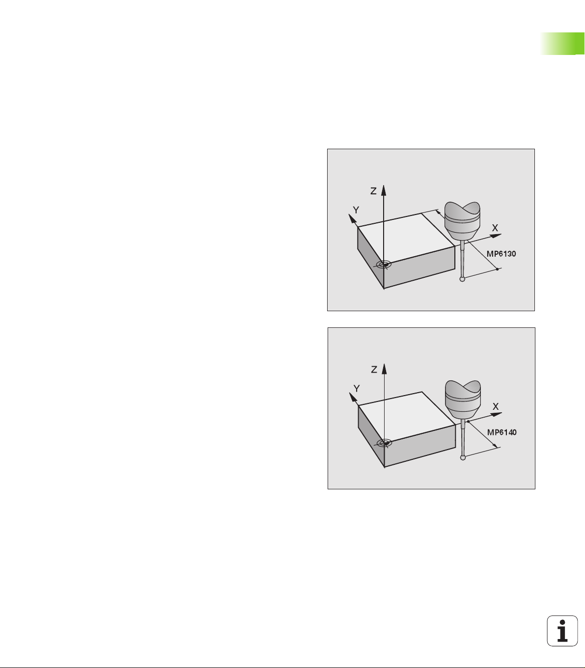
Maximum traverse to touch point: MP6130 ..... 17
Safety clearance to touch point: MP6140 ..... 17
Orient the infrared touch probe to the programmed probe direction: MP6165 ..... 17
Multiple measurement: MP6170 ..... 17
Confidence interval for multiple measurement: MP6171 ..... 17
Touch trigger probe, probing feed rate: MP6120 ..... 18
Touch trigger probe, rapid traverse for pre-positioning: MP6150 ..... 18
Running touch probe cycles ..... 19
Contents
HEIDENHAIN iTNC 530 9

2 Touch Probe Cycles in the Manual and Electronic Handwheel Modes ..... 21
2.1 Introduction ..... 22
Overview ..... 22
Selecting probe cycles ..... 22
Contents
Recording measured values from the touch probe cycles ..... 23
Writing the measured values from touch probe cycles in datum tables ..... 24
Writing the measured values from touch probe cycles in the preset table ..... 25
2.2 Calibrating a Touch Trigger Probe ..... 26
Introduction ..... 26
Calibrating the effective length ..... 26
Calibrating the effective radius and compensating center misalignment ..... 27
Displaying calibration values ..... 28
Managing more than one block of calibrating data ..... 29
2.3 Compensating Workpiece Misalignment ..... 30
Introduction ..... 30
Measuring the basic rotation ..... 30
Saving the basic rotation in the preset table ..... 31
Displaying a basic rotation ..... 31
Cancel a basic rotation ..... 31
2.4 Setting the Datum with a 3-D Touch Probe ..... 32
Introduction ..... 32
To set the datum in any axis (see figure at right) ..... 32
Corner as datum—using points that were already probed for a basic rotation (see figure at right) ..... 33
Corner as datum—without using points that were already probed for a basic rotation ..... 33
Circle center as datum ..... 34
Center line as datum ..... 35
Setting datum points using holes/cylindrical studs ..... 36
2.5 Measuring Workpieces with a 3-D Touch Probe ..... 37
Introduction ..... 37
To find the coordinate of a position on an aligned workpiece: ..... 37
Finding the coordinates of a corner in the working plane ..... 37
Measuring workpiece dimensions ..... 38
To find the angle between the angle reference axis and a side of the workpiece ..... 39
2.6 Using the Touch Probe Functions with Mechanical Probes or Dial Gauges ..... 40
Introduction ..... 40
10 Contents

3 Touch Probe Cycles for Automatic Workpiece Inspection ..... 41
3.1 Measuring Workpiece Misalignment ..... 42
Overview ..... 42
Characteristics common to all touch probe cycles for measuring workpiece misalignment ..... 42
BASIC ROTATION (touch probe cycle 400,
ISO: G400) ..... 43
BASIC ROTATION from two holes (touch probe cycle 401, ISO: G401) ..... 45
BASIC ROTATION over two studs (touch probe cycle 402, ISO: G402) ..... 47
BASIC ROTATION compensation via rotary axis (touch probe cycle 403, ISO: G403) ..... 50
BASIC ROTATION (touch probe cycle 404, ISO: G404) ..... 53
Compensating workpiece misalignment by rotating the C axis (touch probe cycle 405, ISO: G405) ..... 54
3.2 Automatic Datum Determination ..... 58
Overview ..... 58
Characteristics common to all touch probe cycles for datum setting ..... 59
DATUM FROM INSIDE OF RECTANGLE (touch probe cycle 410, ISO: G410) ..... 61
DATUM FROM OUTSIDE OF RECTANGLE (touch probe cycle 411, ISO: G411) ..... 64
DATUM FROM INSIDE OF CIRCLE (touch probe cycle 412, ISO: G412) ..... 67
DATUM FROM OUTSIDE OF CIRCLE (touch probe cycle 413, ISO: G413) ..... 70
DATUM FROM OUTSIDE OF CORNER (touch probe cycle 414, ISO: G414) ..... 73
DATUM FROM INSIDE OF CORNER (touch probe cycle 415, ISO: G415) ..... 76
DATUM CIRCLE CENTER (touch probe cycle 416, ISO: G416) ..... 79
DATUM IN TOUCH PROBE AXIS (touch probe cycle 417, ISO: G417) ..... 82
DATUM AT CENTER BETWEEN 4 HOLES (touch probe cycle 418, ISO: G418) ..... 84
DATUM IN ONE AXIS (touch probe cycle 419, ISO: G419) ..... 87
Contents
HEIDENHAIN iTNC 530 11

Contents
3.3 Automatic Workpiece Measurement ..... 93
Overview ..... 93
Recording the results of measurement ..... 94
Measurement results in Q parameters ..... 95
Classification of results ..... 95
Tolerance monitoring ..... 95
Tool monitoring ..... 96
Reference system for measurement results ..... 96
REFERENCE PLANE (touch probe cycle 0, ISO: G55) ..... 97
DATUM PLANE (touch probe cycle 1) ..... 98
MEASURE ANGLE (touch probe cycle 420, ISO: G420) ..... 99
MEASURE HOLE (touch probe cycle 421, ISO: G421) ..... 101
MEASURE CIRCLE OUTSIDE (touch probe cycle 422, ISO: G422) ..... 104
MEASURE RECTANGLE FROM INSIDE (touch probe cycle 423, ISO: G423) ..... 107
MEASURE RECTANGLE FROM OUTSIDE (touch probe cycle 424, ISO: G424) ..... 110
MEASURE INSIDE WIDTH (touch probe cycle 425, ISO: G425) ..... 113
MEASURE RIDGE WIDTH (touch probe cycle 426, ISO: G426) ..... 115
MEASURE COORDINATE (touch probe cycle 427, ISO: G427) ..... 117
MEASURE BOLT HOLE CIRCLE (touch probe cycle 430, ISO: G430) ..... 119
MEASURE PLANE (touch probe cycle 431, ISO: G431) ..... 122
3.4 Special Cycles ..... 128
Overview ..... 128
CALIBRATE TS (touch probe cycle 2) ..... 129
CALIBRATE TS LENGTH (touch probe cycle 9) ..... 130
MEASURING (touch probe cycle 3) ..... 131
MEASURE AXIS OFFSET (touch probe cycle 440, ISO: G440) ..... 132
4 Touch Probe Cycles for Automatic Tool Measurement ..... 135
4.1 Tool Measurement with the TT Tool Touch Probe ..... 136
Overview ..... 136
Setting the machine parameters ..... 136
Entries in the tool table TOOL.T ..... 138
Display the results of measurement ..... 139
4.2 Available Cycles ..... 140
Overview ..... 140
Differences between Cycles 31 to 33 and Cycles 481 to 483 ..... 140
Calibrating the TT (touch probe cycle 30 or 480, ISO: G480) ..... 141
Measuring the tool length (touch probe cycle 31 or 481, ISO: G481) ..... 142
Measuring the tool radius (touch probe cycle 32 or 482, ISO: G482) ..... 144
Measuring the tool radius (touch probe cycle 33 or 483, ISO: G483) ..... 146
12 Contents

Introduction
1.1 General Information on Touch
Probe Cycles
The TNC must be specially prepared by the machine tool
builder for the use of a 3-D touch probe.
If you are carrying out measurements during program run,
be sure that the tool data (length, radius) can be used from
the calibrated data or from the last TOOL CALL block
(selected with MP7411).
Function
Whenever the TNC runs a touch probe cycle, the 3-D touch probe
approaches the workpiece in one linear axis. This is also true during an
active basic rotation or with a tilted working plane. The machine tool
builder determines the probing feed rate in a machine parameter (see
“Before You Start Working with Touch Probe Cycles” later in this
chapter).
When the probe stylus contacts the workpiece,
the 3-D touch probe transmits a signal to the TNC: the coordinates
of the probed position are stored,
the touch probe stops moving, and
returns to its starting position at rapid traverse.
If the stylus is not deflected within a distance defined in MP 6130, the
TNC displays an error message.
Z
Y
F
F MAX
X
1.1 General Information on Touch Probe Cycles
14 1 Introduction
Touch probe cycles in the Manual and Electronic Handwheel modes
In the Manual and Electronic Handwheel operating modes, the TNC
provides touch probe cycles that allow you to:
Calibrate the touch probe
Compensate workpiece misalignment
Datum setting
Touch probe cycles for automatic operation
Besides the touch probe cycles, which you can use in the Manual and
Electronic handwheel operating modes, several cycles are available
for a wide variety of applications in automatic operation:
Calibrating the touch probe (Chapter 3)
Compensating workpiece misalignment (Chapter 3)
Setting datums (Chapter 3)
Automatic workpiece inspection (Chapter 3)
Automatic workpiece measurement (Chapter 4)
You can program the touch probe cycles in the Programming and
Editing operating mode via the TOUCH PROBE key. Like the most
recent fixed cycles, touch probe cycles use Q parameters with
numbers of 400 and above as transfer parameters. Parameters with
specific functions that are required in several cycles always have the
same number: For example, Q260 is always assigned the clearance
height, Q261 the measuring height, etc.
To simplify programming, the TNC shows an illustration during cycle
definition. In the illustration, the parameter that needs to be entered is
highlighted (see figure at right).
1.1 General Information on Touch Probe Cycles
HEIDENHAIN iTNC 530 15
Defining the touch probe cycle in the Programming and Editing
operation mode
8 The soft-key row shows all available touch probe
functions divided into groups.
8 Select the desired probe cycle, for example datum
setting. Digitizing cycles and cycles for automatic tool
measurement are available only if your machine has
been prepared for them.
8 Select a cycle, e.g. datum setting at pocket. The TNC
initiates the programming dialog and asks all required
input values. At the same time a graphic of the input
parameters is displayed in the right screen window.
The parameter that is asked for in the dialog prompt
is highlighted.
8 Enter all parameters requested by the TNC and
conclude each entry with the ENT key.
8 The TNC ends the dialog when all required data has
been entered.
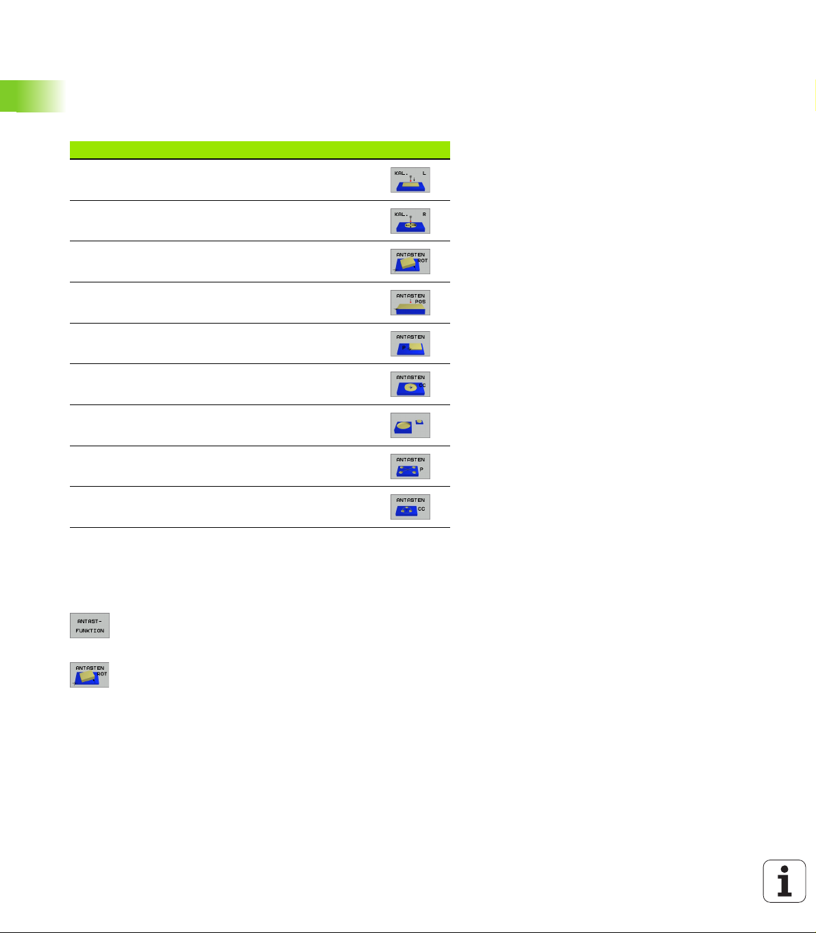
Group of measuring cycles Soft key
Cycles for automatic measurement and compensation
of workpiece misalignment
Cycles for automatic datum setting
Example: NC blocks
5 TCH PROBE 410 DATUM INSIDE RECTAN.
Q321=+50 ;CENTER IN 1ST AXIS
Q322=+50 ;CENTER IN 2ND AXIS
Q323=60 ;1ST SIDE LENGTH
Q324=20 ;2ND SIDE LENGTH
Q261=-5 ;MEASURING HEIGHT
Q320=0 ;SET-UP CLEARANCE
Q260=+20 ;CLEARANCE HEIGHT
Q301=0 ;TRAVERSE TO CLEARANCE HEIGHT
Q305=10 ;NO. IN TABLE
Q331=+0 ;DATUM
Q332=+0 ;DATUM
Q303=+1 ;MEAS. VALUE TRANSFER
Cycles for automatic workpiece inspection
Automatic calibration cycle
1.1 General Information on Touch Probe Cycles
Cycles for automatic tool measurement (enabled by
the machine tool builder)
16 1 Introduction
1.2 Before You Start Working with
Touch Probe Cycles!
To make it possible to cover the widest possible range of applications,
machine parameters enable you to determine the behavior common
to all touch probe cycles:
Maximum traverse to touch point: MP6130
If the stylus is not deflected within the path defined in MP6130, the
TNC outputs an error message.
Safety clearance to touch point: MP6140
In MP6140 you define how far from the defined (or calculated) touch
point the TNC is to pre-position the touch probe. The smaller the value
you enter, the more exactly must you define the touch point position.
In many touch probe cycles you can also define a setup clearance in
addition that is added to Machine Parameter 6140.
Orient the infrared touch probe to the programmed probe direction: MP6165
To increase measuring accuracy, you can use MP 6165 = 1 to have an
infrared touch probe oriented in the programmed probe direction
before every probe process. In this way the stylus is always deflected
in the same direction.
Multiple measurement: MP6170
To increase measuring certainty, the TNC can run each probing
process up to three times in sequence. If the measured position
values differ too greatly, the TNC outputs an error message (the limit
value is defined in MP6171). With multiple measurement it is possible
to detect random errors, e.g., from contamination.
If the measured values lie within the confidence interval, the TNC
saves the mean value of the measured positions.
Confidence interval for multiple measurement: MP6171
In MP6171 you store the value by which the results may differ when
you make multiple measurements. If the difference in the measured
values exceeds the value in MP6171, the TNC outputs an error
message.
HEIDENHAIN iTNC 530 17
1.2 Before You Start Working with Touch Probe Cycles!

Touch trigger probe, probing feed rate: MP6120
In MP6120 you define the feed rate at which the TNC is to probe the
workpiece.
Touch trigger probe, rapid traverse for prepositioning: MP6150
In MP6150 you define the feed rate at which the TNC pre-positions the
touch probe, or positions it between measuring points.
1.2 Before You Start Working with Touch Probe Cycles!
18 1 Introduction
Running touch probe cycles
All touch probe cycles are DEF active. This means that the TNC runs
the cycle automatically as soon as the TNC executes the cycle
definition in the program run.
Make sure that at the beginning of the cycle the
compensation data (length, radius) from the calibrated
data or from the last TOOL CALL block are active
(selection via MP7411, see the User's Manual of the
iTNC 530, “General User Parameters”).
You can also run the touch probe cycles 410 to 419 during
an active basic rotation. Make sure, however, that the
basic rotation angle does not change when you use Cycle
7 DATUM SHIFT with datum tables after the measuring
cycle.
Touch probe cycles with a number greater than 400 position the touch
probe according to a positioning logic:
If the current coordinate of the south pole of the stylus is less than
the coordinate of the clearance height (defined in the cycle), the TNC
retracts the touch probe in the probe axis to the clearance height
and then positions it in the working plane to the first starting
position.
If the current coordinate of the south pole of the stylus is greater
than the coordinate of the clearance height, the TNC first positions
the probe in the working plane to the first starting position and then
moves it immediately to the measuring height in the touch probe
axis.
HEIDENHAIN iTNC 530 19
1.2 Before You Start Working with Touch Probe Cycles!

Touch Probe Cycles in the Manual and Electronic Handwheel Modes
2.1 Introduction
Overview
The following touch probe cycles are available in the Manual mode:
Function Soft key
Calibrate the effective length
2.1 Introduction
Calibrate the effective radius
Measure a basic rotation using a line
Datum setting in any axis
Set the datum at a corner
Set the datum at a circle center
Measure a basic rotation using two holes/cylindrical
studs
Set the datum using four holes/cylindrical studs
Set the circle center using three holes/cylindrical studs
Selecting probe cycles
8 Select the Manual Operation or Electronic Handwheel mode of
operation.
8 To choose the touch probe functions, press the
TOUCH PROBE soft key. The TNC displays additional
soft keys—see table above.
8 To select the probe cycle, press the appropriate soft
key, for example PROBING ROT, and the TNC
displays the associated menu.
22 2 Touch Probe Cycles in the Manual and Electronic Handwheel Modes
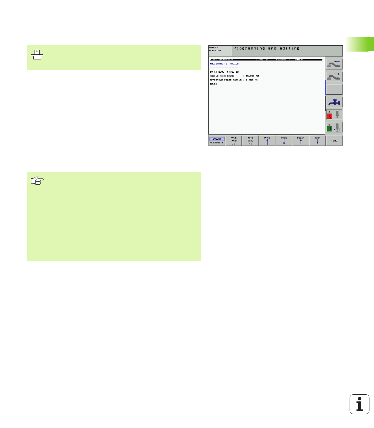
Recording measured values from the touch probe cycles
The TNC must be specially prepared by the machine tool
builder for use of this function. The machine tool manual
provides further information.
After executing any selected touch probe cycle, the TNC displays the
PRINT soft key. If you press this soft key, the TNC will record the
current values determined in the active touch probe cycle. You can
then use the PRINT function in the menu for setting the data interface
(see the User's Manual Chapter 12, “MOD Functions, Setting the
Data Interfaces”) to define whether the TNC is to
print the measuring result,
store the measuring results on the TNC’s hard disk, or
store the measuring results on a PC.
If you store the measuring results, the TNC creates the ASCII file
%TCHPRNT.A. Unless you define a specific path and interface in the
interface configuration menu, the TNC will store the %TCHPRNT file
in the main directory TNC:\.
When you press the PRINT soft key, the %TCHPRNT.A
file must not be
active in the Programming and Editing mode of operation.
The TNC will otherwise display an error message.
The TNC stores the measured data in the %TCHPRNT.A
file only. If you execute several touch probe cycles in
succession and want to store the resulting measured data,
you must make a backup of the contents stored in
%TCHPRNT.A between the individual cycles by copying
or renaming the file.
Format and contents of the %TCHPRNT file are preset by
the machine tool builder.
2.1 Introduction
HEIDENHAIN iTNC 530 23
Writing the measured values from touch probe cycles in datum tables
This function is active only if you have datum tables active
on your TNC (bit 3 in machine parameter 7224.0 =0).
Use this function if you want to save measured values in
the workpiece coordinate system. If you want to save
measured values in the machine-based coordinate system
(REF coordinates), press the ENTER IN PRESET TABLE
2.1 Introduction
With the ENTER IN DATUM TABLE soft key, the TNC can write the
values measured during a touch probe cycle in a datum table:
8 Select any probe function.
8 Enter the desired coordinates of the datum in the appropriate input
fields (depends on the touch probe cycle being run).
8 Enter the datum number in the Number in table= input box.
8 Enter the name of the datum table (complete path) in the Datum
table input box.
8 Press the ENTER IN DATUM TABLE soft key. The TNC saves the
datum in the indicated datum table under the entered number.
soft key (see “Writing the measured values from touch
probe cycles in the preset table” on page 25).
Note that during an active datum shift the TNC always
bases the probed value on the active preset (or on the
datum most recently set in the Manual operating mode),
although the datum shift is included in the position display.
24 2 Touch Probe Cycles in the Manual and Electronic Handwheel Modes
Writing the measured values from touch probe cycles in the preset table
Use this function if you want to save measured values in
the machine-based coordinate system (REF coordinates).
If you want to save measured values in the workpiece
coordinate system, press the ENTER IN DATUM TABLE
soft key (see “Writing the measured values from touch
probe cycles in datum tables” on page 24).
With the ENTER IN PRESET TABLE soft key, the TNC can write the
values measured during a probe cycle in the preset table. The
measured values are then stored referenced to the machine-based
coordinate system (REF coordinates). The preset table has the name
PRESET.PR, and is saved in the directory TNC:\.
Note that during an active datum shift the TNC always
bases the probed value on the active preset (or on the
datum most recently set in the Manual operating mode),
although the datum shift is included in the position display.
8 Select any probe function.
8 Enter the desired coordinates of the datum in the appropriate input
fields (depends on the touch probe cycle being run).
8 Enter the preset number in the Number in table: input box.
8 Press the ENTER IN PRESET TABLE soft key. The TNC saves the
datum in the preset table under the entered number.
2.1 Introduction
HEIDENHAIN iTNC 530 25
2.2 Calibrating a Touch Trigger
Probe
Introduction
The touch probe must be calibrated in the following cases:
Commissioning
Stylus breakage
Stylus exchange
Change in the probe feed rate
Irregularities caused, for example, when the machine heats up
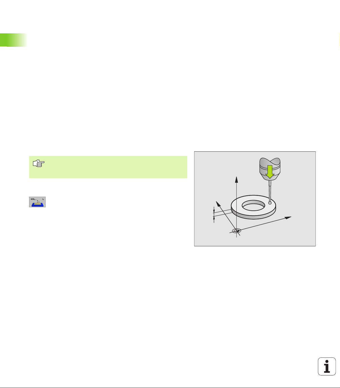
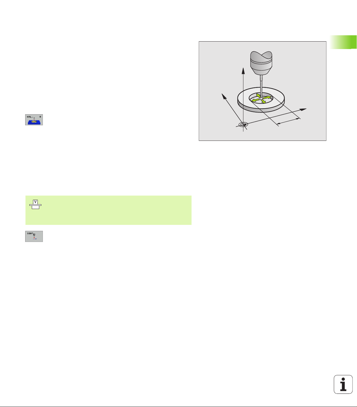
During calibration, the TNC finds the “effective” length of the stylus
and the “effective” radius of the ball tip. To calibrate the touch probe,
clamp a ring gauge of known height and known internal radius to the
machine table.
Calibrating the effective length
The effective length of the touch probe is always
referenced to the tool datum. The machine tool builder
2.2 Calibrating a Touch Trigger Probe
8 Set the datum in the spindle axis such that for the machine tool table
Z=0.
usually defines the spindle tip as the tool datum.
8 To select the calibration function for the touch probe
length, press the TOUCH PROBE and CAL. L soft
keys. The TNC then displays a menu window with
four input fields.
8 Enter the tool axis (with the axis key).
8 Datum: Enter the height of the ring gauge.
8 The menu items Effective ball radius and Effective
length do not require input.
8 Move the touch probe to a position just above the ring
gauge.
8 To change the traverse direction (if necessary) press a
soft key or an arrow key.
8 To probe the upper surface of the ring gauge, press
the machine START button.
Z
Y
5
X
26 2 Touch Probe Cycles in the Manual and Electronic Handwheel Modes
Calibrating the effective radius and compensating center misalignment
After the touch probe is inserted, it normally needs to be aligned
exactly with the spindle axis. The misalignment is measured with this
calibration function and compensated electronically.
For this operation the TNC rotates the 3-D touch probe by 180°. The
rotation is initiated by a miscellaneous function that is set by the
machine tool builder in machine parameter 6160.
The center misalignment is measured after the effective ball tip radius
is calibrated.
8 In the Manual Operation mode, position the ball tip in the bore of the
ring gauge.
8 To select the calibration function for the ball-tip radius
and the touch probe center misalignment, press the
CAL. R soft key.
8 Select the tool axis and enter the radius of the ring
gauge.
8 To probe the workpiece, press the machine START
button four times. The touch probe contacts a
position on the bore in each axis direction and
calculates the effective ball-tip radius.
8 If you want to terminate the calibration function at this
point, press the END soft key.
Z
Y
X
10
2.2 Calibrating a Touch Trigger Probe
In order to be able to determine ball-tip center
misalignment, the TNC needs to be specially prepared by
the machine manufacturer. The machine tool manual
provides further information.
8 If you want to determine the ball-tip center
misalignment, press the180° soft key. The TNC
rotates the touch probe by 180°.
8 To probe the workpiece, press the machine START
button four times. The touch probe contacts a
position on the bore in each axis direction and
calculates the ball-tip center misalignment.
HEIDENHAIN iTNC 530 27
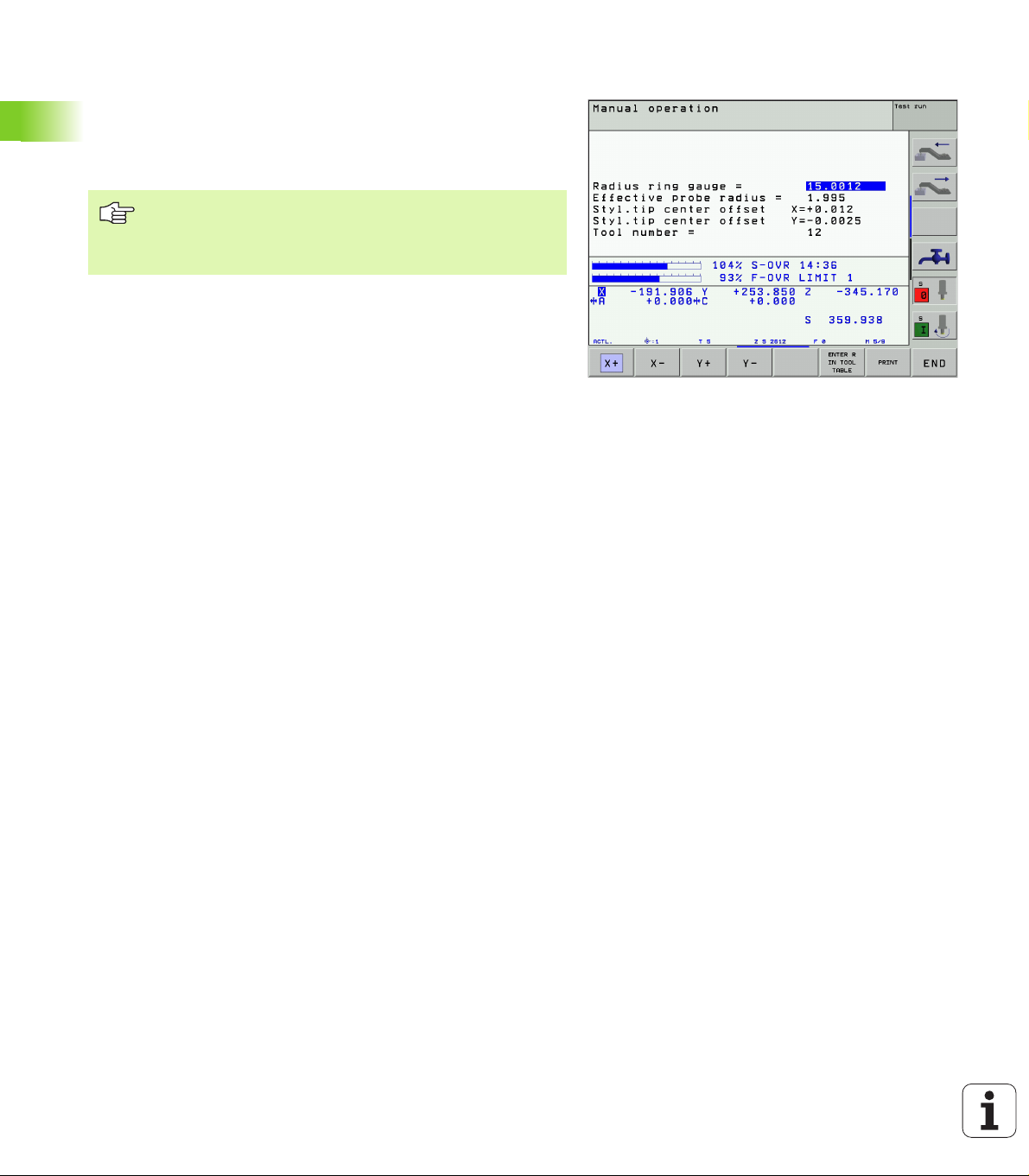
Displaying calibration values
The TNC stores the effective length and radius, as well as the center
misalignment, for use when the touch probe is needed again. You can
display the values on the screen with the soft keys CAL. L and CAL. R.
Storing calibration values in the TOOL.T tool table
This function is only available if bit 0 in Machine Parameter
7411 = 1 is set (activate touch probe data with TOOL CALL),
and tool table TOOL.T is active (Machine Parameter 7260
not equal to 0).
If you conduct measurements during program run, the compensation
data for the touch probe can be activated from the tool table via a TOOL
CALL. To store the calibration data in the TOOL.T tool table, enter the
tool number in the calibration menu (confirm with ENT) and then press
the ENTER R IN TOOL TABLE or the ENTER L IN TOOL TABLE soft
key.
2.2 Calibrating a Touch Trigger Probe
28 2 Touch Probe Cycles in the Manual and Electronic Handwheel Modes

Managing more than one block of calibrating data
If you use several touch probes or measuring contacts arranged in a
cross shape on your machine, you must also use several sets of
calibration data, if required.
To be able to use more than one block of calibration data, you must set
bit one in Machine Parameter 7411. Although the calibration data
(length, radius, center misalignment, and spindle angle) are calculated
in the calibration menu, you must always save them in the tool table
TOOL.T under a tool number that can be selected in the calibration
menu (see also User's Manual, section 5.2, “Tool Data”).
8 Execute the calibration function (as described previously).
8 Enter the tool number in the corresponding input box.
8 Enter the calculated calibration data in the tool table by pressing the
ENTER-R IN TOOL TABLE or ENTER L IN TOOL TABLE soft key.
If you use the touch probe afterwards, you must first
activate the corresponding tool number with a tool call
before executing a touch probe cycle, regardless of
whether you wish to run the touch probe cycle in
automatic mode or manual mode.
You can view and edit the calibration data in the calibration
menu, but you must make sure to write the changes back
into the tool table by pressing the ENTER R IN TOOL
TABLE or ENTER L IN TOOL TABLE soft key. The TNC
does not write the calibration values into the table
automatically!
2.2 Calibrating a Touch Trigger Probe
HEIDENHAIN iTNC 530 29
2.3 Compensating Workpiece
Misalignment
Introduction
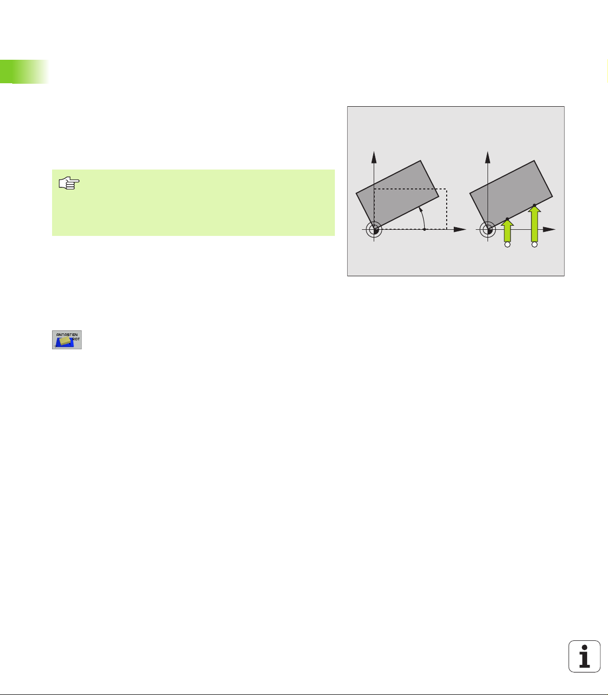
The TNC electronically compensates workpiece misalignment by
computing a “basic rotation.”
For this purpose, the TNC sets the rotation angle to the desired angle
with respect to the reference axis in the working plane. See figure at
right.
Select the probe direction perpendicular to the angle
reference axis when measuring workpiece misalignment.
To ensure that the basic rotation is calculated correctly
during program run, program both coordinates of the
working plane in the first positioning block.
Measuring the basic rotation
8 Select the probing function by pressing the PROBING
ROT soft key.
2.3 Compensating Workpiece Misalignment
8 Position the ball tip at a starting position near the first
touch point.
8 Select the probe direction perpendicular to the angle
reference axis: Select the axis by soft key.
8 To probe the workpiece, press the machine START
button.
8 Position the ball tip at a starting position near the
second touch point.
8 To probe the workpiece, press the machine START
button. The TNC determines the basic rotation and
displays the angle after the dialog Rotation angle =
Y
PA
Y
X
A B
X
30 2 Touch Probe Cycles in the Manual and Electronic Handwheel Modes
 Loading...