

Page 1

Gateway ALR
8200R
User’ s Guide
Part #8502953 A MAN US GW2K 8200R USR GDE R0 6/98
In our effort to use nature’s resources efficiently and wisely , w e print all manuals on recycled papers that meet the
minimum requirements established by the Federal EPA in its guidelines for recycled paper products.
Page 2

Notices
pyrig
)
g
g
g
g
g
g
g
g
Copyright © 1998 Gateway 2000, Inc.
All Rights Reserved
610 Gateway Drive
N. Sioux City, SD 57049 USA
All Rights Reserved
This publication is protected by copyright and all rights are reserved. No part of it may be reproduced
or transmitted by any means or in any form, without prior consent in writing from Gateway 2000.
The information in this manual has been carefully checked and is believed to be accurate. However,
changes are made periodically. These changes are incorporated in newer publication editions.
Gateway 2000 may improve and/or change products described in this publication at any time. Due to
continuing system improvements, Gateway 2000 is not responsible for inaccurate information which
may appear in this manual. For the latest product updates, consult the Gateway 2000 web site at
www.gatewa y.com. In no ev en t will Gatew a y 2000 be liab le for direct, indirect, special, exemplary,
incidental, or consequential damages resulting from any defect or omission in this manual, even if
advised of the possibility of such damages.
In the interest of continued product development, Gateway 2000 reserves the right to make
improvements in this manual and the products it describes at any time, without notices or obligation.
T r ademark Acknowledgments
AnyKey, black-and-white spot design, ColorBook, CrystalScan, Destination, EZ Pad, EZ Point, Field
Mouse, Gateway 2000, HandBook, Liberty, T eleP ath, Vivitron, stylized “G” design, and “Y ou’ve got a
friend in the business” slogan are registered trademarks and “All the big trends start in South Dakota”
slogan, GA TEW AY, and Gatewa y Solo are trademarks of Gateway 2000, Inc. Intel, Intel Inside logo,
and Pentium are registered trademarks and MMX is a trademark of Intel Corporation. Microsoft, MS,
MS-DOS, and Windows are trademarks or registered trademarks of Microsoft Corporation. All other
product names mentioned herein are used for identification purposes only, and may be the trademarks
or registered trademarks of their respective companies.
ii Gateway ALR 8200R User’s Guide
ht © 1998 Advanced Logic Research, Inc. (ALR
Co
All Rights Reserved
9401 Jeronimo
Irvine, CA 92618 USA
All Rights Reserved
This publi cati on is prot ecte d by co py right and all rights are reserved. No part of it may be reproduced
or transmitted by any means or in any form, without prior consent in writin
The information in this manual has been carefully checked and is believed to be accurate. However,
chan
es are made perio di call y. These cha nges are incorpo rat ed in ne we r publ ic atio n edit ion s. AL R
may improve and/or chan
system improvements, ALR is not responsible for inaccurate information which may appear in this
manual. For the latest product updates, consult the ALR web site at
be liable for direct, indirect, special, exemplary, incidental, or consequential dama
any defect or omission in this manual, even if advised of the possibility of such dama
In the interest of continued product development, ALR reserves the ri
manual and the products it describes at any time, without notices or obli
Trademark Acknowledgments
ALR is a registered trademark of Advanced Logic Research, Inc. All other product names mentioned
herein are used for identification purposes only, and may be the trademarks or re
of their respective companies.
e products des cri bed i n this publ ica tio n at an y time . Due t o con tinu ing
from ALR.
www.al r.com
ht to make improvements in this
. In no event will ALR
es resulting from
ation.
istered trademarks
es.
Page 3

Contents
Preface ................ .............. .............. .......... .............. .............. ..vii
About This Guide................................................................................ viii
Conventions Used in this Guide............................................................ ix
Getting Started ....................... ........................ .................. ........ 1
Before You Begin.................................................................................... 2
System Access......................................................................................... 3
Static Electricity Precautions........................................................... 3
Opening the System......................................................................... 3
Closing the System........................................................................... 5
Installing the Processor Drawer.............................................................. 7
Inspecting the Contents.................................................................... 7
Installing the Processor Drawer in the Rack................................... 8
Connecting Peripherals.................................................................. 13
Using an AutoSwitcher with Multiple System Drawers.............. 14
Powering Up the System....................................................................... 16
Quick Check................................................................................... 16
Completing the Installation............................................................ 18
System Features .......... ....................... ........................ ..........21
Basic Features........................................................................................ 22
Front Panel............................................................................................. 24
Dual Redundant 400-Watt Power Supplies.................................. 24
3.5-inch Diskette Drive.................................................................. 25
CD-ROM Drive.............................................................................. 25
LED Indicators............................................................................... 26
Buttons............................................................................................ 26
RAID Cage Bay ............................................................................. 26
Rear Panel.............................................................................................. 27
I/O Ports.......................................................................................... 27
Power Connectors.......................................................................... 28
Expansion Slot Cover Plates.......................................................... 28
System Board......................................................................................... 29
Chassis Fans ................................................................................... 30
Power Connectors.......................................................................... 30
Front Panel Connectors.................................................................. 31
iii
Page 4

Drive Controllers and Connectors................................................. 32
Server Management Connectors................................................... 33
System Jumpers............................................................................. 34
Battery............................................................................................ 35
Expansion Slots.............................................................................. 35
I/O Connectors............................................................................... 35
Processor Subsystem..................................................................... 36
Memory.......................................................................................... 37
Components ...........................................................................39
Processors.............................................................................................. 40
Installing a Pentium II Processor................................................... 41
Installing A VRM (for Processor 2).............................................. 44
Changing the Processor Speed...................................................... 45
System Memory.................................................................................... 46
Configuring Your Memory........................................................... 46
Installing DIMMs.......................................................................... 47
Adapter Cards ....................................................................................... 49
Storage Bays.......................................................................................... 51
Removing the Drive Bay Assembly............................................. 52
Removing the 5.25-inch Device.................................................... 53
Installing a 5.25-inch Device......................................................... 54
3.5-inch Devices............................................................................ 55
RAID Bay ...................................................................................... 58
BIOS Setup ................... ................... ....................... ................65
iv Gateway ALR 8200R User’s Guide
About the BIOS Setup Utility............................................................... 66
Using the BIOS Setup Utility............................................................... 67
Main Menu Screen......................................................................... 68
Advanced Menu Screen................................................................. 72
Security Menu Screen.................................................................... 81
Power Menu Screen....................................................................... 83
Boot Menu Screen......................................................................... 84
Exit Menu Screen........................................................................... 86
Updating the BIOS................................................................................ 87
Page 5

Maintaining and Cleaning Your System ............ ....................89
Maintaining Your System..................................................................... 90
Maintaining your Hard Drive ........................................................ 90
Cleaning The System............................................................................ 93
Cleaning the Mouse........................................................................ 93
Cleaning the Keyboard................................................................... 94
Cleaning the Monitor Screen......................................................... 94
Cleaning the Monitor Case............................................................ 94
Troubleshooting .....................................................................95
Introduction............................................................................................ 96
Important Safety Instructions................................................................ 97
Computer Virus Notice......................................................................... 99
What is a Virus............................................................................... 99
Types of Viruses............................................................................. 99
Virus Contamination...................................................................... 99
Protecting Your System............................................................... 100
Virus Prevention........................................................................... 100
Troubleshooting Checklist.................................................................. 102
Verifying Your Configuration..................................................... 102
Troubleshooting Guidelines......................................................... 102
CD-ROM Problems ............................................................................ 103
Hard Disk Problems............................................................................ 104
Memory/Processor Problems.............................................................. 105
Modem Problems................................................................................ 106
Peripheral/Adapter Problems.............................................................. 107
Printer Problems.................................................................................. 109
System Problems................................................................................. 110
Video Problems................................................................................... 112
Error Messages.................................................................................... 114
Setting the Jumpers ............... ........................ ......................119
System Board Jumpers........................................................................ 120
Clear CMOS Jumper.................................................................... 120
Processor Setting Jumper............................................................. 120
v
Page 6

RAID Backplane Jumpers.................................................................. 121
SCSI ID Address Settings ........................................................... 121
Active Termination...................................................................... 122
Auto Start/Delay Start.................................................................. 122
Cluster Option.............................................................................. 123
Regulatory Compliance Statements ....................................125
FCC Notice.......................................................................................... 126
Industry Canada Notice...................................................................... 127
CE Notice............................................................................................ 127
VCCI Notice ....................................................................................... 128
Australia/New Zealand Notice........................................................... 128
Index .....................................................................................129
vi Gateway ALR 8200R User’s Guide
Page 7

Pref ace
Contents
About This Guide .................................................viii
Conventions Used in this Guide.............................ix
Page 8

About This Guide
The purpose of this User’s Guide is to help you unpack, ass emble, and
install the system. This guide provides step-by-step setup and operating
instructions along with detailed illu strations throughout t he document.
Below is a summary of the sections to f ollo w:
Chapter 1: Get ting Started cov ers information about the int ernal and
external features as w ell as the syst em architecture and supported operat ing
systems.
Chapter 2: Sy stem F eat ures explains the main features of your system,
including ho w to assembl e it, identifying connec tors and arranging your
workspace.
Chapter 3: Components describes the major components inc luded in the
system.
Chapter 4: BIOS Setup describes the BIOS setup util ity and pro vides
detailed descriptions of the scre ens, fields, and options within that program.
Chapter 5: Maintai ning and Cleaning Y our Syst em pro vides instructions on
standard maintenance tasks and proced ures for cleanin g the exterior
portions of the computer .
Chapter 6: T r oubleshooti ng provides detail ed instructions on
troubleshooting v arious prob lems that you ma y e xperience whi le running
the server .
We recommend you take time to read through the man ual before using the
system. If you encounter a prob lem, refer to the h andy troublesho oting
section in this guide.
viii Gateway ALR 8200R User’s Guide
Page 9
Con ventions Used in this Guide
Setup
ARIAL NARROW
Throughout this booklet, you will see the fol lo wing con ventions :
Convention Description
E
NTER
C
+ ALT + D
TRL
EL
System User's Guide
Run
Sidebars Sidebars denote critical information
Note:
This is an example of an
important note that may
appear in the manual.
A key name corresponds to a key on
the keyboard.
A plus sign indicates that the keys on
either side of it must be pressed
simultaneously.
Commands to be entered as well as
messages that appear on your
monitor are printed in “
font.
Names of publications and files are
italicized.
Options to select are boldfaced.
such as warnings, important
information, and important notes.
”
Conventions Used in this Guide ix
Page 10

x Gateway ALR 8200R User’s Guide
Page 11

Chapter 1:
Getting Started
Contents
Before You Begin.................................................... 2
System Access......................................................... 3
Static Electricity Precautions........................... 3
Opening the System ......................................... 3
Closing the System........................................... 5
Installing the Processor Drawer.............................. 7
Inspecting the Contents.................................... 7
Installing the Processor Drawer in the Rack ... 8
Connecting Peripherals.................................. 13
Powering Up the System....................................... 16
Quick Check................................................... 16
Completing the Installation............................ 18
Page 12

Before You Begin
Congratulations on your purchase. With the arriv al of your ne w system, you
are probabl y eager to install the processor dra w er in y our rack syste m and
have i t operating. This section sho ws y ou ho w to:
•
Access the system interior
•
Install the processor dra w er
•
Connect the monitor and keybo ard
•
Po w er up the syst em
Carefully read and f ollo w these instructions to e nsure that the system
operates correctly.
2 Gateway ALR 8200R User’s Guide
Page 13

System Access
Static Electricity Precautions
Caution! Prevent Static-Electricity Damage
Static Electricity Preventions
1.
WEAR A GROUNDING WRIST STRAP (a vailab le at most electronic stores).
2.
T urn off the system power.
3.
Touch the back of the power supply fan, located on the back of the case.
4.
UNPLUG ALL CORDS FR O M WALL OUTLET.
5.
Remove the system case cover .
Static Electricity Precautions
♦
A v oid static-causing surfaces such as plastic and styrofoam in your work area.
♦
Remove the parts from their antistatic bags only when you are ready to use them. Do not la y
parts on the outside of antistatic bags since only the inside provides antistatic protection.
♦
Alwa ys hold cards by their ed ges and their metal mounting bracket. Avoid touching
components on the cards and the edge connectors that connect to expansion slots.
♦
Never slide cards or other parts over any surface.
Opening the System
Depending on your purpose, you may need to open onl y the front portion of
the system, or you ma y need to remo v e the top co v er entirel y. Follo w the
instructions specific to the task you want to accomplish as indicated in each
section.
Removi ng the Top Cover
You can either open or remo v e the top co v er , depending on which i nternal
components you need to access. Opening the top co ver pr o vides access to
the pow er supp ly subsyst em, the blo w ers , the hard disk dri ve mount ing
brackets, the 3.5-inch disket te driv e, the data cab les and the RAID ba y
Caution!
Pow er the system OFF and
disconnect both power
cords before proceeding.
Installing any component
while the power is ON may
cause permanent damage
to the system.
This product contains
hazardous moving parts.
Ensure that
turned OFF and the power
cord(s) disconnected
before opening or removing
the cover .
the computer is
System Access 3
Page 14
Warning!
This product contains
hazardous moving parts.
Ensure that the computer is
turned OFF before opening
or removing the cover .
backplane. If you requir e access to the sy stem board to upgrade the
processor , install memory , or an adapter card, you must remove the top
cov er entirel y.
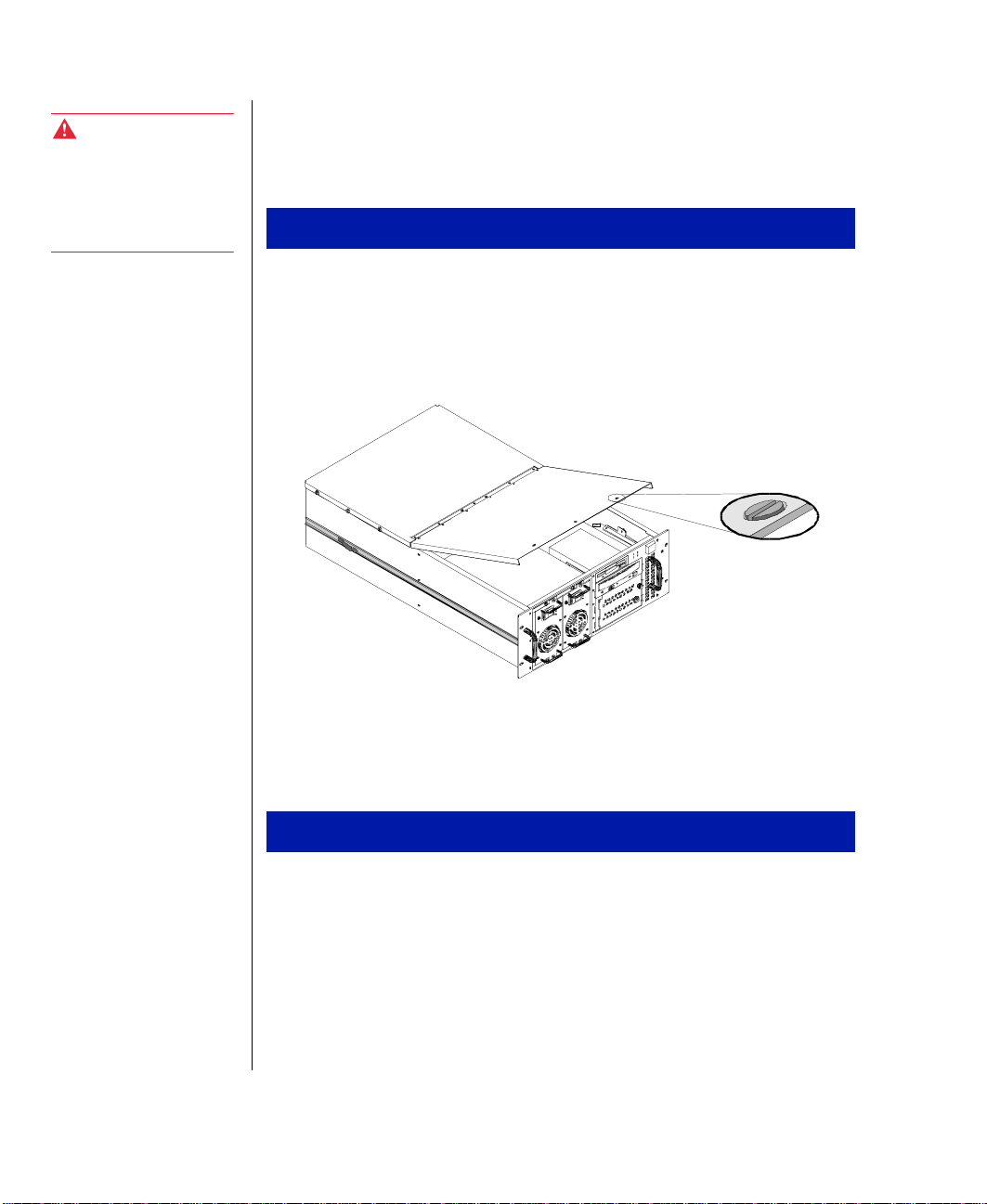
Opening the T op Cover
Disconnect both po wer cords and po w er do wn the system.
1.
On the top front of the system, turn each of the thr ee slotted retaine rs
2.
90 degrees counter-clockwise.
3.
1.
2.
4 Gateway ALR 8200R User’s Guide
Figur e 1: Openi ng the Top Cover
Lift the lid co verin g the front portion of the system.
Removing the T op Cover
Disconnect both po wer cords and po w er do wn the system.
On the top front of the system, turn each of the thr ee slotted retaine rs
90 degrees counter-clockwise.
Page 15
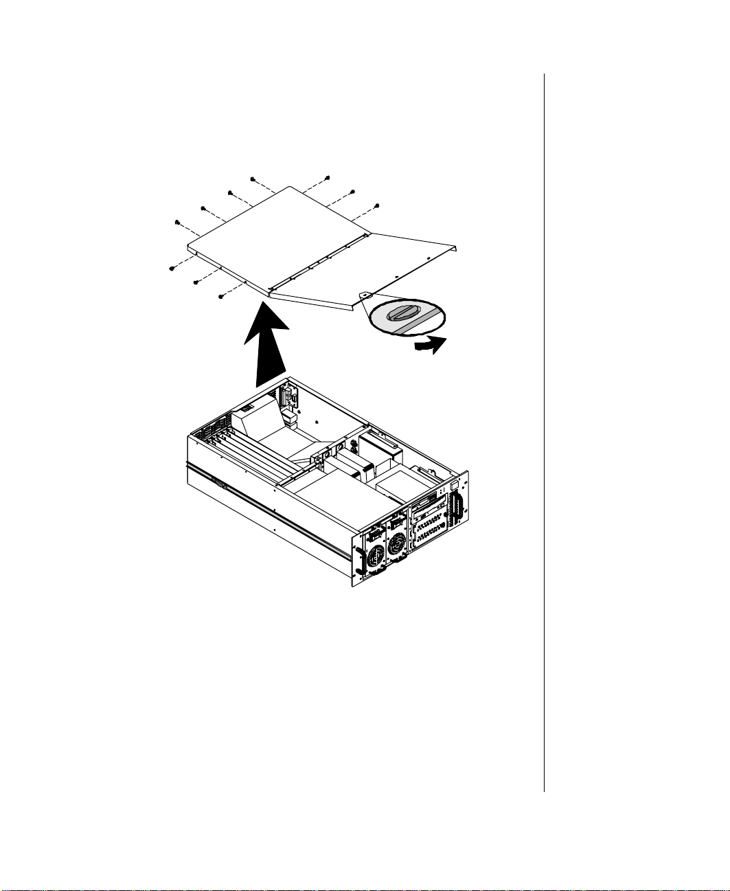
Remove the three scre ws from each side of the top co ver and the four
3.
screws from the back of t he top co ve r .
Remove the top co ver.
4.
Figur e 2: Remo ving the Top Cover
Closing the System
Before closing the system, ver ify that all connect ors and boards are
properly instal led and firmly seated.
System Access 5
Page 16
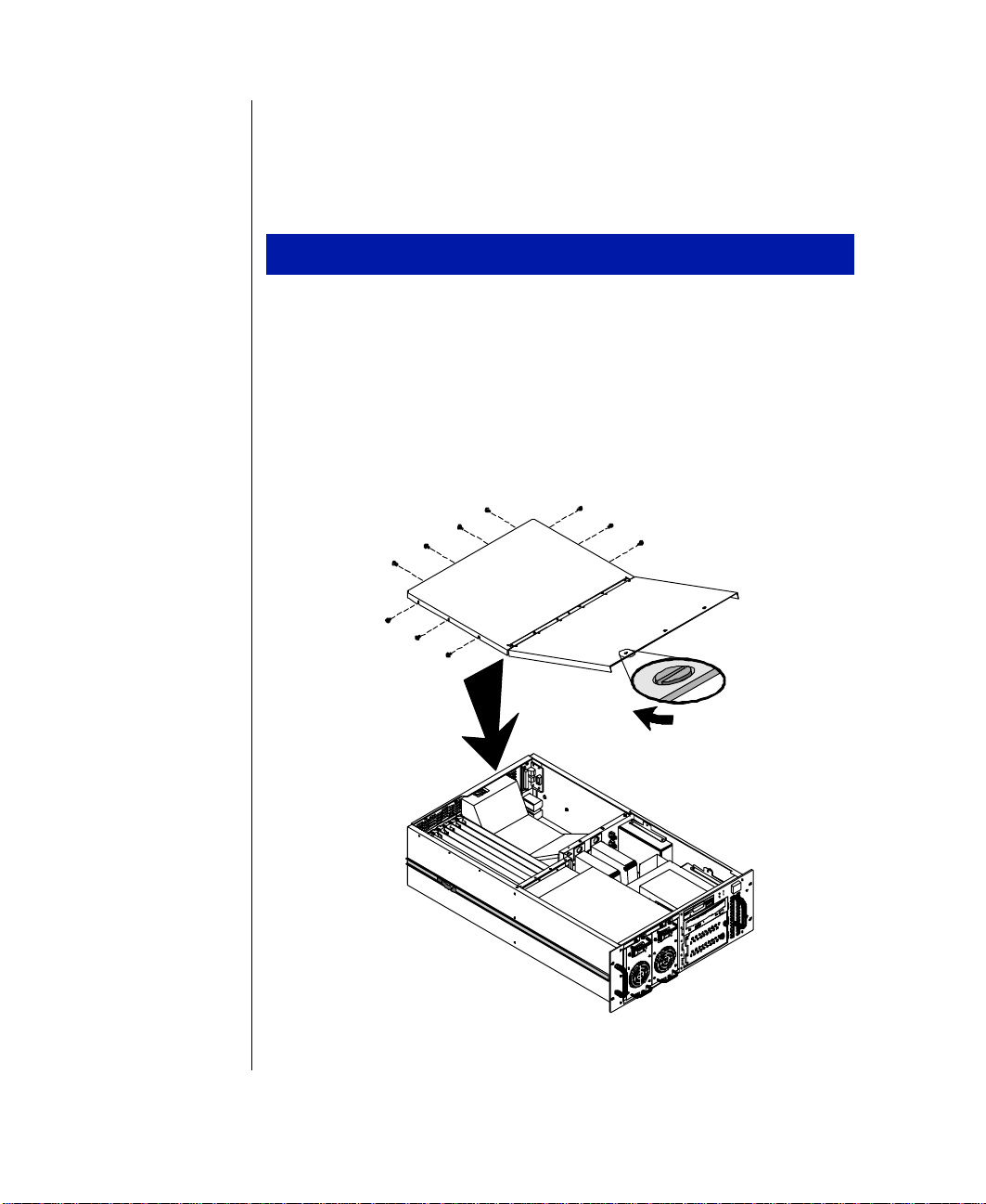
Reinstalling the T op Co ver
This procedure assumes that yo u have remov ed the top co ver entirel y. If you
opened the top co ver , but di d not remo ve it , close the co v er and refer to
Step 3 onl y .
Replacing the T op C over
Position t he top co ve r on the chassis, aligni ng the three holes on each
1.
side and four holes in back.
Reinstall the scre ws remo ved w hen the top cover was remov ed (three
2.
on each side and four in back).
T urn the three slott ed retainers 90 degrees clockwise to secure t he
3.
front portion of the top co ver in p lace.
6 Gateway ALR 8200R User’s Guide
Figur e 3: Rei nstalling the Top Cover
Page 17

Installing the Pr ocessor Drawer
1.
This processor dra w er is a 4U system, meaning that i t requires 7
vertical inches (1.75” x 4) of rack s pace for installat ion. Check the
rack configuration to make sure you ha ve at least this much space. You
may ha ve to remo v e blank p anels or rearrange existing dra w ers to
provide enough clearan ce.
2.
Protect the system from extreme temper ature and humidity. Position
the rack a wa y from direct sunl ight, heater ducts, and other hea tgenerating objects.
3.
Keep your sys tem a wa y fr om equipment that generates magnet ic
fields. Even a telephone placed too close to the system ma y cause
interference.
4.
If the new system dra w er is configured for A C operation, protect it
against A C line spikes b y using a 3-prong, 115-V or 230-V
(depending on the voltage supplied in yo ur locality), an d an AC surge
control outlet station. The sys tem ma y require tw o separa te A C outlets
(one per pow er suppl y).
Inspecting th e Contents
Unpack the carton and inspect the contents. Standar d systems include th e
following items:
•
System Draw er
•
Po w er Cab le(s)
•
User’s Guide
•
Utilities
•
Enhanced Keyboard
•
Mouse
Check the packing list to ensure t hat all equipment and associ ated manuals
are included in your sh ipment. Inspect e verything carefull y. If you suspect
any damage from shipping, contact Technical Support immediately
.
Important!
Keep the product carton
and foam packing, in case
you have to ship t he
system.
If you return the system in
different packaging, your
warranty may be voided.
Installing the Processor Drawer 7
Page 18
Installing the Processor Drawer in the Rac k
Rails must be installed on the proce ssor dra w er and in the cabi net before
you can install the pr ocessor dra w er .
Installing the Mounting Rails
Note:
Drawer heights are
measured in “U’s.” Each U
is 1.75 inches, measured
vertically on the rack. Your
processor drawer is a 4U
drawer , and is 7 inches
high.
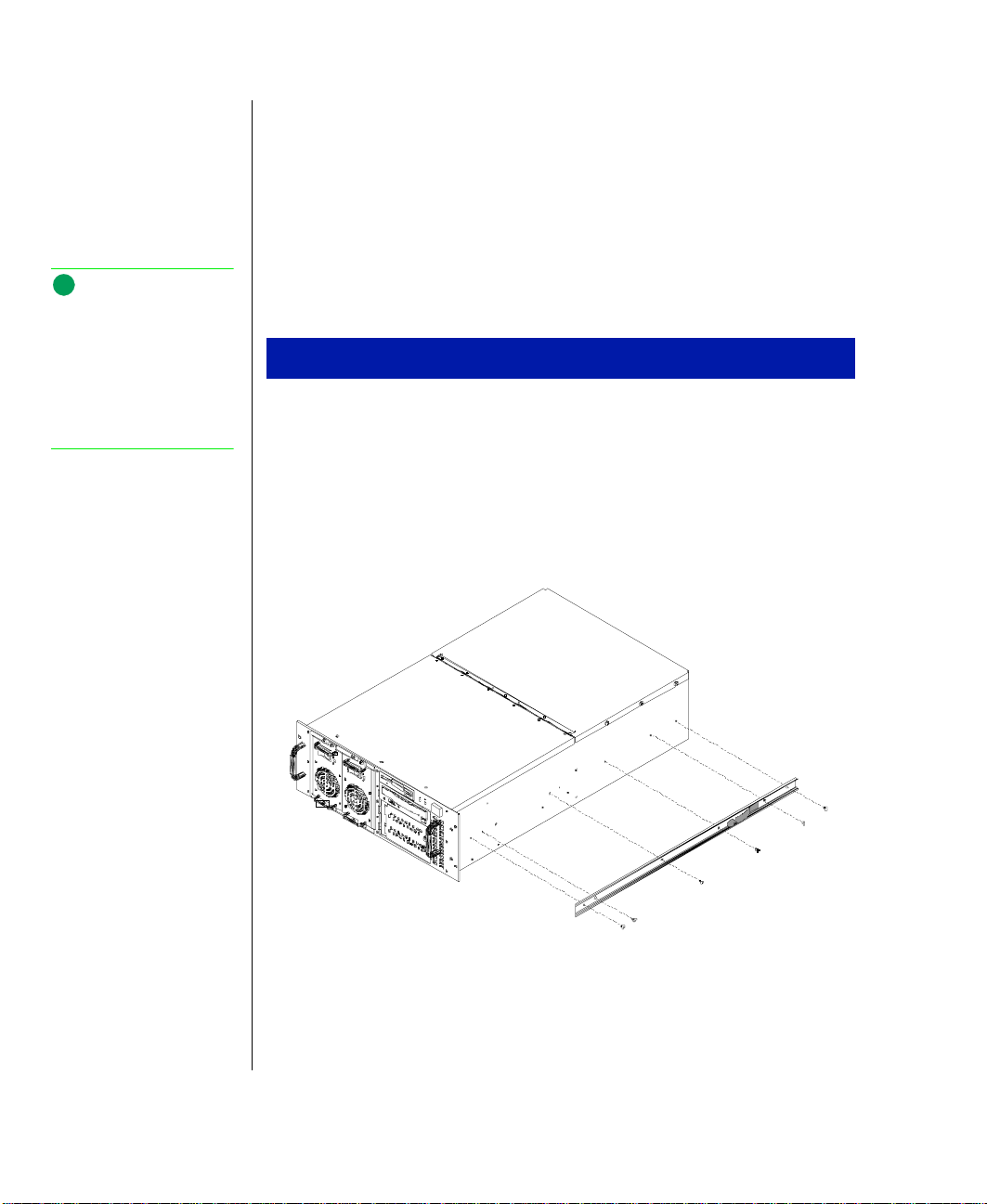
Install the mounting rails on t he processor dra w er.
Installing the Mounting Rails
After unpacking the processor dra w er , re mo ve the side rails from the
1.
mounting rails by depr essing the retention c lips and sliding them of f.
Mount the side rails on the processor dra w er with the tw elv e (12)
2.
screws pro vided. The ret ention clips sho uld go to ward the rear of the
cabinet.
8 Gateway ALR 8200R User’s Guide
Figur e 4: I nstalling the Mounting Rail s
Page 19

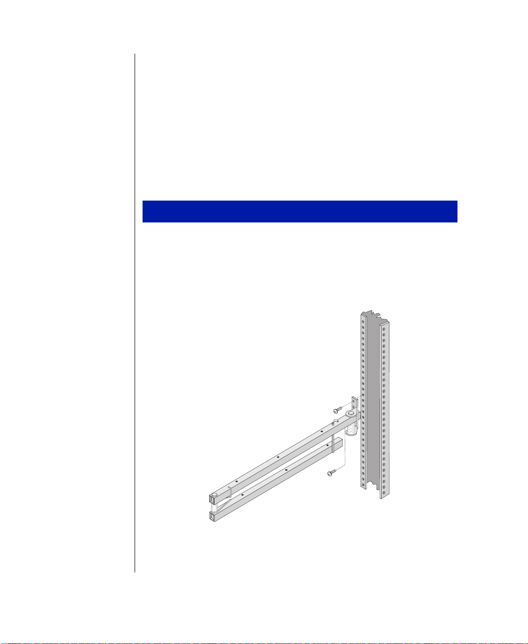
If the mounting rails ha ve not p revi ously been i nstalled , position the
3.
draw er templ ate in the cabinet/r ack so that the side matche s the
corresponding side you wish to install.
Figur e 5: Mountin g the Br ackets on the Cabinet
Mark the screw hole locat ions onto the vertical mounting strips in t he
4.
cabinet, as sho wn on the template. The marks wil l locate the mounting
holes of the rail bracke ts and front panel.
Attach the front bracket t o the front cabinet v ertical mounting strip
5.
using two scr ews. Att ach the rear brack et to the rear cabinet vertical
mounting strip.
Repeat steps 4 and 5 to mount the second rail br acket.
6.
Installing the Processor Drawer 9
Page 20
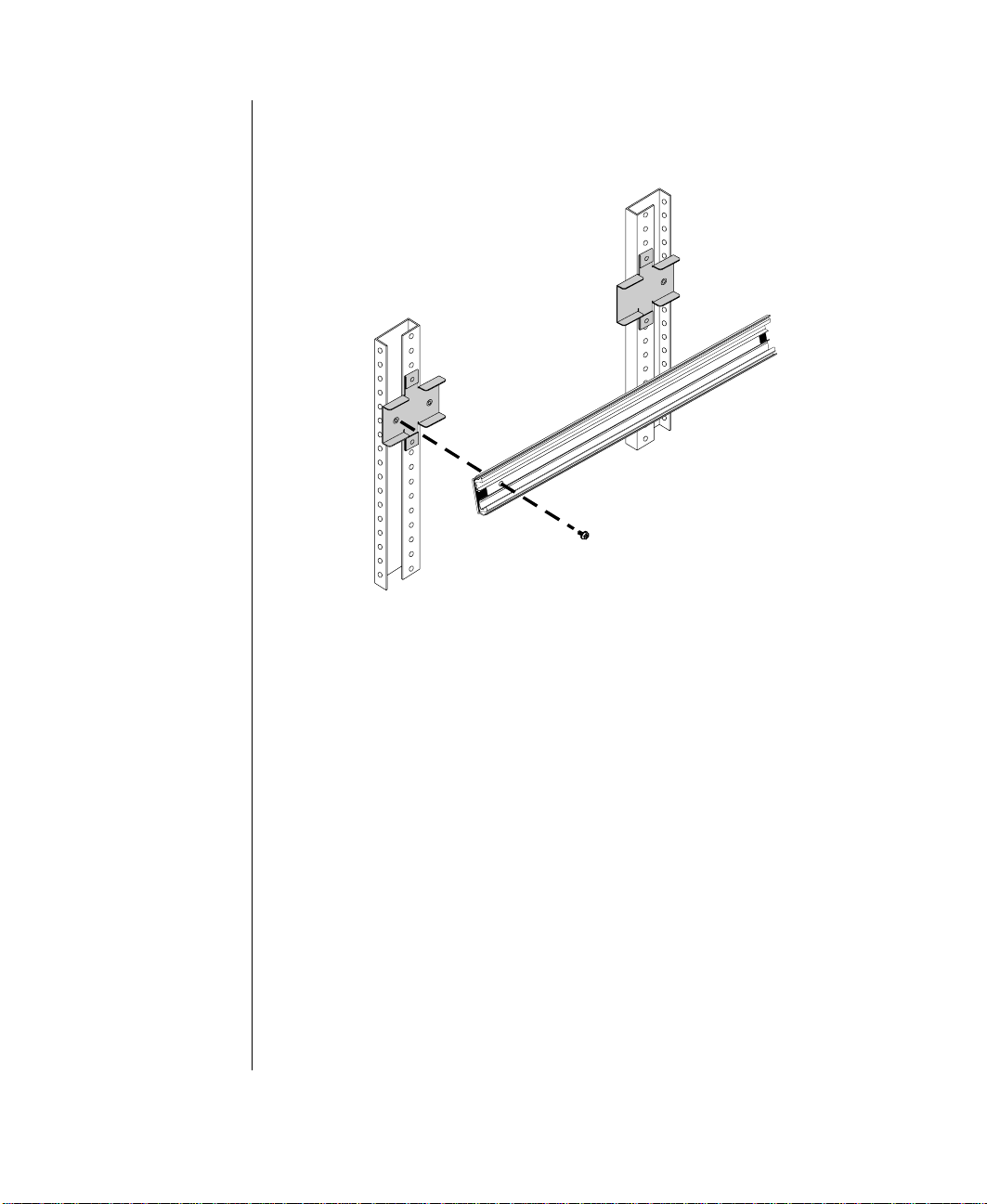
Mount the rail in the rail brack ets using a single screw for e ach end of
7.
the rail. See Figure 6.
Figur e 6: Att aching the Ca binet Mounting Rails
8.
10 Gateway ALR 8200R User’s Guide
T o secure the r ear of the rai l, slide the inner rai ls forwar d to gain
access to the mounting holes. The latch may lock the rail into pl ace.
Release the latch to al lo w the rails to slide freel y. T o secure the front of
the rail, slide the inner ra il so that the opening a ligns with the
mounting holes. Verify that the inner rails slide free ly.
Page 21
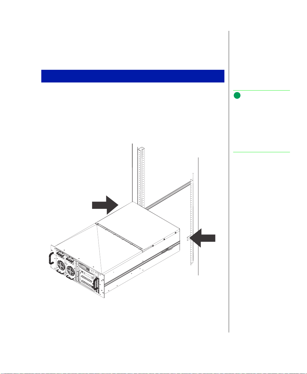
Mounting the Processor Drawer in the Cabinet
After you install t he rails on both the cabi net and the processor dr a wer ,
insert the draw er into t he cabinet.
Mounting the Processor Drawer in the Cabinet
Pull the inner cabinet mounting rails ( in the cabinet) all the wa y
1.
forward until the retaining latches l ock the rails in the “ out” position.
Lift the processor dra w er to the same height as the mounting rai ls and
2.
align the rails on the dra w er wit h the cabinet mounting rails. See
Figure 7.
Note:
The processor drawer is
heavy . To prevent injury and
possible damage to the
equipment, we
recommended that you
have assistance when
trying to mount the drawer
into the cabinet.
Figur e 7: Inst alling the Pr ocess or Dr awer
Installing the Processor Drawer 11
Page 22
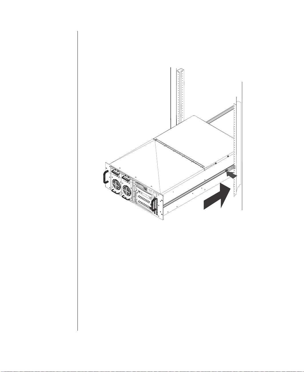
Insert the side rails on the processor dra w er into the cabinet mounti ng
3.
rails and push the dra w er e venl y into the cabinet until the latches o n
the draw er rai ls lock. See Figure 8.
4.
12 Gateway ALR 8200R User’s Guide
Figur e 8: Ca binet Rail Retaini ng Latches
Press the latches on both side ra ils of the processor dr a w er and push
the draw er into the cabinet unti l the front panel touche s the vertical
mounting rails. The dra w er may mo v e reluctantl y at first. How e ver . i t
should mov e smoothl y, without binding or restriction, thereafter .
Page 23
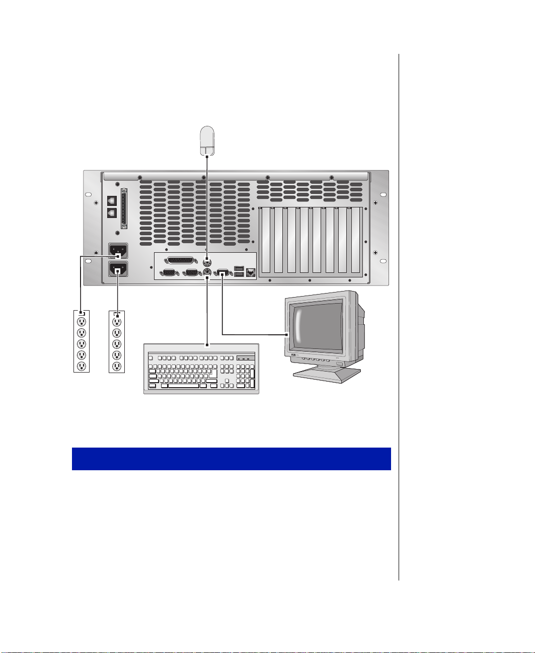
Connecting Peripherals
Refer to Figure 9 and the foll ow ing procedure w hen connecting opti onal
peripherals to your system.
Figur e 9: Connecti ng P er ipher als
Connecting Peripherals
Po w er of f all dra w ers and de vices in t he cabinet prior to at taching an y
1.
of the system dra w er cable s.
Verify that the system draw er pow e r switch is i n the OFF position.
2.
Connect controller and data cab les to their r especti ve de vices as
3.
appropriate (e.g., SCSI cables to QHS Dra wer , or P arallel cab les to
printer , etc.)
Installing the Processor Drawer 13
Page 24

If another system dra w er is insta lled in the same cabinet a nd you wish
4.
to daisy chain them to gether (for the InforManager), connect the ne w
system draw er to t he existi ng dra wer with a RackBus cab le.
Connect the keyboard, mouse and video cables to their respecti ve
5.
ports. Systems with multiple processor dra w ers ma y require
connecting these cabl es to an autosw itcher unit. Refer t o your r ack
system user’s guide or Figure10 on page 15 for proper connections.
Connect the monitor po w er cable to an appropriate po w er sour ce.
6.
Verify that the Voltage Selector Switches on the po w er supplies a re set
7.
for the proper voltage (115V or 230V).
Connect the system po w er cables to the po w er input conne ctors.
8.
Connect the other end of the system po w er cab les to the ap propriate
9.
pow er source s.
Using an AutoSwitcher with Multiple System Drawers
Multiple system dra w ers instal led in the same system cabine t can share a
single set of peripheral de vices (monitor , k eyboar d and mouse). This is
accomplished by using an Auto Switcher .
The AutoSwitcher pro vides ex clusiv e control of the monitor , as w ell as
routes the keyboard a nd mouse inputs to the cu rrently selected syst em
draw er .
14 Gateway ALR 8200R User’s Guide
Page 25
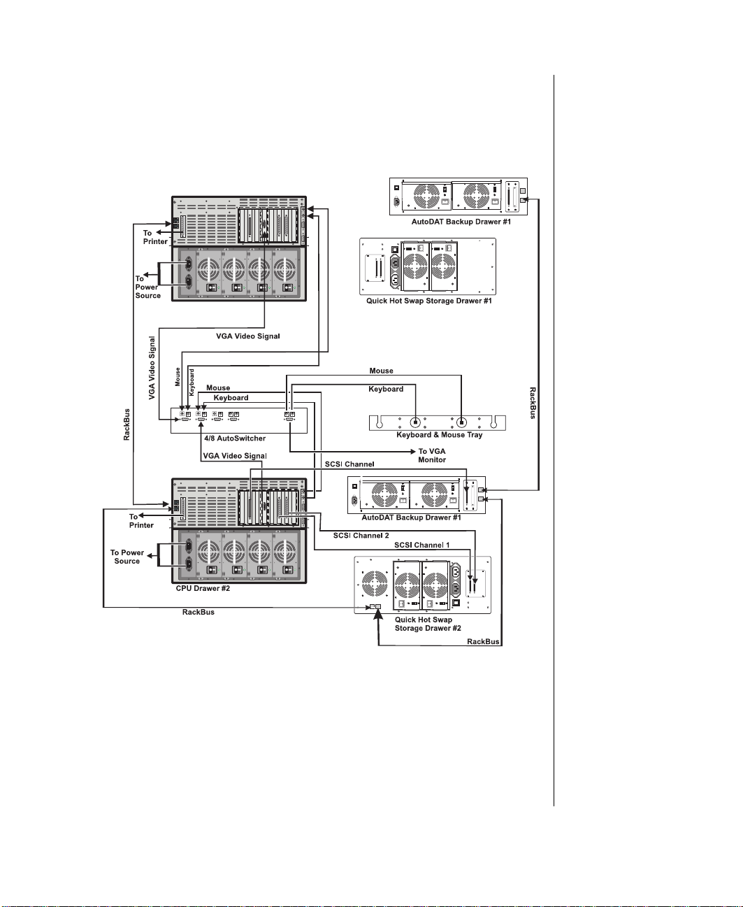
Since the devices t hemselves (that is, the ke yboard, the mouse and the
monitor) are plugged into the AutoSwitcher , connecting the system dra w ers
to an AutoSwitcher requires e xtender cabl es. Refer to F igure 10 for
example connection details .
Figur e 10: Connec ting to an AutoSwi tcher
Installing the Processor Drawer 15
Page 26

Warning!
For safety reasons, the top
cover must be closed and
secured while the system is
running.
Note:
Under no circumstances
return any equipment
without obtaining a Return
Material Authorization
(RMA) number.
P owering Up the System
Press the On/Off switch on the front panel, and the green LED on the front
panel will illuminate ON.
If you turn off th e system, you must w ait at l east ten seconds before you
turn the system back on.
The system self-checks the memory even i f the monitor is not connec ted. If
the monitor is connected and po w ered ON, the scre en displays the pow er -up
sequence.
•
If more than one processor is inst alled , th e system displa ys whic h
processor it is currently testing .
•
If any errors are encountered, your system displays t hem on the
monitor.
•
If a monitor is not connected or th e system is unab le to displa y an
error, an error beep code sounds.
•
If the system encounters an error , it is usual ly nonfatal, meaning
the system functions until the error can be corrected (usuall y
through the BIOS Setup). In the rare case of a fatal error, cont act
your Technical Support for field service support.
Quick Check
If your system does not oper ate correctly, re-read the instructions for the
procedure(s) you ha v e performed. If an error occurs within an application,
consult the documentation supplied with the software.
This section identifies solutions to common problems. If the suggestions i n
this section are not helpful , try calling Technical Support. In the event of a
problem, the follo wing c hecks should be performed:
Looking Things Over
Sometimes, the simplest things can cause troub le. If y ou encounter a
problem, perform the follo win g checks:
16 Gateway ALR 8200R User’s Guide
Page 27

•
Are the pow er c ords connected to the proc essor dra w er and an
appropriate po w er source?
•
Is the pow er source suppl ying po w er?
•
If a pow er stri p is used, is it switched on? Is the circuit break er set?
•
Does the voltage select ion switch on t he system’s po w er suppl y
reflect the proper v oltage?
V erifying Your Configuration
If your system is not ope rating correctly, the BIOS may contain an invalid
configuration parameter. Enter the BIOS pro gram and check your
configuration settings.
Troubleshooting Guidelines
As you troubleshoot t he system, keep the fol lo wing guidelines in mind:
•
Never remo v e the system co v er while the s ystem is po w ered on.
•
Do not attempt to open the monitor , it is e xtremel y dangerous.
Even if the monitor po wer is disconnected , stored ener gy within the
monitor components can cause a painful or harmful shock.
•
If a peripheral such as the k eyboard, mouse, drive, or printer does
not appear to w ork, ensure that all con nections are secur e.
•
If an error message is display ed on the screen, writ e it do wn, w ord-
for-w ord. You may be asked about it when calli ng Technical
Support.
•
Only qualified personnel should open the system for maintenanc e.
•
If you are qualified to maintain the system your self, make certain
you are properl y grounded before opening the syst em chassis.
Powering Up the System 17
Page 28
Completing the Installation
Installing a Cable Retractor
A cable retractor pr o vides the follo wing advantages:
•
Reduced strain on the dra w er cab les and connectors
•
Simplified maintenance because the cables are kept nea tly out of
the way
Installing a Cable Retractor
Position t he cable ret ractor to the rear side of the cabinet so t hat the
1.
mounting holes on both retractor and c abinet are aligned.
Using two scre ws, secur e the cab le retractor to th e mounting holes on
2.
the rear of the system dra w er.
18 Gateway ALR 8200R User’s Guide
Figur e 11: Inst alling a Cab le Retr actor
Page 29
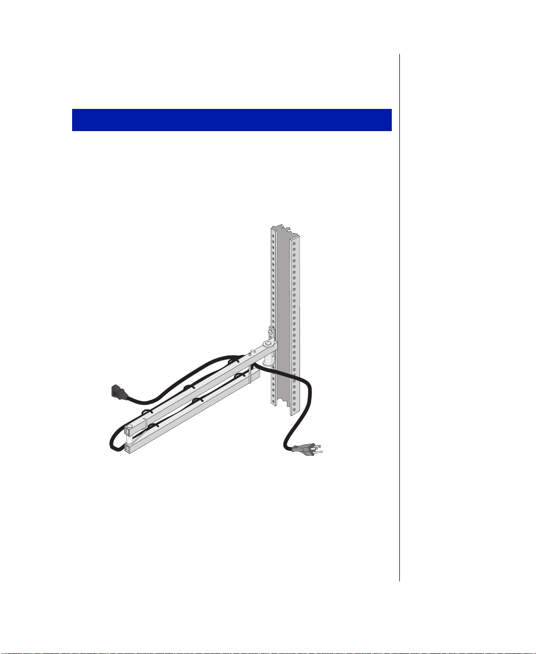
Dressing the Cables
Attach the cables to t he cable ret ractor .
Dressing the Cables
Route the cable(s) fr om the rear of the system drawer ove r to the cab le
1.
retractor , where it i s mounted on the rear of the dra w er .
Secure the cables to t he cable ret ractor with tie wraps ( the cable
2.
retractor is designed with ti e holes to permit installati on of tie wraps).
Figur e 12: Routi ng Cab le on the Cab le Retr actor
Leave e nough slack in the cab les to allo w the m to flex w hen the
3.
draw er is pulle d out.
Check the cables for ti ght spots wh ile the dra w er is being pull ed
4.
forward and pushe d back into place . Check for stress po ints, especiall y
at the bends in the cabl e retractor and w here the cab le retract or is
mounted to the vertical mounting rail.
Powering Up the System 19
Page 30

Route the cables to the ir destinations and se cure with tie wraps as
5.
required.
If necessary , bundle and se cure exces s cable with a tie wrap to ke ep it
6.
out of the wa y.
Securing the System
Physical securi ty for the system is depen dent upon the securi ty pro vided b y
the cabinet.
Securing the System
Close the rear door of the system cabi net and lock if desire d.
1.
Push the system dra wer back until its front panel presses agains t the
2.
vertical mounting rails in the cabinet. Secure the dr a we r with four
screws.
Close the front door and lock if des ired.
3.
20 Gateway ALR 8200R User’s Guide
Page 31

Chapter 2:
System Features
Contents
Basic Features........................................................ 22
Front Panel............................................................. 24
Dual Redundant 400-Watt Power Supplies...24
3.5-inch Diskette Drive.................................. 25
CD-ROM Drive.............................................. 25
LED Indicators............................................... 26
Buttons............................................................ 26
RAID Cage Bay.............................................. 26
Rear Panel.............................................................. 27
I/O Ports.......................................................... 27
Power Connectors ..........................................28
Expansion Slot Cover Plates.......................... 28
System Board......................................................... 29
Chassis Fans.................................................... 30
Power Connectors ..........................................30
Front Panel Connectors.................................. 31
Drive Controllers and Connectors.................32
Server Management Connectors....................33
System Jumpers.............................................. 34
Battery............................................................. 35
Expansion Slots.............................................. 35
I/O Connectors................................................ 35
Processor Subsystem...................................... 36
Memory........................................................... 37
Page 32

Basic Features
•
Support for up to two Inte l P entium® II processors, with dual
16-KB level one ( L1) cache integrated with an additional 512-KB
of level tw o (L2) cache memory
•
SMP design supporting up to tw o processor modules; Inte l MP
Specification V1.1 and 1.4 compliant
•
Autodetection of 66/100-MHz memory bus for all processor
speeds to accommodate processors using either memory bus speed
•
32-bit peripheral component inter connect (PCI) and industry
standard architecture (ISA) bus mast er; 64-bit data path p rocessor
and memory data path; extended PCI-to-PCI brid ge support
•
64-MB Error Checking and Correcting (ECC) memory,
expandable to 1- GB using ECC 60-ns 72-bit synchronous dynamic
random access memory (SDRAM) dual inline memory modules
(DIMMs)
•
Eight expansion slots: five PCI, one shar ed PCI/redundant array of
inexpensiv e driv es- (RAID) port, one shared PCI/ISA, and one
ISA slot
•
Integrated 32-bit dynamic random access memory (DRAM) PCI
Graphics (Cirrus Logic GD54M30) with 2-MB DRAM
22 Gateway ALR 8200R User’s Guide
•
Integrated 10/100 Ethernet port using an RJ-45 connector
•
Integrated PCI Ultra2 small computer system interface (SCSI)
(Adaptec 7890) with tw o 68-pin connecto rs, dual-channel Ultradirect memory access (DMA) PCI integrated dri ve el ectronics
(IDE) interface, and diskette control ler supporting 1.44 MB and
2.88 MB formats.
•
RAIDport ready: the shared PCI/RAIDport slot supports the
addition of a RAIDport card to pro vide RAID capabil ity.
•
Low vo ltage dif ferential (LVD) support for SCSI de vices. LVD
SCSI allows faster disk access and greater data inte grity
•
Po w er suppl y unit that suppo rts dual 400W redundant po w er
supply modules with hot s wap c apability. The system ships with a
single module. If you i nstall the optiona l second module, the po w er
supply supports load sharing and N+1 fault tol erance.
Page 33

•
The system is equipped with InforManage r™ (IFM), a special
feature consisting of both har dware and soft ware designed to
monitor and report the operating status of th e system and its
devices: processors, power supplies, RAM, ambient temperatures,
voltages, and fan operation. For further information about the
InforManager™, refer to the
•
Phoenix upgradable Flash basic input/output system (BIOS), Year
InforManag er™ User’s Guide.
2000 Ready
Basic Features 23
Page 34

Front P anel
The front panel of the system is equipped wit h switches, li ght emitting
diodes (LEDs), and drive bays. See the table be lo w for the ke y to Figur e 13.
Figur e 13: Front Panel
A Power supply fault LED H Hard disk activity LED
B Power supply module 1 I System reset button
C Power supply switch J ECC reset button
D Power supply voltage selection switch K ECC error LED
E Power supply module 2 (optional) L P ower button
F 3.5-inch diskette drive M Power-on LED
G 5.25-inch CD-ROM drive N RAID Cage bay
Dual Redundant 400-Watt P ower Supplies
Po w er is suppli ed to the processor drawer by a dual 400W po w er suppl y
subsystem. This subsystem recei ves its po w er from one or tw o 400W po wer
supplies which are remo v ab le through the front of the system dra w er . The
system ships with a single po w er suppl y module. The second module is
av ailable as an option.
24 Gateway ALR 8200R User’s Guide
Page 35

If both pow er suppl y modules are pr esent, the po w er suppl y system
supports hot-swapping. If one pow er suppl y module fails or b ecomes
inoperative, y ou can change it out without shutting do wn the syst em. The
system continues to recei ve po w er from the remaining po w er supp ly
module while the exchange t akes place.
P ower Supply Fault LED
Each pow er suppl y module is equipped wit h an LED that shines green
during normal operation. If the module exper iences a failure, the LED
shines amber . If the module is not recei ving po w er or has failed complet ely,
the light is of f.
P ower-On Switch
Each pow er suppl y module is equipped wit h a po wer -on s witch that allo ws
you to turn off the module before remo ving it or during maintenance.
V oltage Selection Switch
A voltage selection s witch is locat ed on the upper fron t of each po w er
supply module. These sw itches must be set for the a ppropriate input po w er
(either 110V or 220V).
3.5-inch Diskette Drive
The standard system is equipped with one half-height 1.44-MB 3.5-inch
diskette disk.
CD-ROM Drive
The standard system is equipped with one CD-R OM dri ve.
Front Panel 25
Page 36

LED Indicators
g
g
T abl e 1 sho ws the front panel indi cator LEDs and their funct ions. See
Figure 13 on pag e 24 for the l ocations of the indicator LEDs.
Table 1: Front Panel LED Indicator Lights
LED Meaning When Lit
Power The system is on.
Hard Disk Controller Activity The hard disk is being accessed.
ECC Error An ECC error has occurred.
Buttons
T abl e 2 sho ws the front pane l buttons and their f unctions. See Fi gure 13 on
page 24 for the locati ons of the buttons.
Table 2: Front Panel Buttons
Switch Function
Power Turns the system ON or OFF.
Reset Allows you to reset the system without having to
power it off and then on a
ECC Reset Clears the error flag after an ECC error. Pressing
this button does not correct the error condition. If
the error condition has not been corrected, the LED
ht again.
will li
ain
RAID Cage Bay
The Raid cage bay supports up to three LVD SCA Ultra2 SCSI drives.
These drive can be included as a RAID subsystem or the y can be used
independently. For more information on the dri ves, se e “Installing an
Internal 3.5-inch Device” on page 57 and “Replacing (Hot-Swapping) a
Drive.” on page63.
26 Gateway ALR 8200R User’s Guide
Page 37
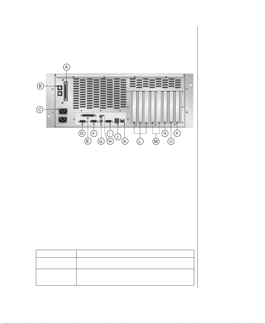
Rear Panel
g
q
The rear panel of the syst em is equipped with I/ O P orts and connectors. See
the table belo w for the ke y to F igure 14.
Figur e 14: Rear Panel
A 68-pin SCSI connector I Video port
B Rackbus connector J Dual USB ports
C Power connectors K Ethernet port
D Serial Port 1 L Primary PCI slots
E Parallel port M Secondary PCI slots
F Serial port 2 N Shared PCI/RAIDport slot
G Keyboard port O Shared PCI/ISA slot
H Mouse port P ISA slot
I/O P orts
The back panel supports the I/O ports through which the system
communicates with the peripherals and a ny other component s in separate
draw ers.
Port Definition
68-pin SCSI
Connector
RackBus
Connector
Provides an external SCSI connection for use with a Tape
e drawer or QHS Storage drawer.
Stora
Allows the processor drawer to be connected to other drawers in
the cabinet e
features.
uipped with hardware management (InforManager)
Rear Panel 27
Page 38

Parallel Port Parallel devices such as parallel printers and scanners can be
g
g
g
connected to this port.
Serial Ports 1 and 2 These are hi
Mouse Port This port supports any mouse with a miniature circular DIN (mini-
Keyboard Port This port supports any keyboard with a miniature circular DIN
Video Port Connects your monitor to the inte
Dual USB Ports Provides connection points for USB-compliant peripheral
Ethernet Port Provides point of connection, via 10/100Base T cable, with
(FIFO) protocol. If you have a serial mouse, connect it to Serial
Port 1 (COM1). Other serial devices such as serial printers or
modems can also be connected these ports.
DIN) connector.
(mini-DIN) connector.
devices, such as modems, keyboards, joysticks, etc.
rated Intel 82258 Ethernet adapter. Allows the system to be
inte
connected to a network.
h speed serial ports which use the First-In-First-Out
rated video controller
P ower Connectors
These connect to a po w er source and pro vide pow er to the po w er suppl y
modules, which distributes power to the system and its periphera ls. Using
the pow er ca bles supplie d with the system, connect each of the po w er
supplies into a separate w all outlet or plug strip.
Expansion Slot Cov er Plates
These are co ver plates f or the corresponding expansion slot s on the system
board: five PCI slots, one PCI/RAID port, one shared PCI/ISA slot, and
one ISA slot.
28 Gateway ALR 8200R User’s Guide
Page 39
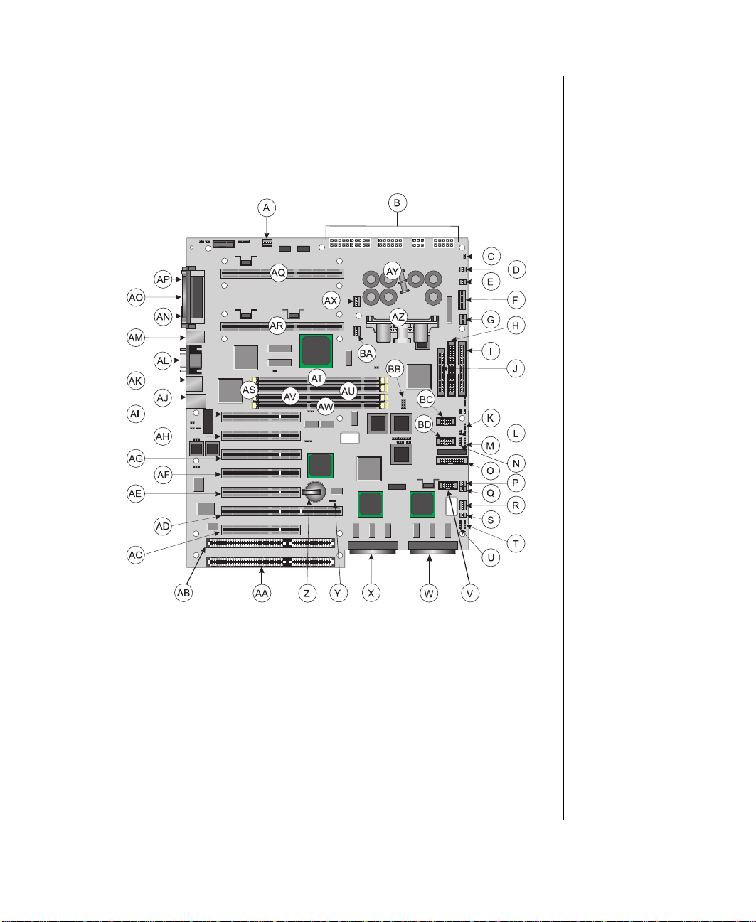
System Board
The system board functions as the main int erface betw een the processor ,
memory , and peripherals. See the table belo w and on t he follo wing page for
the key to F igure 15.
Figur e 15: Syste m Board Components
A Chassis fan connecto r K Front panel connector
B Power connectors L Reset connector
C Standby 3.3-V power connector M External HDD connector
D Soft power connector N HDD LED connector
E P5 fault reset connector O Server management connector
F Power supply auxiliary connector P User NMI connector
G Chassis fan connector Q EDC reset connector
H Secondary IDE connector R Chassis fan connector
I Primary IDE connector S Cover intrusion switch connector
J Diskette con nector T Speake r connector
System Board 29
Page 40

U External boot ROM connector AM Mouse port/keyboard port
2
V
I
C connector
W SCSI B connector AO Parallel port
X SCSI A connector AP Serial port 1
Y Clear CMOS jumper AQ Processor connector 1
Z Battery AR Processor connector 2
AA ISA slot 2 AS DIMM connectors (x4)
AB ISA slot 1 (shared w/ secondary PCI slot 4) AT DIMM bank A
AC Secondary PCI slot 4 (shared w/ ISA slot 1) AU DIMM bank B
AD Secondary PCI slot 3/RAIDport slot AV DIMM bank C
AE Secondary PCI slot 2 AW DIMM bank D
AF Secondary PCI slot 1 AX Processor 1 fan connector
AG Primary PCI slot 3 AY Embedded VRM for processor 1
AH Primary PCI slot 2 AZ Optional VRM for processor 2
AI Primary PCI slot 1 BA Processor 2 fan connector
AJ RJ-45 ethernet port BB Processor setting jumper
AK Stacked dual USB ports BC RAID cage connector
AL Video port BD LED display connector
AN Serial port 2
Chassis F ans
There are sev eral chassis fan connector s on the system board. These
connectors pro vide po w er for cooli ng fans that ma y be positioned i n sev eral
parts of the chassis to pro vide cooling f or critical compone nts.
P ower Connectors
The pow er connectors pr o vide all of t he po w er to the system board. Th ese
connectors are designed to accommodate th e po we r suppl y installed in the
system.
Standby 3.3-V P ower Connector
The 3.3-V standby po w er connector provides connection for a switch to
place the system in standby po w er mode.
Soft P ower Connector
The soft pow er connector pro vides for a po we r swit ch that causes the
system to pow er up or po w er down fr om a standby st ate, rather than
completely shuttin g do wn. This feature is not implemented in this s ystem
30 Gateway ALR 8200R User’s Guide
Page 41

P ower Supply Auxiliary Connector
Provides additional connections from the pow e r supply to the system board.
F ront Panel Connectors
The front panel connector pro vides the signals for the f ront panel indicator
LEDs and the front panel buttons. Not used in the syst em.
P5 Fault Reset Connector
Allows connect ion of a reset s witch for proce ssor fault conditions. This
switch will not reset the processor or remo v e the fault condit ion, it clears
the fault alert flag and causes the fault LED to turn off. If the fault condition
persists, the processor fault LED will turn back on.
Reset Connector
The reset connector pro vides the c onnection of the reset button from the
front panel.
External HDD Connector
The external hard driv e connector all ows y ou to connec t a cable fr om an
external hard driv e to the system board to allo w the hard dri ve activ ity LED
and system monitoring hardw are to reco gnize the e xternal dri ve.
HDD LED Connector
This connector allo ws you to connect all of the hard d ri ves to the hard dr iv e
activity connect or on the front panel.
EDC Reset Connector
The EDC reset connector pro vides the connec tion for a k eyboard lock
button/ECC reset button from the front panel. Not used.
System Board 31
Page 42

Speaker Connector
Connects the internal speaker to the s ystem board.
External Boot ROM Connector
Provides connection for e xpansion cards that contain a separate boot RO M
and require separate access to the system board. This connector is for
factory use only.
LED Display Connector
Connects the LEDs on the front panel to the syst em board. Includes the
keyboard lock button sign als and the reset button si gnals.
Drive Controllers and Connectors
The system board supports sev eral controllers f or driv es and other
peripherals. Cables t o link these controll ers to the appropriate devi ces are
also pro vided.
Hard Drive Controller and Connectors
This is an integrated dual-channel Ultra-DMA PCI/IDE (inte grated dri ve
electronics) interface with tw o IDE connec tors capab le of controllin g up to
four IDE devices and supporting (paging inp ut output) PIO Modes 0-4.
Ultra-direct memory access (DMA) pro vides faster ac cess to IDE de vices
that are Ultra-DMA compliant whi le maintaining support for IDE de vices
that do not support the Ultra-DMA specification.
Diskette Controller and Connector
The diskette dri ve controlle r and connector on the syst em board can support
up to two disk ette dri ves o f 1.44 MB and 2.88 MB formats.
SCSI Controller and Connectors
This integrated Adaptec® AIC™-7890 small computer systems interface
(SCSI) controller is a high-performance, Plug & Pla y (PnP) compliant,
32 Gateway ALR 8200R User’s Guide
Page 43

single-chip PCI local bus-to -Ultra2 SCSI master host adapter. Its advanced
SCSI input/output (I/O) cell tec hnolog y ensures data integrity for hi gher
I/O bandwidth requirements with data rates of 40-MB/sec in Ultra mode
and 80-MB/sec in Ultra2 mode.
Additional features:
•
Dual low v oltage dif ferential ( LVD) 16-bit (68-pin) PCI-to-W i de
Ultra2 SCSI connectors.
•
Full 32-bit PCI bus master implementation maximizing dat a
transfer on PCI local bus at 133 MB/sec data bursts.
•
SCAM (SCSI configured automatically) Le vel 1 for W indo ws95®,
enabling automatic configuration of new de vices without ha ving to
reboot the system.
•
Wide SCSI configuration supporting up to 15 connected SCSI
peripherals per channel for as many as 30 d evices. As man y as
seven 8-bit devices c an be installed on each ch annel.
•
Multi-threading support for up to 255 simultaneous I/O tasks.
•
Advanced SCSI I/O cell ensuring dat a integrity b y automaticall y
and continuously adjus ting sle w rate to compensate f or SCSI bus
loading.
•
Driver support for al l major operating syste ms.
Server Management Connectors
The server management connectors pro vi de hardware an d component
monitoring to assist y ou in maintaining the server .
Server Management Connector
The server management connector allo ws you to connect a server
management device to the system boar d to monitor system acti vities.
Cover Intrusion Switch Connector
Connects a co ver intrusion s witch to the system board s o that the system
can monitor unauthorized access to t he chassis.
System Board 33
Page 44

I2C Connector
This connector is part of the system monitoring. It carries the sig nals of the
2
I
C bus which include identif ying information and status for major system
components.
RAID Cage Connector
The RAID cage connector connects the SCSI backplane to the system
board to allo w status and monitoring of backplane fan acti vity. The signals
provide b ackplane fan tachometer readings. Not implement ed in this
system.
System Jumpers
These jumpers allo w you to set c ertain characteristics of the system. Some
jumpers are reserved and are not descr ibed in this section. Do not change
any jumper unless it i s necessary to configure the system. In some cases,
changing the settings of reserved j umpers can cause damage to t he system
board.
Clear CMOS Jumper
This jumper allo ws you to clea r the CMOS memory . You should only do
this if you cannot access t he normal methods of modifying the CMOS and
modifications to the CMOS are necessary. Cl earing CMOS memory
returns all BIOS Setup settings to the default v alues.
Processor Setting Jumper
This jumper allo ws you to set the spe ed of the processor. Both processors,
in dual processor configurations, must have the same speed rating. If
processors of dif ferent speeds are used i n the same system, the processor s
must run at the speed of the slo w er processor.
34 Gateway ALR 8200R User’s Guide
Page 45

Battery
Provides the po w er to maintain t he CMOS memory when the sy stem is
turned off or unplugged.
Expansion Slots
The system features eight expansi on slots: five PCI slots, one ISA slot, one
PCI/RAIDport, and one shared PCI/ISA slot.
The PCI bus processes peripheral trans actions at a system clock speed o f up
to 33 MHz.
I/O Connector s
The I/O connectors are located on the back pan el of the system. F igure 16
shows the connec tors and the tab le belo w pro vi des the key to the figure.
Caution!
There is a danger of
explosion if the battery is
incorrectly replaced.
Replace the battery only
with the same or equivalent
type recommended by the
manufacturer . Dispose of
used batteries according to
the manufacturer’s
instructions.
Figur e 16: I /O Connectors
A Parallel Port E Mouse Port
B Serial Port 1 F Video Port
C Serial Port 2 G Dual USB Ports
D Keyboard Port H RJ45 Ethernet Port with LED indicators
System Board 35
Page 46

The following I/O connectors are incl uded with the system:
•
Two univ ersal serial bu s (USB) ports:
– USB ports provide connecti on for a growing l ist of
peripheral components including mouse, keyboard , jo ystic k,
monitor, tape and diskette driv es
– As many as 127 de vices can be daisy- chained from each
port
– Hot-sw ap capability and dynamic r esource allocation for all
peripherals attached
– Data transfer rates of up to 12Mbps.
–
USB drivers are pro vided as a part of most major operating
systems and should require no special procedures for
implementation or use.
•
Two 9-pin 16550-compatib le serial ports
•
One bi-directional ECP/EPP parallel port
•
One VGA vide o port
•
One PS/2-style mouse port
•
One PS/2-style keyboard port
Processor Subsystem
The system board supports as many as tw o process ors (CPUs). The board
provides sev eral additiona l connectors for supporting components, a s
described in the follo wing paragraphs.
Processors and Processor Slots
Depending on the model, the system is equipped with one Intel P entium® II
processor with 512-KB ECC L2 cache integrated into a single edge contact
(SEC) cartridge.
36 Gateway ALR 8200R User’s Guide
•
One RJ-45 Ethernet connector with two LED indicators. The green
LED indicates a communication link has been estab lished with the
network and the yello w ind icator sho ws that th e communication is
occurring at 100 Mbps when on and at 10Mbps when of f.
Page 47

The system SMP design supports up to two processors and is Intel MP
Specification v1.1 and 1.4 compliant.
Processor Fan Connectors
The processor fan connectors pro vide power for the fans mounted on the
processor heatsinks. These fans cool the processors and pre vent
ov erheating. Note tha t not all processor he atsinks ha ve or need fans. If the
processor heatsink includes a fan, connec t it to the correct fan connector .
V oltage Regulator Modules
Each processor must ha ve a dedicate d voltag e regulator module (VRM)
that adjusts the vol tage supplied to the pr ocessor . The VRM for the first
processor (CPU 1) is embedded on t he system board. The VRM for the
second processor (CPU 2) is placed in t he pro vided connector when the
second processor is installe d.
Memory
The system comes standard with 64 MB of ECC RAM. System RAM is
expandable up to 1 GB using ECC 60ns 72-bit synchronous DRAM
(SDRAM) DIMMs (4 DIMM sockets).
System Board 37
Page 48

38 Gateway ALR 8200R User’s Guide
Page 49

Chapter 3:
Components
Contents
Processors.............................................................. 40
Installing a Pentium II Processor................... 41
Installing A VRM (for Processor 2).............. 44
Changing the Processor Speed....................... 45
System Memory ....................................................46
Configuring Your Memory............................ 46
Installing DIMMs........................................... 47
Adapter Cards........................................................ 49
Storage Bays.......................................................... 51
Removing the Drive Bay Assembly.............. 52
Removing the 5.25-inch Device.................... 53
Installing a 5.25-inch Device......................... 54
3.5-inch Devices............................................. 55
RAID Bay....................................................... 58
Page 50
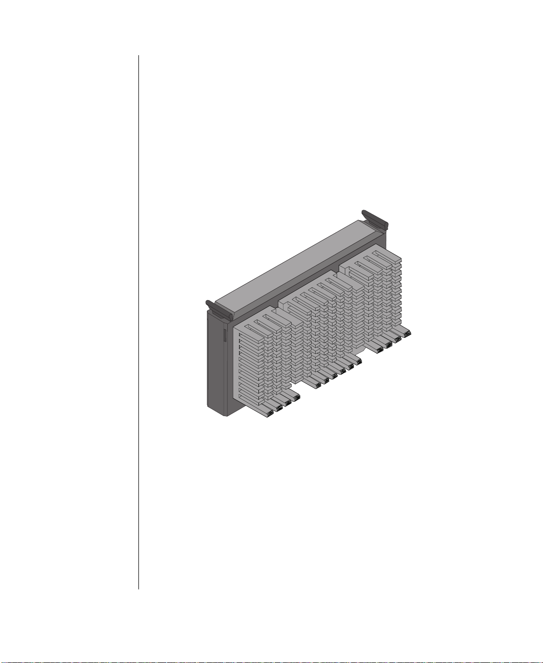
Processor s
Your system has been designed for the P ent ium® II processor . Ho we ver , the
system can be enhanced with v arious options to mee t your futur e needs,
such as installing a second proce ssor . This chapter pr o vides procedures to
assist you in insta lling some of these options . F or more information about
av ailable options for y our system, contact y our reseller or Gatew a y Sales.
Your system supports a second processor to further enhance system
performance. Processor Upgrade kits are readil y av ailab le at y our reseller.
40 Gateway ALR 8200R User’s Guide
Figur e 17: P enti um II Processor
Page 51

Installing a P entium II Processor
Installing an additional P enti um II processor or replac ing your existing
processor cartridge with a faster model can increase performance.
Installing a Pentium II Processor
If replacing an exist ing processor , remo v e the processor ret aining bar
1.
from the connector by r emo ving the tw o scre ws that sec ure it.
Gently pull out the p rocessor cartridge fr om the support bracket and
2.
save the it for future use.
Figur e 18: Remo ving the Exi sting Pentium II Processor
Processors 41
Page 52
If you are adding a second processor , remo v e the terminator card at
3.
processor connector #2.
Figur e 19: Remo ving the Terminator Card
Remove the new processor cartridge fr om its protecti ve pack aging.
4.
5.
42 Gateway ALR 8200R User’s Guide
Align the new processor cartridge with the guides on the support
bracket and push the cartridge into the processor connec tor .
Page 53

Figur e 20: Ins talling the Pentium II Processor
Verify that the processor cartridge is firmly seated and lock it into
6.
place by replacing the retaining bar y ou remo ved in s tep 1.
If you upgraded processor 1, then go directl y to “Changing the
7.
Processor Speed” on page 45.
If you upgraded processor 2, then continue on to the ne xt
section,“Installing A VRM (for Processor 2)” on page 44.
Processors 43
Page 54

Note:
The VRM for processor 1 is
integrated on the system
board. Install a VRM only if
installing a second
processor.
Installing A VRM (for Processor 2)
Each processor requires a VRM to set the incoming volt age lev el for the
processor . The VRM for processor 1 is integrated into the syst em board. A
socket is pro vided to accommodate t he VRM for processor 2. When you
install a second processor , y ou must also inst all a VRM.
Installing a VRM
Open the system and locate the VRM socket on t he system board.
1.
(See “System Board” on page 29.)
44 Gateway ALR 8200R User’s Guide
Figur e 21: Inst alling a VRM
Page 55
Remov e the ne w VRM from its packaging.
2.
Hold the new VRM o v er the VRM socket an d verify that t he pins on
3.
both VRM and socket are aligned.
Gently insert the new VRM into the socket and push in unti l it latches
4.
into place.
Proceed to “Changing the Processor Speed” on page45 below .
5.
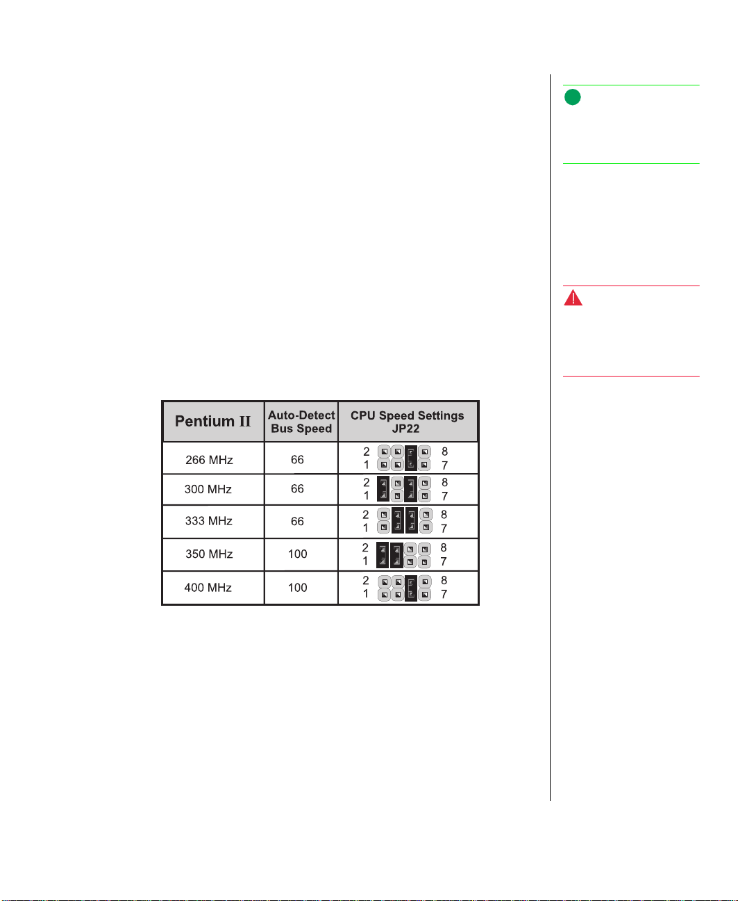
Changing the Processor Speed
Note:
Both the VRM and the
socket are ke y ed t o pre v ent
improper connection.
If you upgrade the process or(s), you must change the processor clock spee d
jumper settings as w ell. The follo wing tab le sho ws the pr oper jumpers
settings for the processor y ou ha ve s elected.
Table 3: Processor Speed Jumper Settings
After you ha ve changed the jumper settings, reinstal l the top co ver a nd
pow er up the system.
Warning!
Running the processor at a
speed higher than it is rated
for will cause irreparable
damage to your system.
Processors 45
Page 56

System Memory
Note:
The Pentium II only
supports 512MB of
memory.
The system comes standard with 64-MB of ECC memory. Total system
memory is upgradable to 512-MB using 60-ns 72-bit DIMMs (four DIMM
sockets). When adding RAM to your sys tem, use only Gate w a y-appro ved
DIMMs.
Configuring Your Memory
Refer to the table be lo w to configure your RAM correctly.
Total DIMM Socket 1 DIMM Socket 2 DIMM Socket 3 DIMM Socket 4
RAM T yp e Size Type Size Type Size Type Size
32 2x72 16MB 2x72 16MB -- -- -- -32 4x72 32MB -- -- -- -- -- -48 2x72 16MB 2x72 16MB 2x72 16MB -- -48 2x72 16MB 4x72 32MB -- -- -- -64 2x72 16MB 2x72 16MB 2x72 16MB 2x72 16MB
64 4x72 32MB 4x72 32MB -- -- -- -64 4x72 32MB 2x72 16MB 2x72 16MB -- -64 8x72 64MB -- -- -- -- -- -96 8x72 64MB 4x72 32MB -- -- -- -96 8x72 64MB 2x72 16MB 2x72 16MB -- -96 4x72 32MB 4x72 32MB 2x72 16MB 2x72 16MB
128 16x72 128MB -- -- -- -- -- -128 8x72 64MB 8x72 64MB -- -- -- -128 8x72 64MB 4x72 32MB 4x72 32MB -- -128 8x72 64MB 4x72 32MB 2x72 16MB 2x72 16MB
192 16x72 128MB 8x72 64MB -- -- -- -192 16x72 128MB 4x72 32MB 4x72 32MB -- -192 16x72 128MB 4x72 32MB 2x72 16MB 2x72 16MB
192 8x72 64MB 8x72 64MB 8x72 64MB -- -192 8x72 64MB 8x72 64MB 4x72 32MB 4x72 32MB
256 32x72 256MB -- -- -- -- -- -256 16x72 128MB 16x72 128MB -- -- -- -256 16x72 128MB 8x72 64MB 8x72 64MB -- -256 8x72 64MB 8x72 64MB 8x72 64MB 8x72 64MB
384 32x72 256MB 16x72 128MB -- -- -- -384 16x72 128MB 16x72 128MB 16x72 128MB -- -384 16x72 128MB 16x72 128MB 8x72 64MB 8x72 64MB
512 32x72 256MB 32x72 256MB -- -- -- -512 32x72 256MB 16x72 128MB 16x72 128MB -- -512 32x72 256MB 16x72 128MB 8x72 64MB 8x72 64MB
512 16x72 128MB 16x72 128MB 16x72 128MB 16x72 128MB
46 Gateway ALR 8200R User’s Guide
Page 57

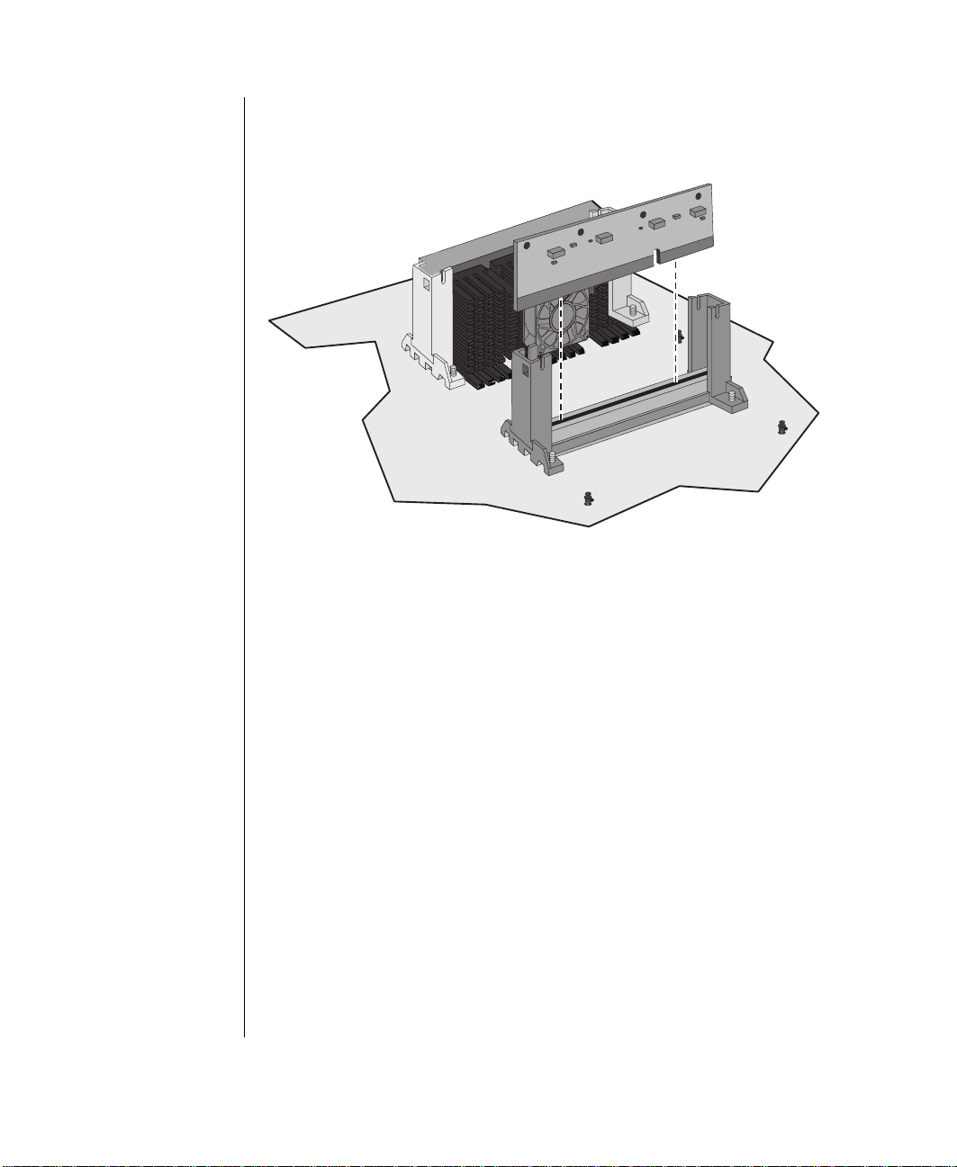
Installing DIMMs
You can expand the memory in the sys tem by instal ling additional or l arger
capacity DIMMs.
Installing DIMMs
Remove the top co ver.
1.
If upgrading an existing memory module, remo ve the DIMM b y
2.
pushing the retaining latches a w a y from each othe r . Pull out t he
DIMM and store it for future use.
Figur e 22: Remo ving an Original DIMM
System Memory 47
Page 58

Note:
The DIMM units are key ed
to align with the DIMM
sockets.
Insert the (upgrade) DIMM vertically int o the socket as shown in
3.
Figure 23.
Warning!
For safety reasons, the top
cover must be closed and
secured while the system is
running.
Figur e 23: Ins talling Memory
Push the DIMM into the socket unti l it is firmly seated.
4.
Lock the DIMM into place by p ushing the retai ning latches to w ards
5.
each other .
Repeat steps 3 through 5 to install additional DIMMs.
6.
Reinstall the top co ver as previo usly described and po w er up the
7.
system.
48 Gateway ALR 8200R User’s Guide
Page 59

Adapter Cards
T o protect ada pter cards from st atic electricit y:
•
Before removi ng the card from its ant i-static bag, dischar ge static
electricity from your body b y touch ing the metal cabine t of any
electrical equipment (the equi pment must be plugged into a
grounded outlet).
•
Alw ays hol d a card or board b y its edges .
•
Do not rest the board on an y static-generati ng surface, such as
carpeting.
Installing Expansion Cards
1.
Remove the top co ver.
2.
Locate an av ailab le expansion s lot (ISA or PCI) on the system boa rd.
3.
Use a Phillips scre wdriv er to remo v e the scre w that secures the co ver
plate of the slot y ou hav e selected. Sav e the scre w.
Adapter Cards 49
Page 60

Insert the adapter card into the slot a nd push in until the card is firmly
4.
seated. If you are instal ling a full-size ca rd , make certain it aligns wi th
the card guide. (See Figure 24.)
Warning!
For safety reasons, the top
cover must be closed and
secured while the system is
running.
5.
6.
50 Gateway ALR 8200R User’s Guide
Figur e 24: Inst alling an Adapter Car d
Secure the card with the scre w you remo v ed in step 2. Doub le-check
the card , making sure i t is seated correctly.
Reinstall the top co ver and po w er up the system.
Page 61

Storage Bays
The system can support up to sev en devices in the follo wing ba ys :
•
Three 3.5-inch devices : one external ba y with a factory-installed,
1.44-MB 3.5-inch diskette dri ve and two internal mounting
brackets
•
One 5.25-inch front accessible bay t hat will support any 5.25-inch
device or an y 3.5-inch de vice with a spec ial mounting bracket
•
RAID bay whic h supports up to three 3.5-inch LVDSCA dri ves
Refer to the specific section that corresponds to the type of device y ou are
installing.
A
B
E
C
D
Figur e 25: Additi onal Device Options
A Internal 3.5-inch drive mounts D RAID Cage (three 3.5-inch L VD SCA drives)
B 3.5-inch diskette drive (installed) E 400 W hot-swap power supplies
C 5.25-inch drive bay (CD-ROM installed)
Storage Bays 51
Page 62

Removing the Drive Ba y Assembly
Before you can install , remo ve, or rep lace a de vice in the dri ve ba y
assembly, you must remo ve the entire assembl y from the dra w er . Driv es that
are housed in the dri ve ba y assemb ly in clude the 3.5-inch di skette dri ve, the
5.25-inch CD-ROM dri ve, and the 3.5-inch dri ves in the RAID Cage bay.
The instructions for remo ving these dri v es will refer to thi s section.
Removing the Drive Bay Assembly
T urn the system pow er off.
1.
Open the system by remo ving the top co ver.
2.
Unplug the data and po w er cable s to all de vices in the dri ve bay
3.
assembly.
Remove the six scre ws that secure the dri v e bay a ssembl y to the
4.
bottom of the draw er.
52 Gateway ALR 8200R User’s Guide
Figur e 26: Remo ving the Drive Bay As sembly
Page 63

If necessary , remove the five scre ws that secure the a ssembl y to the
5.
front of the dra w er .
Pull the entire assemb ly back a w a y from the front p anel and gentl y lift
6.
it out of the dra w er . Be careful not to damage any component s on the
assembly i tself or around the cool ing fans behind it as y ou remo ve i t.
Place the assembl y on a stati c free surface.
7.
Removing the 5.25-inch De vice
The draw er has onl y one 5.25-inch dri v e bay. This bay normall y contains a
CD-ROM dri ve. If y ou want to r eplace the CD-R OM dri ve with a nother
device, you must first remov e the exi sting CD-R OM dri ve.
Removing the 5.25-inch Device
T urn the system po w er of f.
1.
Open the system by remo ving the top co ver.
2.
Remove the driv e ba y assembl y. See “Removing the Dri ve Ba y
3.
Assembly” on page52.
Press the tabs on the front end of the driv e rails in to w ard the c enter of
4.
the drive and pull the dri ve from the dri ve ba y assemb l y.
Figur e 27: Remo ving the CD-R OM Drive
Remove the driv e rails for use on the replacement de vice.
5.
Storage Bays 53
Page 64
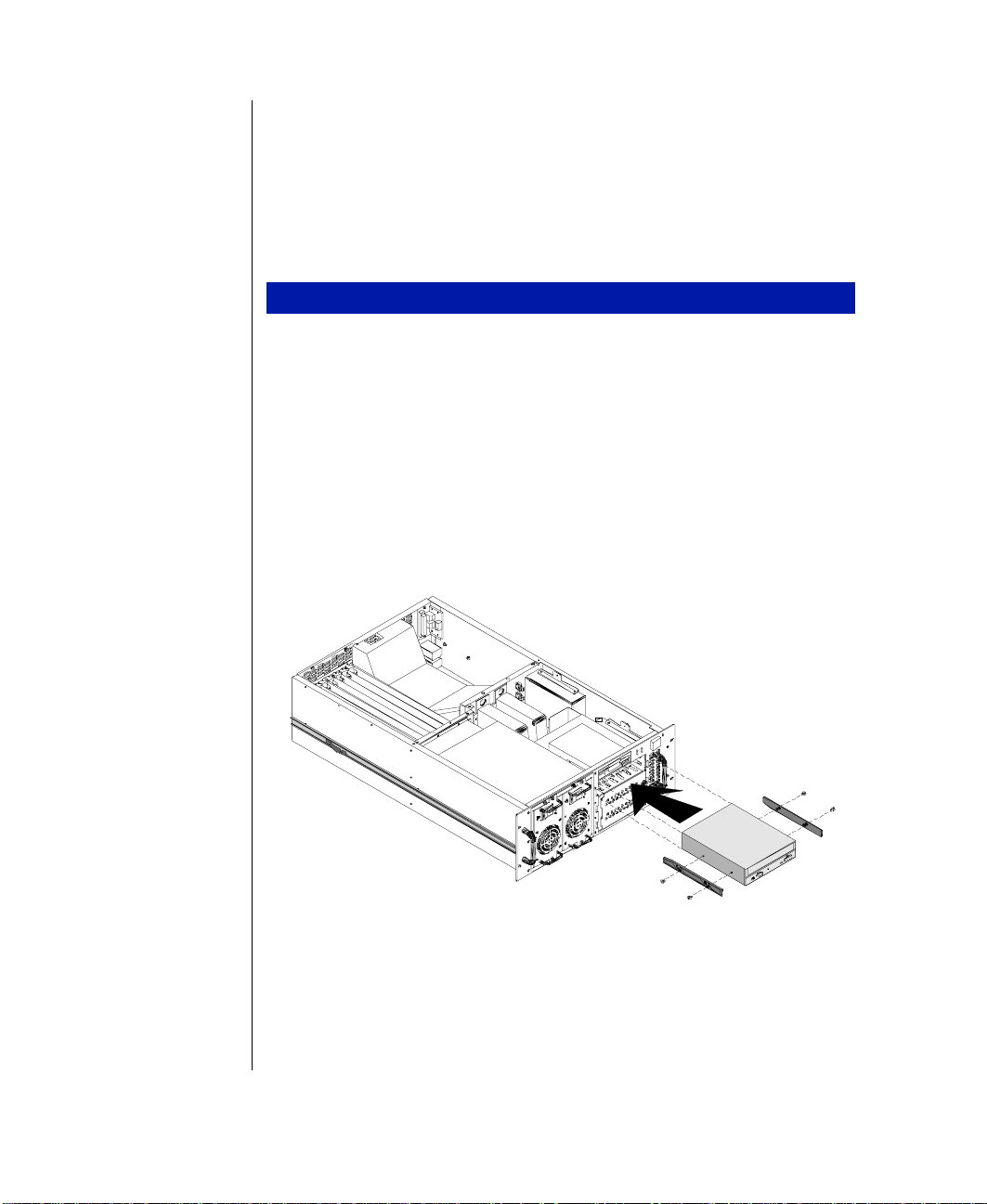
Installing a 5.25-inch Device
If a device alre ady occupies the 5.25-inch dr iv e bay, remov e it before
installing the replacement dri ve (se e “Removing t he 5.25-inch Devi ce” on
page 53). If the 5.25-inc h driv e ba y is empty, remove the RF shield t hat
cov ers it.
Installing a 5.25-inch Device
T urn the system pow er off.
1.
Open the system by remo ving the top co ver.
2.
If no 5.25-inch device is cu rrently installed, remove the metal RF
3.
shield that protects the 5.25- inch device bay.
Attach mounting rails to the 5.25-inch de vice.
4.
From the front of the chas sis, insert the dri ve into the bay.
5.
6.
54 Gateway ALR 8200R User’s Guide
Figur e 28: Inst alling a 5.25-inch Dr ive
Connect the device cab le to the de vice, making sure that pin 1 on both
cable and de vice are aligned.
Page 65

Locate the diskette connect or or hard dri ve connector on the system
7.
board (depending on the de vice yo u are installing).
Connect the drive c able to the c orresponding connector on the system
8.
board , making sure to match pin 1on bot h system board and dri ve
connectors. On most standard cab les, pin 1 is desi gnated by a c olored
wire on the cable. In some cas es, the devi ce connector is ke yed.
Connect the device to t he po w er supply using an a va ilable po w er
9.
connector .
Reinstall the top co ver and po w er up the system.
10.
Warning!
For safety reasons, the top
cover must be closed and
secured while the system is
running.
Enter the BIOS Setup program b y pressing
11.
Enter the appropriate configuration information in BIOS Setup, then
12.
before the system boots.
F
2
reboot the system.
3.5-inch Devices
The system draw er supports as man y as six 3.5-inch de vices. The major ity
of these devices are e xpected to be hard dr iv es. Ho we ve r , the system ships
with a 3.5-inch diskette dri ve as w ell.
Replacing the 3.5-inch Diskette Drive
The system ships with a standard 1.44 MB capac ity 3.5-inch disk ette dri ve.
If this driv e fails and must be replac ed , foll ow the instructions belo w.
Replacing the 3.5-inch Diskette Drive
T urn the system po w er of f.
1.
Open the system by remo ving the top co ver.
2.
Remove the driv e ba y assembl y (see “Remo ving the Driv e Bay
3.
Assembly” on page52).
Remove the four scre ws securing the dri ve onto the t op of the dri ve
4.
bay assemb ly.
Storage Bays 55
Page 66
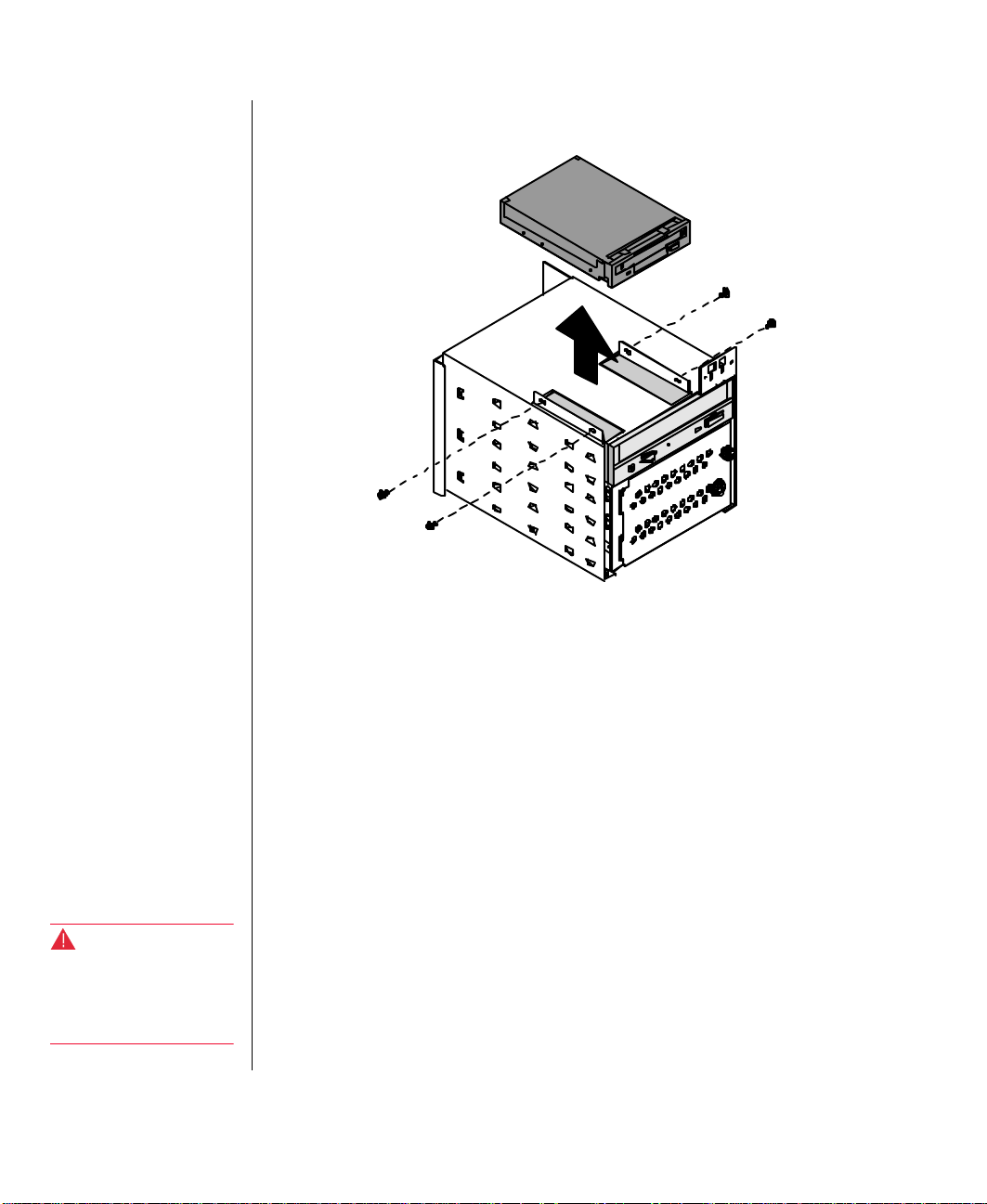
Remove the driv e from the dri ve ba y assemb ly.
5.
Figur e 29: Remo ving a 3.5-inc h Drive
Install the new dr iv e into the dri ve ba y and sec ure with the scre ws
6.
removed in step 4.
7.
8.
9.
10.
Warning!
For safety reasons, the top
cover must be closed and
secured while the system is
operating.
56 Gateway ALR 8200R User’s Guide
11.
12.
13.
Replace the driv e ba y assembl y.
Connect the drive ca ble to the dr iv e, making sure that pin 1 on bot h
cable and dri ve are ali gned.
Locate the diskette connect or on the system board (see F igure15 on
page 29).
Connect the drive ca ble, making certain to match pi n 1 on both
connectors. On most standard cab les, pin 1 is desi gnated by a co lored
wire on the cable. In some cas es, the connector is k ey ed.
Connect the driv e to the po w er suppl y, using an ava ilable po w er
connector .
Reinstall the top co ver and po w er up the system.
Enter the BIOS Setup program b y pressing
before the system boots.
F
2
Page 67

Enter the appropriate dri ve information in BIOS Setu p, then reboot the
14.
system.
Installing an Internal 3.5-inch Device
There are two 3.5-inch dri ve mounting bra ckets inside the processor dra w er
that are not accessible from the outside of the sys tem. These brackets are
intended for mounting 3.5-inch hard dri ves or si milar devi ces.
Installing an Internal 3.5-inch Device
T urn the system po w er of f.
1.
Open the system by remo ving the top co ver.
2.
Install the mounting bracket s (2) onto the de vice with th e scre ws
3.
supplied.
Figur e 30: Inst alling an Internal 3.5-inc h Device
Storage Bays 57
Page 68

Warning!
For safety reasons, the top
cover must be closed and
secured while the system is
operating.
Connect the data cable to the de vice, making sur e that pin 1 on both
4.
cable and de vice are aligned.
Locate the appropriate connector on the system board (depending on
5.
the device you ar e installing).
Connect the data cable, making certain to match p in 1 on both
6.
connectors. On most standard cab les, pin 1 is desi gnated by a co lored
wire on the cable. In some cas es, the connector is k ey ed.
Connect the device to t he po w er supply, using an av ailab le po w er
7.
connector .
Install the dri ve b y aligning the tw o pi ns on the bottom dri ve bra cket
8.
with the corresponding holes in the chassis mounting bra cket.
Secure the driv e to the chassis b y inst alling a scre w through the top
9.
drive brac ket into the corresponding hole in t he chassis.
Reinstall the top co ver and po w er up the system.
10.
Enter the BIOS Setup program b y pressing
11.
Enter the appropriate dri ve inf ormation in BIOS Setup, then reboot t he
12.
before the system boots.
F
2
system.
RAID Bay
The RAID bay is a reliab le, fault tolerant netw ork storage solution t hat
supports RAID levels 0, 1, and 5 and accommodat es up to three 1-inch or
1.6-inch high 3.5-inch LVD SCA drives . F or optimum operation, us e only
approv ed , RAID-Ready dri ves wit h the RAID ba y.
The RAID bay allo ws y ou to easil y configure a reliable RAID subsystem.
Drives are mount ed on a rail system, w hich pro vides quick and ea sy
installation, as w ell as hot-s w apping capability. A fully functional RAID
subsystem is controlled b y a Caching Controll er .
Hot-swapping is a useful feature t hat allo ws y ou to replace failed hard disk
drives without i nterrupting system operation. In the ev ent of a hotswappab le dri ve failure, w hich is part of a RAID 5, the system continues
normal operations. The failed driv e is replaced, and its contents rebuilt
automatically on an e quiv alent repl acement dri ve, without interrupting the
operation of the system.
58 Gateway ALR 8200R User’s Guide
Page 69

For i nformation on RAID components and a vailab le upgrade kits, contact
your reseller.
The RAID bay gi ves y ou greater fle xibility w hen you ar e installing both t he
SCSI hard disk drives and a SCSI CD-R OM. Also, you can daisy chain a
device to the RAID Cage with an i ndustry-standard 50-pin connector SCSI
cable, while maintaining the 68-p in connector fast/wide cab le to the
controller . Refer to the follo wing page for ju mper locations on the RAID
bay backplane.
C
JP2
JP3
D
E
JP1
JP8
JP9
B
JP5
JP6
JP7
A
L
JP4
K
J
JP10
I
H
JP11
F
G
Figur e 31: RAID Bay Bac kplane
A DC power G 8-bit terminator
B 50-pin SCSI connector H 68-pin SCSI connector
C Auto start/delay start I Termination power
D 16-bit active terminator J Cluster option
E Lower SCSI ID address or 0, 1, 2, or 4, 5, 6 K Fan connector
F Upper SCSI address 8,9,10 or 12,13,14 L Fan tachometer connector
Storage Bays 59
Page 70
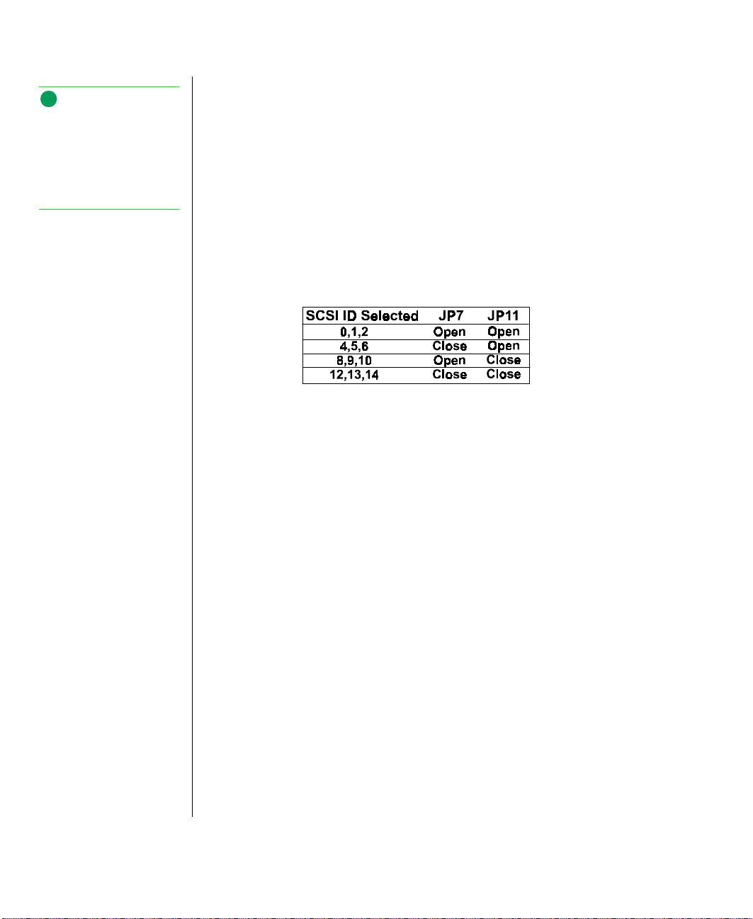
Note:
Each drive should have a
drive number label affixed
to the front of it. The driv e
number on the label should
correspond to the SCSI ID
of the device.
SCSI ID Address Settings
Up to fifteen devices can be connected to a single SCSI channel. Each
SCSI device is assigne d a SCSI ID number (address). The acti ve backpla ne
of the RAID bay allo ws t he user to assign SCSI ID numbers for each of the
drives i nstalled , based on the jumper setti ngs of JP7 and JP11. Dri ves
should be installed in the lowest ava ilabl e driv e ba y. Refer to T able 4 f or
specific jumper settings. SCSI ID’s are assigned from each dri ve’s position
in the RAID bay (from l ow est to highest).
Table 4: SCSI ID Selection Jumpers
Active Termination
Every SCSI subsystem must be terminated at both ends for proper
operation. Refer to the documentation supplied with yo ur controller for
instructions on how to pr operly te rminate your control ler . Terminate the
other end of the SCSI subsystem b y setting JP8, and/or JP3 on the RAID
Cage backplane. These jumpers pro vide acti ve termination on the SCSI
bus. JP6 provide s termination po w er for the 8-bi t, 50-pin connector at th e
top to the RAID cage and JP3 pro vides ac tiv e termination for the 16-bi t, 68pin Ultra2 Wide SCSI connector . Acti ve termination is enabled b y
removing th e jumper from JP6 (Standard SCSI) or JP 3 (Ultra W ide SCSI).
T erminat ion po w er is pro vided b y JP10. To enable termination pow er ,
jumper pins 1 and 2 of JP10. To disable termination pow er , jumper pins 2
and 3 of JP10.
60 Gateway ALR 8200R User’s Guide
Page 71

Connecting the Cables
The SCSI backplane comes from the factory with cables connected.
How ev er , if you ev er need to reconnect an y cable s or to replace or install the
backplane, follo w the directi ons belo w.
Connecting the Cables
A single cable is used and termination must be enabled (jumper
1.
remov ed from JP3) for the system to operate properl y.
Plug one end of the SCSI cable into t he RAID Ba y and the other end
2.
into the RAID SCSI controller, which controls the RAID bay. Be sure
to enable the termination on this channel.
Reinstall the top co ver.
3.
Po w er -up the system and instal l any de vice dri v ers required b y the
4.
SCSI controller for your operating system. Follow the instructions in
the documentation t hat came with your SCSI c ontroller for more
information on setting up the SCSI controller .
Install the hard disk dri ves as sho wn in “Installin g the Driv es” on
5.
page 61.
Installing the Drives
The RAID bay accommodates up to th ree LVD SCA driv es. Dri ves are
mounted on a rail system that allo ws quick and easy install ation, and hotswapping.
Installing the Drives
Label the SCSI Channel and the SCSI ID numbers on the fr ont of the
1.
drive.
Warning!
For safety reasons, both
upper and lower bezel
doors must be closed and
locked while the system is
running.
Note:
Each drive has a Drive
Number label affixed to the
front of the drive. The drive
number on the label
corresponds to the device’s
SCSI ID. Drives must be
installed in ascending order
starting from the bottom bay.
Storage Bays 61
Page 72
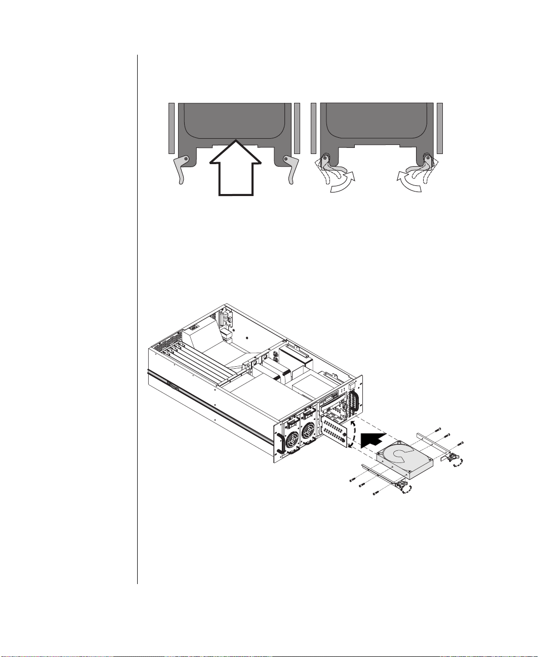
Starting from the bottom of the driv e cage, unlock the dri ve’s latching
2.
clips by s winging them out.
Figur e 32: I nstalling the Dri ve
Align the driv e rails with the dri v e cage guides.
3.
Slide the driv e in until it mak es contact with the conne ctor at the rear
4.
of the cage.
5.
62 Gateway ALR 8200R User’s Guide
Figur e 33: Instal ling an SCA Drive
Press firmly until the dr iv e seats in the connector. The locking tabs lift
aw a y from the face of t he front panel and swing inw ard w hen the dr iv e
is seated.
Page 73

After installation, initialize the drives in the RAID Cage following the
instructions that came with your SCSI control ler . Be sure t o follo w the
SCSI controller instructions on how to opera te the RAID system, especially
about how to properl y hot-sw ap a hard dis k driv e, to pre vent inadv ertent
corruption of your data.
Replacing (Hot-Swapping) a Drive.
If one of the driv es fails and y ou are running a RAID le vel that suppo rts
hot-swappi ng, you can repla ce the failed driv e without po w ering do wn the
system.
Hot-Swapping Drives
Remove the replacement dri ve from i ts shipping carton and inspect it
1.
carefully.
Open the RAID Bay door on the f ront of the system.
2.
Record the SCSI ID number of the dri ve y ou are repl acing.
3.
Select the matching SCSI ID Number Label (pro vided with t he new
4.
drive) an d affix it to the front of the ne w devic e.
If replacing the failed dri ve w hile the system is running, place the
5.
failed drive off-li ne first This may be accomplished automat ically i f
your system is set up for enhanced RAID lev el 5 operation. Otherwis e,
you must run the software.
Caution!
Before replacing a drive,
verify that you are properly
grounded, or static
electricity may damage the
device.
Note:
The ID for the
replacement drive is set
automatically when the
drive is installed in the
slot of the failed driv e .
Remove the failed dri ve b y swinging the locking tabs outw ard and
6.
sliding the dri ve to w ard you.
Align the new dri ve with t he rail guides and gentl y push the dri ve int o
7.
place.
Swing the locking tabs inw ard to secure the dri v e in its ba y.
8.
Close and lock the RAID Bay d oor .
9.
Storage Bays 63
Page 74

64 Gateway ALR 8200R User’s Guide
Page 75

Chapter 4:
BIOS Setup
Contents
About the BIOS Setup Utility............................... 66
Using the BIOS Setup Utility................................ 67
Main Menu Screen......................................... 68
Advanced Menu Screen................................. 72
Security Menu Screen.................................... 81
Power Menu Screen .......................................83
Boot Menu Screen.......................................... 84
Exit Menu Screen........................................... 86
Updating the BIOS................................................ 87
Page 76

About the BIOS Setup Utility
The computer BIOS has a built-in program that let s you set man y basic
system characteristics. These se ttings are stored and sav ed e ven w hen the
pow er is of f. This chapt er contains information about this setup utility and
is intended to serve as a guide so tha t you can mak e changes to y our
system’s BIOS when necessary.
Many of the screen examples that y ou will see in thi s chapter are identi cal
to what you see on your monitor; ho w e ver , y ou ma y ha ve a system wit h a
new er BIOS versi on than the one described i n this manual. In that case,
some of the examples ma y dif fer somew hat from wha t you see, but the
screens will be similar enough that you will ha v e no troub le getting the
information that you need.
66 Gateway ALR 8200R User’s Guide
Page 77

Using the BIOS Setup Utility
The computer’s BIOS has a built-in setup uti lity that lets y ou configure
several b asic system charact eristics. The setti ngs are stored in batt erybacked RAM and are retained e ven w hen the po w er is o ff.
T o enter the s etup utility, restart the system and then press
F
1
when
prompted on screen during the startup process.
The low er sec tion of all screens pr o vides information about k eystrokes
necessary to access help, navig ate through the menus, and perf orm other
functions.
Figur e 34: BIOS Menu Navig ation K eystrokes
•
Help – Press F1 to get information about the selected it em. This
item is only usab le in a submenu.
•
Back – Press
•
Next and Pre vious Item – Press the up arro w or do wn arrow ke ys
SC
E
to back out of any field.
to mov e to the next or previous menu i tem.
•
Select Menu – Use the left arro w and right arrow k eys to mo v e
between the six main menus (Main, Adv anced , Security, Po w er ,
Boot and Exit).
•
+/- Change V alues – T o ggles through a vai labl e options for
selected item.
•
ENTER Select Sub-Menu – Pressing
NTER
E
when a sub-menu is
highlighted will take y ou to that sub-menu.
•
Setup Defaults – Press
F
to set the setup parameters to thei r
9
factory default values. A submenu appears, asking y ou to press
NTER
E
either
•
Sav e & Exit – Press
to load the defaults or
F
to exit the setup util ity and either sa v e or
10
SC
E
to skip.
ignore all changes. A submenu appears, asking y ou to press
SC
to sav e the changes or
E
to ignore the changes and e xit.
NTER
E
Using the BIOS Setup Utility 67
Page 78

Main Menu Screen
360 kB, 5 ¼”; 1.2 MB, 5 ¼”; 720 kB,
3 ½”; 1.44/1.25 MB, 3 ½”;2.88 MB, 3 ½”; NOT INSTALLED;
DISABLED
360 kB, 5 ¼”; 1.2 MB, 5 ¼”; 720 kB,
3 ½”; 1.44/1.25 MB, 3 ½”;2.88 MB, 3 ½”; NOT INSTALLED;
DISABLED
Upon entering setup, the Main menu screen opens. The main menu scree n
allows y ou to access the most common setup fields.
•
System Time: lets you set the system time. Use a tw enty-four hour
clock.
•
System Date: lets you set the system date.
•
Legacy Diskette A: allo ws y ou to selec t the type of diske tte dri ve
installed as driv e A. The options are
•
Legacy Diskette B: allo ws y ou to selec t the type of disk ette dri ve
installed as dri ve B . The options are
68 Gateway ALR 8200R User’s Guide
Figur e 35: Main Menu Screen
and
and
.
.
Page 79

Primary Master: opens the Primary Master s creen to permit you
•
to setup the primary master hard disk dri ve. Det ails of this scree n
are pro vided in the section “Hard Disk Dri ve Set up Screen” on
page 70.
Primary Sla ve: opens the Pri mary Slave screen to permit you to
•
setup the primary slav e hard disk dri v e. Details of this scr een are
provided in the section “Hard Disk Dri ve Setup Screen” on
page 70.
Secondary Master: opens the Secondary Master screen to permit
•
you to setup the secondary master hard disk driv e. Details of thi s
screen are pro vided in the sect ion “Hard Disk Dri ve Setup Scr een”
on page 70.
Secondary Sla ve: opens the Secondary Sla ve scr een to permit y ou
•
to setup the secondary sla ve hard disk dri v e. Details of this screen
are pro vided in the section “Hard Disk Dri ve Set up Screen” on
page 70.
System Memory: shows t he amount of base system memory
•
detected.
Extended Memory: shows t he amount of extended memory
•
detected.
Using the BIOS Setup Utility 69
Page 80
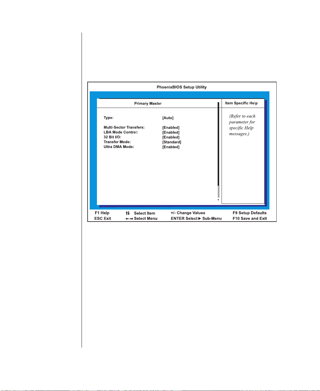
Hard Disk Drive Setup Screen
Primary Ma ster,
Primary Slave, Secondary Master,
Secondary Slave
CYLINDERS, HEADS, SECTORS
MAXIMUM
CAPACITY
The hard disk driv e setup screen appear s whene ver t he
or
the main menu screen.
fields are selected from
70 Gateway ALR 8200R User’s Guide
Figur e 36: Example Har d Disk Dri ve Setup Scr een
•
Type offers the following options:
1 to 39
–
–
–
–
- Selecting this options brings up one of a set of previously
defined drive types and sizes. These values only apply to older
drives, generally less than 200-MB in size.
User
- Selecting this option brings up a sub-menu where you can
enter the
of the drive you are configuring. These values are
generally av ailable from the documentation for the drive or the
drive label it self.
Auto
- Selecting this option automatically configures the drive
based on information from the drive itself.
CD-ROM
- Select this option if the driv e is a CD-R O M.
and
Page 81

– IDE Remova bl e - Select this option of the drive is a removable
DISABLED, STANDARD, 2 SECTORS, 4 SECTORS, 8 SECTOR S,
16 SECTORS
ENABLED
DISABLED
ENABLED
DISABLED
STANDARD, FAST PIO 1, FAST PIO 2, FAST PIO 3,
FAST PIO 4
STANDARD, FAST DMA A, FAST DMA B
FAST
DMA F
ENABLED
DISABLED
disk drive.
– AT API Removable - Select this option if the drive i s an AT API
remov able disk dri ve.
–
“ Auto” h as been unable t o supply the driv e type or
None -
select “None” to disabl e any dri ve i nstalled.
•
Multi-Sector T r ansfers:
enabling this option al lo ws multiple
sector data transfers on compatib le dri ves. The options are
.
•
LBA Mode Control:
enabling this option causes Lo gical Block
Addressing to be used in place of Cylinders, Heads and Sectors.
The options are
•
32 Bit I/O:
and
enabling this option all ows 3 2-bit communication
.
between the proc essor and the IDE controller. The options are
•
Transfer Mode:
and
.
selects the method for mo ving data to and f rom
the drive . The options liste d are those supported by t he driv e and
the platform; either
and
; or
, and
.
•
Ultra DMA Mode:
enabling this option al lo ws a faster data
transfer rate with compatib le driv es. The options are
.
and
and
Using the BIOS Setup Utility 71
Page 82

Advanced Menu Screen
Yes
Yes
No
The advanced menu scre en appears allo ws y ou to access a lar ge number of
advanced features. Man y of thes e features can cause t he system to
malfunction if set incorrectly. Do not change these settings unless y ou must.
72 Gateway ALR 8200R User’s Guide
Figur e 37: Advanc ed Menu Scr een
•
Plug and Play O/S: specifies whether the operatin g system is
compatible with Plug and Pla y. The options are
•
Reset Configuration Data: selecting
clear its configuration data and automatically configure all PnP
devices at bootup. Sel ecting
existing configuration information.
•
Use Multiprocessor Specification: this field configures the
multiprocessor specification for compatibility reasons.
Specification 1.4 allows extended bus definitions and is required to
permit a secondary PCI bus to work without a brid ge.
causes the system to use the
causes the system to
and No.
Page 83

Large Disk Access Mode: opt ions include
DOS
Other
DOS
Other
ECC Config
Disabled, EC, ECC,
ECC Scrub.
Enabled
Disabled
Enabled
Disabled
Enabled
Disabled
•
and
if you are using DOS or one of t he DOS-based operating
systems. Select
if you are using another ope rating system
such as UNIX. A large disk is considered one that has more than
1024 cylinders, 16 heads or 63 tracks per sector .
Resource Configuration opens the Resource Configuration
•
screen. Details of this screen are pro vided in th e follo wing section,
“Resource Configuration Screen” on page 74.
Peripher al Configuration opens the P eripheral Configuration
•
screen. Details of this screen are pro vided in th e follo wing section,
“Peripher al Configuration Screen” on page 77.
Keyboar d F eatur es opens th e Ke yboard Configuration screen.
•
Details of this screen are pr o vided in the section “K e yboard
Featu res Screen” on page 79.
Cache Memory opens the Cache Memory Configuration screen.
•
Details of this screen are pr o vided in the section “Cach e Memory
Screen” on page 80.
Advanc ed Chipset Control opens the adv anced chipse t control
•
screen which contains a s ingle field. The field is
allows y ou to set the e xtent of error checking and correction that
the system uses. The options for th is field are
. Select
, which
and
Embedded PCI SCSI: Channel A enabling turns on channel A
•
of the optional integrated SCSI adapt er . The Scan Fi rst option is set
if booting from a hard disk and the Scan Last option is selecte d if
booting from a CD-ROM. The options are
Embedded PCI SCSI: Channel B enabling turns on channel B of
•
and
the optional integrated SCSI adapter. The Scan First option is set if
booting from a hard disk and the Scan Last o ption is selected if
booting from a CD-ROM. The options are
Embedded PCI NIC: enabling turns on the optional inte grated
•
Network Inter face Connection. The options are
and
and
.
SHM Address: defines the System Hardware Manager ( SHM)
•
address. The options are 1 through 7 (Note: alw ays 1 in stand-alo ne
configurations).
.
.
Using the BIOS Setup Utility 73
Page 84

Resource Configuration Screen
Resource Configuration
This screen appears whene ver
advanced menu screen.
is selected off of the
74 Gateway ALR 8200R User’s Guide
Figur e 38: Resour ce Configur ation Scr een
•
Memory Reserv ation: opens the Memory Reservation screen.
This screen allo ws the user to rese rve blocks of upper memory for
use by leg acy ISA de vices. Details o f this screen are provided in
the section “Memory Reservation Screen” on page 75.
•
IRQ Reservation: opens the IRQ Rese rvation screen. This s creen
allows the user to reserve IRQs for use b y legac y ISA de vices.
Details of this screen are pr o vided in the section “I RQ Reservation
Screen” on page 76.
Page 85

Memory Reservation Screen
Memory Reservation
Available
Reserved
This screen appears whene ver
is selected from the
resource configuration screen. It allows you to reserve a bl ock of memory
for ISA devices.
Figur e 39: Memory Rese rvation Scr een
•
XXXX - XXXX: the specified area of upper memory may be
reserved for use by le gacy I SA devic es. Options are
.
and
Using the BIOS Setup Utility 75
Page 86
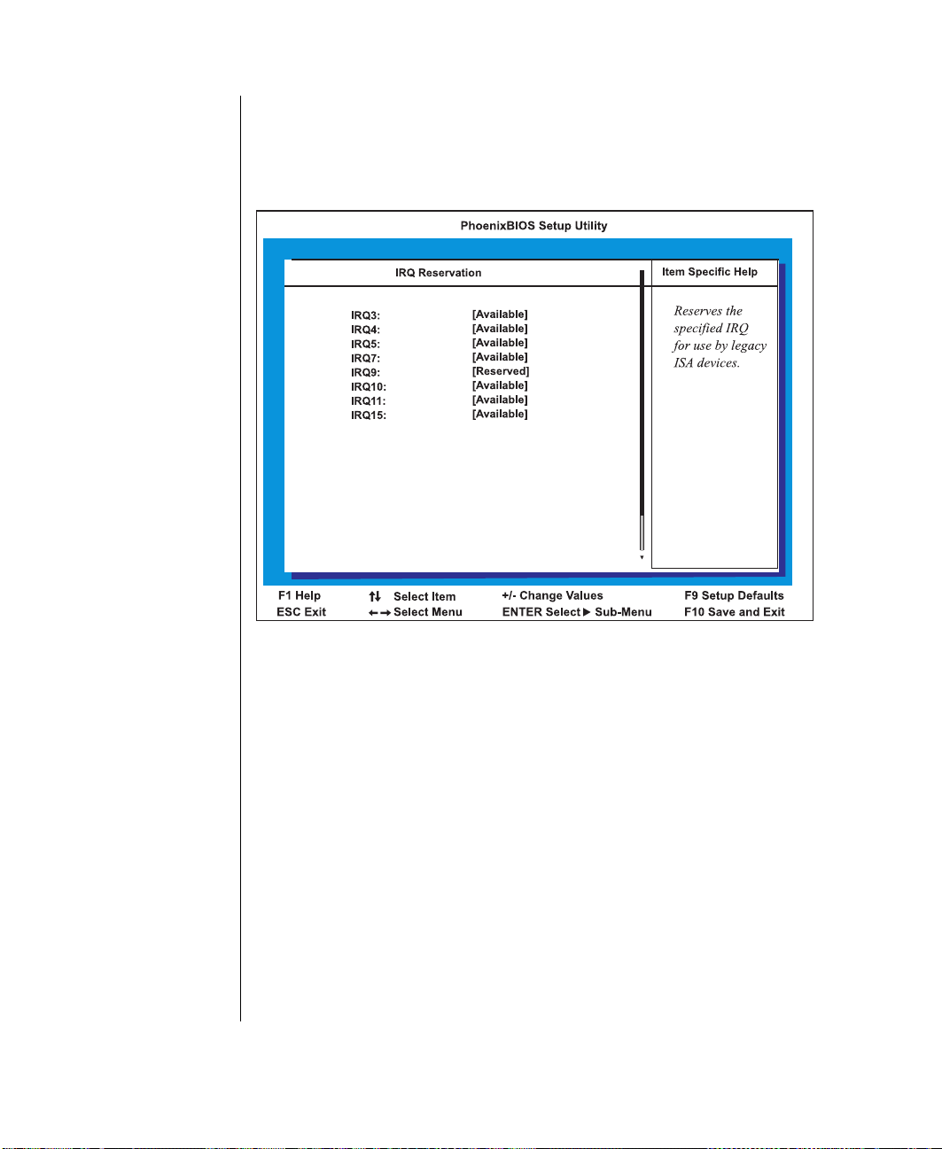
IRQ Reservation Screen
IRQ Reservation
Available
Reserved
This screen appears whene ver you sele ct
from the advanced
menu screen. It allo ws you to manual ly reserve IRQs for s pecific devices.
Figur e 40: IRQ Reservation Scree n
76 Gateway ALR 8200R User’s Guide
•
IRQx: the specified IRQ may be reserved for use by legac y ISA
devices. Options are
and
.
Page 87

P eripheral Configuration Screen
Enabled, Disabled
Auto
Enabled, Disabled
Auto
This screen allo ws you to configure the system peripherals.
Figur e 41: Peripheral Configur ation Scr een
•
Serial P ort A: options include
Base I/O Address:
–
Serial Port A. Using the “+” or “-” key displays t he optional
addresses available.
Interrupt:
–
Port A. Using the “+” or “-” key displays the opti onal addresses
available.
•
Serial P ort B: options include
Base I/O Address:
–
Serial Port B. Using the “+” or “-” key displa ys the optional
addresses available.
Interrupt:
–
Port B. Using the “+” or “-” key displays the optional addresses
available.
displays th e current interrupt for integrated Serial
displays th e current interrupt for integrated Serial
and
displays the base I/O address for integrated
and
displays the base I/O address for integrated
.
.
Using the BIOS Setup Utility 77
Page 88

Parallel P ort: options incl ude
ENABLED, Disabled
Auto
ECP
Bi-directional
Output only
Enable
Disable
Primary
Secondary
•
Mode:
–
–
–
–
Floppy Disk Contr oller: controls the inte grate diskette controll er .
•
Options include
–
displays the current parallel port mode. Options include
(Extended Capabilities Port),
Base I/O Addre ss:
Parallel Port. Using the “+” or “-” key displays the optional
addresses available.
Interrupt:
Port. Using the “+” or “-” ke y displa ys the opt ional addresses
available.
DMA Channel:
Parallel Port. Using the “+” or “-” key displays the optional
channels available.
Base I/O Addres s:
displays the current interrupt for the integrated Parallel
displays the base I/O address for the integrated
displays the current DMA channel used by the
and
options include
.
and
and
or
.
.
.
78 Gateway ALR 8200R User’s Guide
Page 89
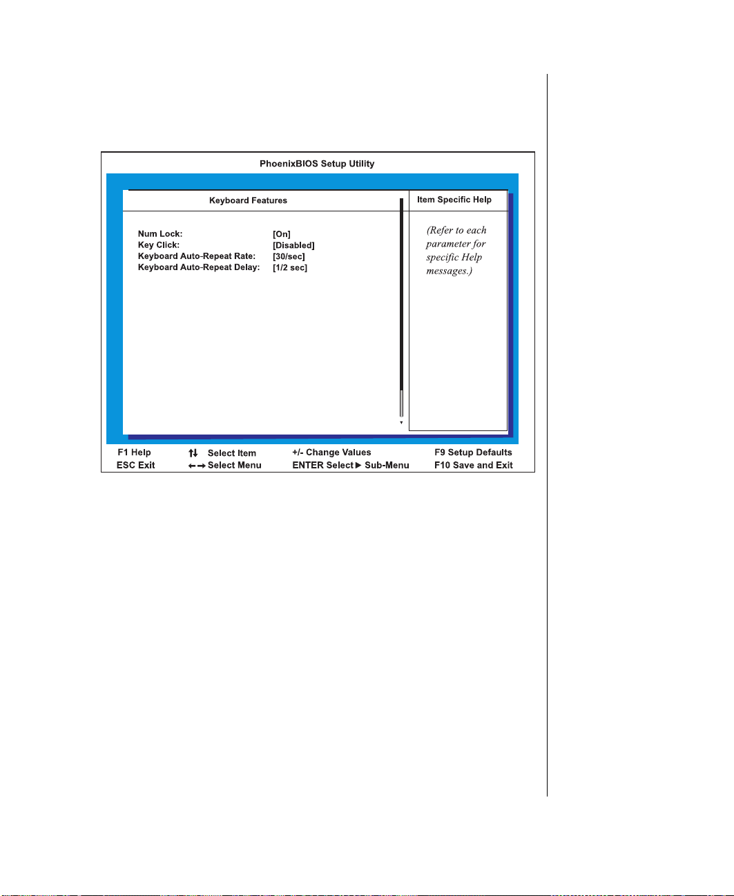
Ke yboard Features Screen
Auto, On
Off
Enable
Disable
2/sec, 6/sec,
10/sec, 13.3/sec, 18.5/sec, 21.8/sec, 26.7/sec
30/sec
1/2 sec, 3/4 sec
1sec
This screen allo ws you to configure the features of y our ke yboard.
Figur e 42: K eybo ar d F eat ures Scr een
•
Num Lock: options include
state of the
•
Key Click: options are
NUMLOCK
audible click w hen each ke y is pressed.
•
Keyboard Auto-Repeat Rate: determines the rate at which a
character repeats if a ke y is held do wn. Options are
•
Keyboar d A uto-Repeat Delay: determines the amount of delay
before a pressed key repeats. Options are
key .
and
and
. Sets the pow er -on
. Enable causes an
, and
.
, and
.
Using the BIOS Setup Utility 79
Page 90

Cache Memory Screen
Enable
Disable
Uncached
Write Protect
UNCACHED
Write Protect
Write Back, Write Through
Uncached
Write Back, Write Through
Uncached
This screen allo ws you to configure various aspe cts of the syste m cache
memory.
80 Gateway ALR 8200R User’s Guide
Figur e 43: Cac he Memory Scr een
•
Memory Cache: options include
or
. Normally used
to troubleshoot speed- related prob lems.
•
Cache System BIOS Area: controls the cachi ng of the system
BIOS area. Options are
•
Cache Video BIOS Ar ea: controls the caching of the video BIOS
area. Options are
•
Cache Base 0-512K: controls caching of the first 512K of base
or
or
memory . Options are
•
Cache Base 512K-640K: controls caching of the 512K through
.
.
or
640K area of base memory . Options are
.
.
or
Page 91
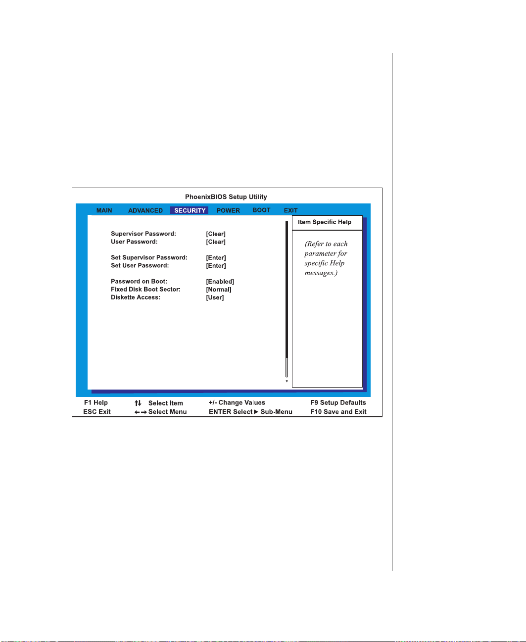
Cache Extended Memory Area: c ontrols caching of the s ystem
Enabled
Disabled
Enabled
Disabled
Clear
Set
Clear
Set
•
memory above 1 MB . Options are
Cache segments (for e xample, C800 - CBFF): controls caching
•
of specified segments of memory. Options are
or
Security Menu Screen
This screen allo ws you to se t system security characteristics.
.
or
.
Figur e 44: Securi ty Menu Scr een
Supervisor Pas swor d: displa ys status of administrati ve pa ssw ord.
•
Options are
been established).
User Passw ord: dis plays st atus of user pass wor d. Options are
•
(no passw ord entered) and
(no passw ord entered) a nd
(a passw ord has been est ablished).
(a passw ord has
Using the BIOS Setup Utility 81
Page 92

Set Supervisor P assw ord opens t he supervisor passw ord menu. In
Normal
Write
Protect,
Supervisor
User
•
this box, the supervisor can enter and verify the p assw ord used t o
control access to the setup uti lity. If the supervisor passwor d has
already been set, the supervisor must enter t he current passw ord
before being able to e nter and verif y the new pass w ord.
Set User Pass wor d sho ws the user pas sw ord menu. In this bo x,
•
you can enter and v erify the pass w ord used to control access to the
system at boot. If the user pass w ord has already been se t, you must
enter the current passw ord before y ou are ab le to enter and v erify
the new passw ord.
Passw ord on Boot: w hen this option i s enabled, the system
•
prompts the user for a pass w ord before booting t he system.
Fixed Disk Boot Sector: options for this field are
•
which protects the boot sector from viruses.
Diskette Access: controls ac cess to the disket te driv e. Options
•
include
supervisor) and
(diskette dri ve is acce ssible onl y to t he
(diskette dri ve is access ible to the user).
and
82 Gateway ALR 8200R User’s Guide
Page 93

P ower Men u Screen
Enabled
Disabled
Enabled
Disabled
This screen allo ws you to se t the character istics of the syst em pow er
management features.
Figur e 45: Power Menu Scr een
•
Po w er Sa vi ngs: opens a menu in w hich you can e nable t he po w er
saving featu res of the system.
•
Standby T imer: opens a menu in whi ch you can select the amount
of time before the system enters i ts lo w-po w er state.
•
Auto Suspend T imeout: opens a menu in w hich you can s elect
the number of PCI clock cycles within w hich a PCI car d must be
guaranteed access to the PCI bus.
•
Device (specified) Monitoring: options are
When enabled , a ctivit y on the de vice specified will keep the
system aw ake.
•
Wake on Embedded LAN: The options are
When enabled the system will w ake from power management
mode when it recei ves a packet o ver the inte grated LAN circuit.
and
and
.
.
Using the BIOS Setup Utility 83
Page 94

Boot Menu Screen
Diskette Drive, Hard Drive, Removable
Devices, ATAPI CD-ROM Drive,
Network Boot
Diskette Drive, Hard Drive,
Removable Devices, ATAPI CD-ROM Drive,
Network Boot
Diskette Drive, Hard Driv e,
Removable Devices, ATAPI CD-ROM Drive,
Network Boot
Diskette Drive, Hard Driv e,
Removable Devices, ATAPI CD-ROM Drive,
Network Boot
This screen allo ws you to se t the order in w hich the system will seek boot
data.
84 Gateway ALR 8200R User’s Guide
Figur e 46: Boot Menu Scr een
•
First Boot Device: de signates the de vice that the sys tem polls first
upon boot up. Options include
and
•
Second Boot Device: designates the device that the system polls
.
second upon boot up. Options include
and
•
Third Boot Device: designates the device tha t the system polls
.
third upon boot up. Options include
and
•
F ourth Boot Device: designates t he device t hat the system polls
.
fourth upon boot up. Options include
and
.
Page 95

Fifth Boot Device: designates the de vice that the system polls fifth
Diskette Drive, HARD Drive, Removable
Devices, ATAPI CD-ROM Drive,
Network Boot
•
upon boot up. Options include
and
Hard Drive: displays a list of a v ailable har d driv es. The system
•
.
attempts to boot to the operating system from the first hard drive
on this list. If no operating s ystem is found , the s ystem tries the
next driv e listed until an ope rating system is found. Use the up and
down arro ws to select a de vice, then pre ss (+) or (-) to mo v e it up
or down the list.
Remov able Device s: displays a list of a vailab le remo vab le devices.
•
The system assigns dri ve letters t o these devi ces in the order
display ed. To change the sequence and drive let ter of a de vice, use
the up and down arro ws to select a de vice, then pr ess (+) or (-) to
mov e it up or do wn the list .
Using the BIOS Setup Utility 85
Page 96

Exit Menu Screen
This screen allo ws you to e xit the Setup pro gram or to sa ve any changes you
have made t o the BIOS settings.
Figur e 47: Exit Menu Scr een
86 Gateway ALR 8200R User’s Guide
•
Exit Sa ving Changes: exits t he BIOS Setup and sa v es the changes
you ha ve entered in the CMOS. The ne xt time you boot the system,
the BIOS configures your system using these settings.
•
Exit Discarding Changes: exits the BIOS Setup an d discards the
settings you ha ve ent ered. The next time y ou boot the syst em, the
BIOS configures your system using the old settings.
•
Load Setup Defaults: displays the s etup defaults in cases w here
the settings hav e been corrupted or incorrectly modified. Press
to resume the boot, or
default values alrea dy loaded into the menus.
•
Discard Changes: restores the CMOS se ttings pre viously e ntered
(not the default value s) and discards the change s entered in the
current session, without exiting the BIOS Setup.
•
Sav e Changes: sa ves the changes you ha v e made during the
current session, without exiting Setup.
F
to run the BIOS Setup with the ROM
2
F
1
Page 97

Updating the BIOS
Update Flash Memory From a File
Update System BIOS
Flash memory simplifies distributing BIOS upgrades. If you need a new
version of BIOS, you ca n downl oad the BIOS update from the Technical
Support web site and instal l the new v ersion fro m a disk.
T o update the BIOS
1.
Enter BIOS Setup by pressing
2.
Write down the settings for each of the parameters. (At the end of the
F
when prompted during startup.
1
BIOS update process, reset the parameters to the correct v alues.)
3.
Exit the BIOS Setup program.
4.
Download the correct BIOS file from the T echnic al Support web site .
Directions are pro vided on the w ebsi te.
5.
Uncompress the contents of the BIOS file you downloaded a nd copy
the contents onto a bootab le disk.
6.
Place the bootable dis k containing the BIOS files into driv e A, then
restart the system with the disk in the dri ve. The BIOS Setup pr ogram
starts.
Press
Select
Select
Press
NTER
E
to go to the Main menu.
and press
AB
T
to select the file name, then press
and press
NTER
E
.
E
E
NTER
NTER
.
.
7.
8.
9.
10.
The system warns you that BIOS is about to be changed.
11.
12.
NTER
E
Press
Once the BIOS files have been loaded , remo v e the disk from dri ve A,
then press
13.
As the system starts up, verify that y ou ha ve loaded the correct BIOS
version.
.
NTER
E
when prompted to restart the system.
Updating the BIOS 87
Page 98

Enter BIOS Setup by pressing
14.
in BIOS Setup, press
F
and then re-enter the val ues you wrote do wn at
5
F
when prompted during startup. Once
1
the beginning of this pro cess.
F
If you do not set the CMOS v alues back to defaults using t he
key or
5
the correct values from y our earlier configuration, the system may
function erratically.
You may encount er a CMOS checksum error or other problem aft er the
system restarts. If so, try turning the system off and then resta rting. CMOS
checksum errors require that you enter BIOS Setup, check your settin gs,
save y our settings , and exit setup.
88 Gateway ALR 8200R User’s Guide
Page 99

Chapter 5:
Maintaining and Cleaning Your System
Contents
Maintaining Your System..................................... 90
Maintaining your Hard Drive......................... 90
Cleaning The System............................................. 93
Cleaning the Mouse........................................ 93
Cleaning the Keyboard................................... 94
Cleaning the Monitor Screen......................... 94
Cleaning the Monitor Case ............................ 94
Page 100

Maintaining Your System
Tools
Properties
Maintaining your Hard Drive
Hard drives need r egular maintenance because running the sof tware di vides
files, creates spaces between data, and otherwise decreases the hard dri ve ’s
performance. Windo ws 95 and W indo ws NT pro vide mainte nance tools
that help prevent hard dri ve prob lems. The tw o most important tools for
hard driv e maintenance are the pro grams ScanDisk and Disk Defragmenter .
(Windo ws NT does not incl ude Disk Defragmenter .)
Using ScanDisk
ScanDisk is a program that lets y ou check your hard dis k for damaged areas
and then repair them. We suggest that you scan your hard dri v e at least onc e
a week to once a month, depe nding on ho w often and ho w much you use
your computer .
T o St art ScanDisk
1.
In Windo ws 95, Click on the
then
Accessories
, then
System T ools
button. Then click on
Start
, and then
Programs
ScanDisk
,
.
90 Gateway ALR 8200R User’s Guide
The ScanDisk window opens.
In Windo ws NT, Scandisk is accessed through the
drive’s
2.
In the ScanDisk windo w, click on the drive y ou want to sca n.
3.
If you onl y want to chec k your files and folders for errors, select the
Standard
errors, select the
Because the Thorough option takes more time th an the Standard
option, we recommend y ou normally use the St andard option and do a
Thorough check at least once a month.
4.
If you selected
ScanDisk uses when it c hecks files and folders, click on the
sheet.
option button. If you w ant to do a more thorough scan for
Thorough
Standard
option.
and you w ant to change the setti ngs
tab of the
 Loading...