

Page 1

Gateway
ALR 7200R
User’s Guide
Supplement
Part #8503437 A MAN SYS US 7200R USR G DE R1 7/98
In our effort to use nature’s resources efficiently and wisely, we print all manuals on recycled papers that meet the
minimum requirements established by the Federal EPA in its guidelines for recycled paper products.
Page 2

Notices
Copyright © 1998 Gateway 2000, Inc.
All Rights Reserved
610 Gateway Drive
N. Sioux City, SD 57049 USA
All Rights Reserved
This publication is protected by copyright and all rights are reserved. No part of it may be reproduced
or transmitted by any means or in any form, without prior consent in writing from Gateway 2000.
The information in this manual has been carefully checked and is believed to be accurate. However,
changes are ma de pe rio dic ally. These changes are incor por ate d in new er pu bli cati on ed iti ons.
Gateway 2000 may improve and/or change products described in this publication at any time. Due to
continuing system improvements, Gateway 2000 is not responsible for inaccurate information which
may appear in this manual. For the latest product updates, consult the Gateway 2000 web site at
www.gateway .com. In no event will Gateway 2000 be liable for direct, indirect, special, exemplary ,
incidental, or consequential damages resulting from any defect or omission in this manual, even if
advised of the possibility of such damages.
In the interest of continued product development, Gateway 2000 reserves the right to make
improvements in this manual and the products it describes at any time, without notices or obligation.
Trademark Acknowledgments
AnyKey, black-and-white spot design, ColorBook, CrystalScan, Destination, EZ Pad, EZ Point, Field
Mouse, Gateway 2000, HandBook, Liberty, TelePath, Vivitron, stylized “G” design, and “You’ve got a
friend in t h e bu si ne ss ” s log a n ar e r eg is t er ed t rad e ma rk s and “All the big trend s s t ar t in So u th D a ko ta ”
slogan, GATEWAY, and Gateway Solo are trademarks of Gateway 2000, Inc. Intel, Intel Inside logo,
and Pentium are registered trademarks and MMX is a trademark of Intel Corporation. Microsoft, MS,
MS-DOS, and Windows are trademarks or registered trademarks of Microsoft Corporation. All other
product names mentioned herein are used for identification purposes only, and may be the trademarks
or registered trademarks of their respective companies.
Copyright © 1998 Advanced Logic Research, Inc. (ALR)
All Rights Reserved
9401 Jeronimo
Irvine, CA 92618 USA
All Rights Reserved
This publication is protected by copyright and all rights are reserved. No part of it may be reproduced
or transmitted by any means or in any form, without prior consent in writing from ALR.
The information in this manual has been carefully checked and is believed to be accurate. However,
changes are ma de pe rio dic ally. These changes are incor por ate d in new er pu bli cati on ed iti ons. ALR
may improve and/or change products described in this publication at any time. Due to continuing
system improvements, ALR is not responsible for inaccurate information which may appear in this
manual. For the latest product updates, consult the ALR web site at www.al r.com. In no event will ALR
be liable for direct, indirect, special, exemplary, incidental, or consequential damages resulting from
any defect or omission in this manual, even if advised of the possibility of such damages.
In the interest of continued product development, ALR reserves the right to make improvements in this
manual and the products it describes at any time, without notices or obligation.
Trademark Acknowledgments
ALR is a registered trademark of Advanced Logic Research, Inc. All other product names mentioned
herein are used for identification purposes only, and may be the trademarks or registered trademarks
of their respective companies.
ii
Page 3

Contents
Preface ................ .............. .............. .......... .............. .............. ....v
About This Guide................................................................................... vi
Conventions Used in this Guide.......................................................... vii
Chapter 1: Introduction ........................ ..... ......... .......... ......... ... 1
Introduction.............................................................................................. 2
Installation Requirements................................................................ 2
Chapter 2: Converting from Mini-Tower to Rack-Mount ......... 3
Introduction.............................................................................................. 4
Remove Existing Panels .................................................................. 4
Install the Rack-Mount Panels......................................................... 6
Chapter 3: Installation ........................................ .......... ......... ...7
Installing the System Drawer.................................................................. 8
Installing the Mounting Rails........................................................... 8
Mounting the System Drawer........................................................ 10
Connecting the System Drawer............................................................ 13
Connecting Peripherals.................................................................. 13
Connecting Multiple System Drawers.......................................... 14
Connecting the Power.................................................................... 15
Powering Up the System....................................................................... 16
First Time Power Up...................................................................... 16
Normal Power Up .......................................................................... 16
Shutting Down the System.................................................................... 17
Completing the Installation................................................................... 18
Installing a Cable Retractor............................................................ 18
Dressing the Cables........................................................................ 18
Securing the System...................................................................... 19
Optional Equipment.............................................................................. 20
Chapter 4: Troublesho oting .................................... ......... ......21
Introduction............................................................................................ 22
Important Safety Instructions................................................................ 23
Computer Virus Notice......................................................................... 25
iii
Page 4

What is a Virus............................................................................... 25
Types of Viruses............................................................................ 25
Virus Contamination...................................................................... 25
Protecting Your System................................................................. 26
Virus Prevention............................................................................ 26
Troubleshooting Checklist ................................................................... 28
Verifying Your Configuration....................................................... 28
Troubleshooting Guidelines.......................................................... 28
CD-ROM Problems.............................................................................. 29
Hard Disk Problems.............................................................................. 30
Memory/Processor Problems............................................................... 31
Modem Problems.................................................................................. 32
Peripheral/Adapter Problems............................................................... 33
Printer Problems.................................................................................... 35
System Problems................................................................................... 36
Video Problems..................................................................................... 38
Error Messages...................................................................................... 40
Appendix A: Regulatory Compliance Statements .................45
FCC Notice............................................................................................ 46
Industry Canada Notice........................................................................ 47
CE Notice.............................................................................................. 47
VCCI Notice ......................................................................................... 48
Australia/New Zealand Notice............................................................. 48
Index ....................................................................................... 49
iv Gateway ALR 7200R User’s Guide Supplement
Page 5

Preface
Contents
About This Guide ...................................................vi
Conventions Used in this Guide............................vii
Page 6

About This Guide
The purpose of this User’s Guide Supplement is to help you get your system
draw er installed and running. This guide pro vides step-b y-step setup an d
operating instructions, along with detail ed illustrations t hroughout the
document. Belo w is a summary of the sections to fol lo w:
Chapter 1: Introduction e xplains installation r equirements for y our ALR
7200R.
Chapter 2: Conv erting from Mini-Tower t o Rack-Mount pro vid es step-b ystep procedures detailing ho w to con vert the ALR 7200 mini-to w er cha ssis
to a rack-mountable syst em dra w er .
Chapter 3: Installation explains ho w to inst all the rack-mountab le dra w er
into a cabinet.
Chapter 4: T roub leshooting pro vide s reference ma terial on
troubleshooting y our system.
Appendix A: Regulatory Compliance Statements pro vides a listing of
compliance standards that this s ystem meets.
For addi tional information on this system, refer to the ALR 7200 User’s
Guide and Maintaining and T r oubl eshooting the ALR 7200.
We recommend you take time to r ead through the manual bef ore using the
system. If you encounter a prob lem, refer to the h andy troublesho oting
section pro vided.
vi Gateway ALR 7200R User’s Guide Supplement
Page 7
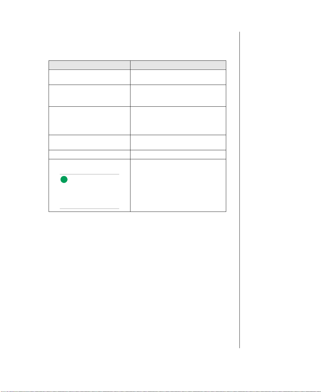
Conventions Used in this Guide
Note:
This is an example of an
important note that may
appear in the manual.
Throughout this booklet, you will see the fol lo wing con ventions :
CONVENTION DESCRIPTION
ENTER
CTRL + ALT + DEL
Setup
System User’s Guide Names of publications and files are
RUN
Sidebars Sidebars denote critical information
A key name corres ponds to a key on
the keyboard.
A plus sign indica tes that the keys on
either side of it must be pressed
simultaneously.
Commands to be entered as well as
messages that appear on your
monitor are printed in bolded “Arial
Narrow” font .
italicized.
Options to select are boldfaced.
such as war nings, important
information, and important notes.
Conventions Used in this Guide vii
Page 8

viii Gateway ALR 7200R User’s Guide Supplement
Page 9

Chapter 1:
Introduction
Contents
Introduction.............................................................. 2
Installation Requirements................................ 2
Page 10

Introduction
Congratulations on your purchase of the ALR 7200R. W ith t he arrival of
your new syst em, you are pr obabl y eager to instal l your syste m and ha ve it
operating.
Installation Requirements
The ALR 7200R system draw er is desi gned for an of fice environment and
allows for floor-le vel entry of all cables through the opening i n the bottom
of the cabinet. No special peripher al cab le entry kits are required. The
cabinet can be installed in a r aised floor en vironme nt as we ll as in a soli d
floor office environment.
Proper planning is necessary to minimize prob lems during setup. When
determining the setup location for the syst em, keep in mind the si ze (height
and width) of stairs, ele vat ors, hall wa ys, and doorw a ys.
Once the cabinet is at its final destination, lo w er the stabilizi ng feet by
turning them clockwise until they make a firm contact with the floor . The
stabilizing feet help pre vent the cabinet from tippin g or rocking w hen the
draw er is e xtended.
If you are install ing sev eral cabinets t ogether, "gang" them together b y
removing th e side panels betw een the c abinets and bolti ng the cabinets
together . Remo ving the in-betw een side panels al lo ws efficient routing of
cables betw een the cabin ets to help maintain a c ommon electrical ground.
A kit designed to facilitate this is a vailab le from th e manufacturer .
If your system came configured as a tow er , pl ease refer to Cha pter 2:
Converting f r om Mini-Tower to Rac k-Mount, for information on con v erting
your system. If con ve rsion is not necessary, you may skip to Chapter 3:
Installation.
2 Gateway ALR 7200R User’s Guide Supplement
Page 11

Chapter 2:
Converting from Mini-Tower to Rack-Mount
Contents
Introduction.............................................................. 4
Remove Existing Panels................................... 4
Install the Rack-Mount Panels......................... 6
Page 12
Introduction
The ALR 7200 minitow er chassis pro vides the capabili ty to easil y con vert
into a fully fun ctional, standard 19" r ack-mountab le dra w er . To accomplish
this, a Rack Conv ersion Kit is a v ailab le. If your syste m came preconfigured for rack installation, you may skip thi s section and proceed to
Chapter 3.
Before proceeding, turn off syst em pow er and disconnect all peri pherals.
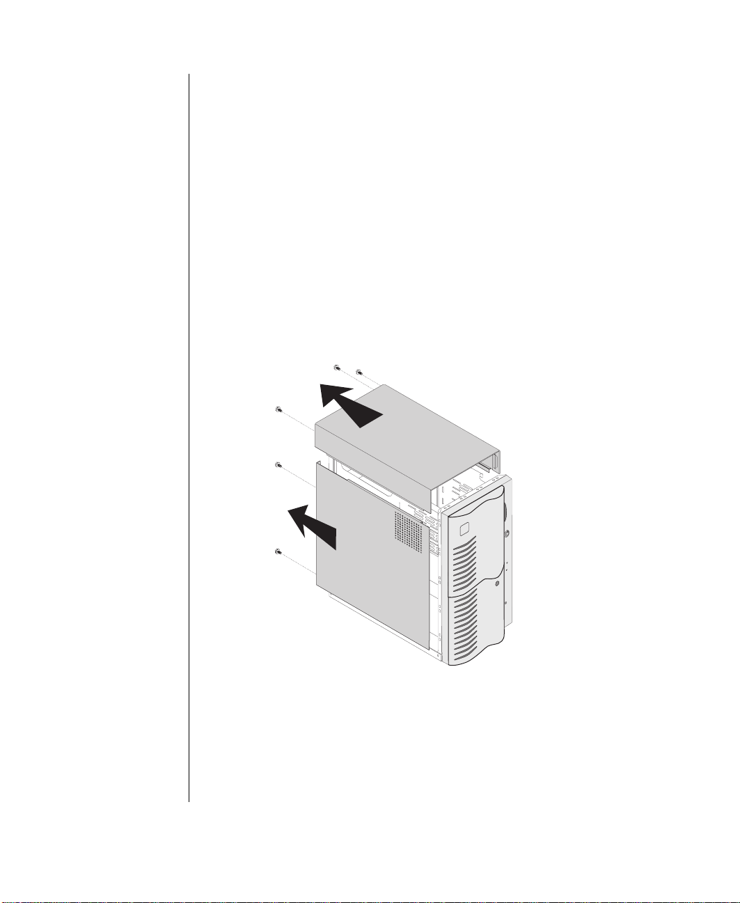
Remove Existing Panels
1. Remove the three scre ws located on the rea r of the system.
2. Slide the top panel back, then pull t he co ver up.
3. Remove the tw o screws l ocated on the rear of t he system, left side.
4. Slide the side panel back, then pull the c o ver of f.
5. From the inside of the cha ssis, remo ve t he tw o scre ws securing the
bezel to the chassis.
4 Gateway ALR 7200R User’s Guide Supplement
Page 13
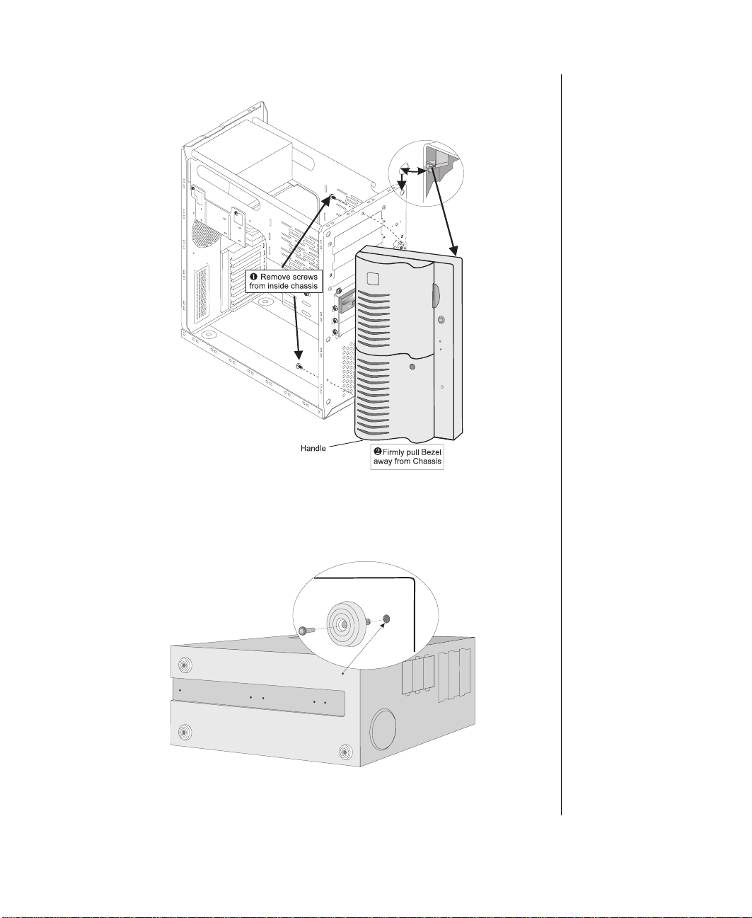
6. Holding onto the bottom handle, firmly pull bezel aw a y from chassis.
7. From the inside of the system, push out the pi n, located in the center of
the plastic foot, with a scre wdri ver. Remov e F eet from t he bottom of
the minitower.
Introduction 5
Page 14
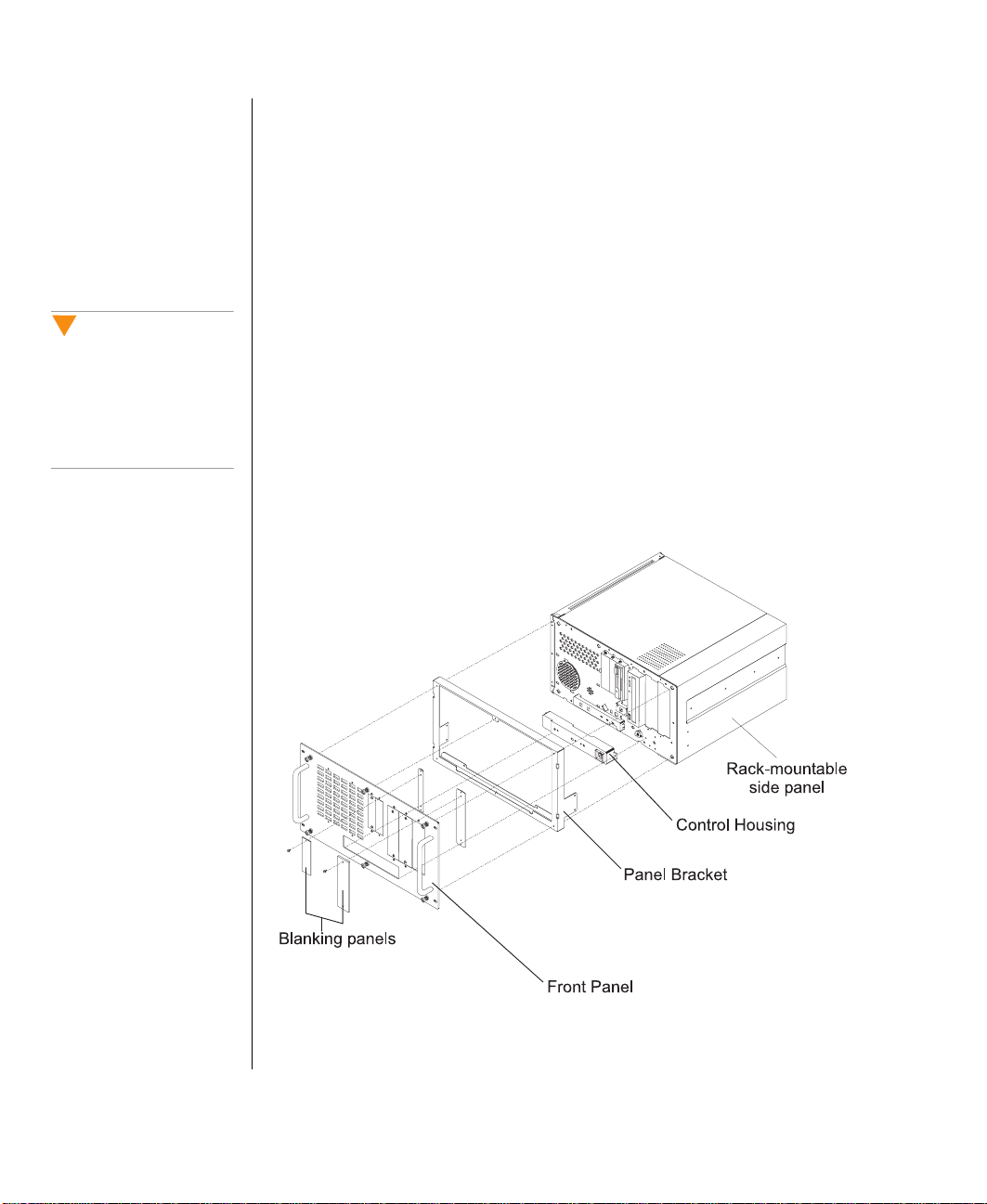
Install the Rack-Mount Panels
Caution!
Keyboard Inhibit Switch
should be turned off or the
connector unplugged from
the system board. See
Figure 1-3 in the ALR 7200
User’s Guide.
1. Install Rack bus module to rear of system. Plug connec tor to system
board.
2. Replace the left side panel using thumb scr ews pr o vided in kit.
3. Replace top panel with a rack-mountab le side panel.
4. Install Control Housing o ve r po w er button.
5. Install the Panel Brack et.
6. Remove blanking panel s, corresponding to the devices being used ,
from Front Panel. If a de vice is not being used , leave the
corresponding blanking panel in place. Plastic snap plugs, used to
cov er scre w holes, may be remo ved and st ored on the top of the panel
bracket.
7. Install the Front P anel.
6 Gateway ALR 7200R User’s Guide Supplement
Page 15

Chapter 3:
Installation
Contents
Installing the System Drawer.................................. 8
Installing the Mounting Rails........................... 8
Mounting the System Drawer........................ 10
Connecting the System Drawer............................ 13
Connecting Peripherals.................................. 13
Connecting Multiple System Drawers.......... 14
Connecting the Power.................................... 15
Powering Up the System....................................... 16
First Time Power Up...................................... 16
Normal Power Up........................................... 16
Shutting Down the System.................................... 17
Completing the Installation................................... 18
Installing a Cable Retractor............................ 18
Dressing the Cables........................................ 18
Securing the System....................................... 19
Optional Equipment.............................................. 20
Page 16
Installing the System Drawer
Note:
Drawer heights are
measured in U’s. Each U is
equivalent to 1.75 inches.
The ALR 7200R is 6U’s
(10.5 inches) high.
Installing the Mounting Rails
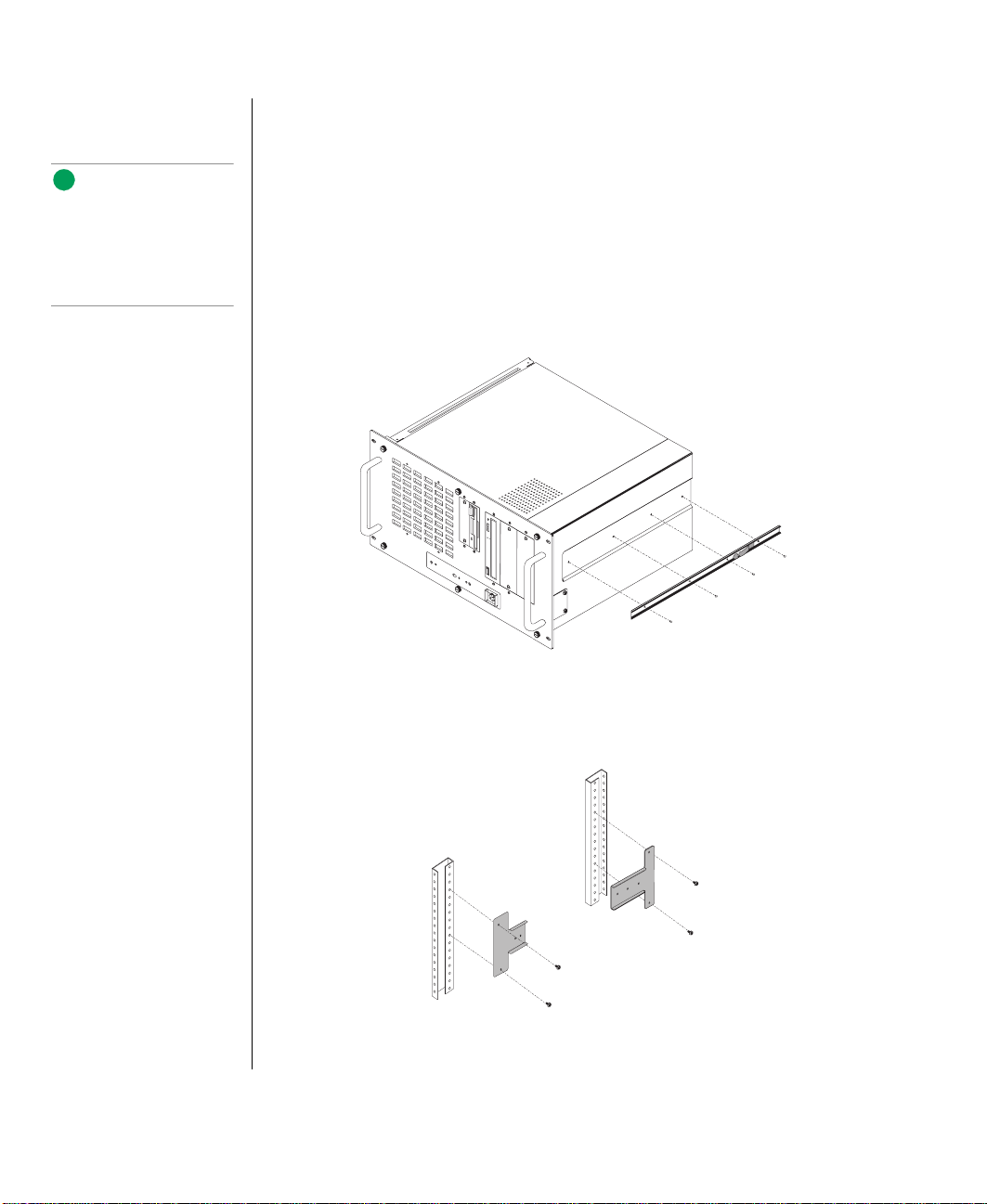
1. Remove the side rails from the mounting rails, b y depressing the
retention clips and sliding them of f.
2. Mount the side rails on the system chass is with the 8 scre ws (4 to each
side) pro vided. The retention cl ips should go to w ard the rear of t he
cabinet.
8 Gateway ALR 7200R User’s Guide Supplement
3. If the mounting rails ha ve not p revi ously been i nstalled , position the
draw er templ ate (P/N 65770050-00) in the ca binet so that the side
matches the corresponding side you wish to install.
Page 17
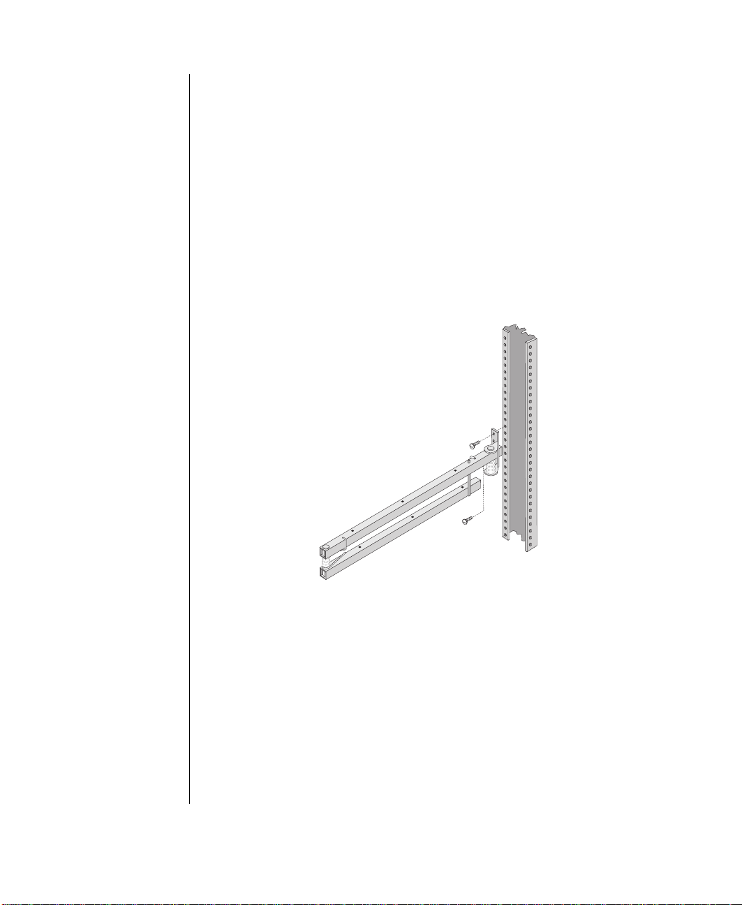
4. Mark the screw hole locat ions onto the vertical mounting strips in t he
cabinet as sho wn on the templat e. The marks will l ocate the mounting
holes of the rail bracke ts and front panel.
5. Attach the front bracket t o the front cabinet v ertical mounting strip
using two scr ews as marked. Attach the rear bracket to t he rear
cabinet vertical mounting strip.
6. Repeat steps 4 and 5 to mount the second set of brackets.
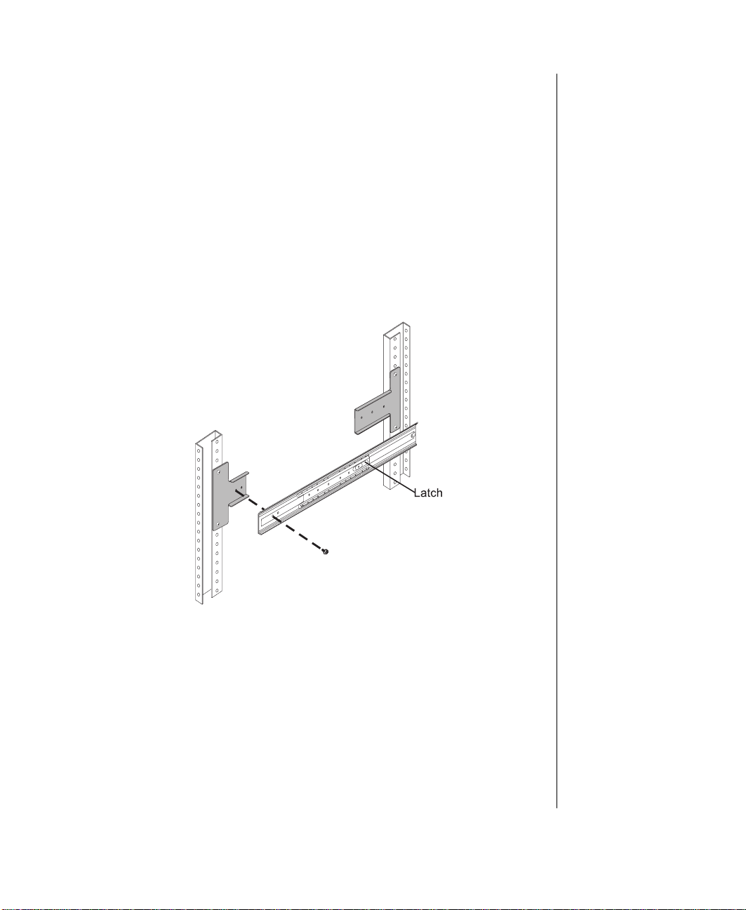
7. T o secure the r ails to the mounting brack ets, begin with the rear of the
rail first. Slide inner rails forward to g ain access to mounting holes . If
the latch locks the rail int o place, release the l atch to allo w the ra ils to
slide freely.
8. Install the mounting scre ws through the r ail into the rear mount ing
bracket.
9. T o secure t he front of the r ail, slide inner rail so th at the opening alig ns
with the mounting holes.
10. Install the mounting scre ws. Verify that the inner rails slide in and out
freely.
Installing the System Drawer 9
Page 18
Mounting the System Drawer
Caution!
The system drawer is
heavy and awkward. To
avoid possible injury or
damage to the system, get
some help when lifting it
into place, aligning the rails
and installing it into the
cabinet.
to mount the system drawer
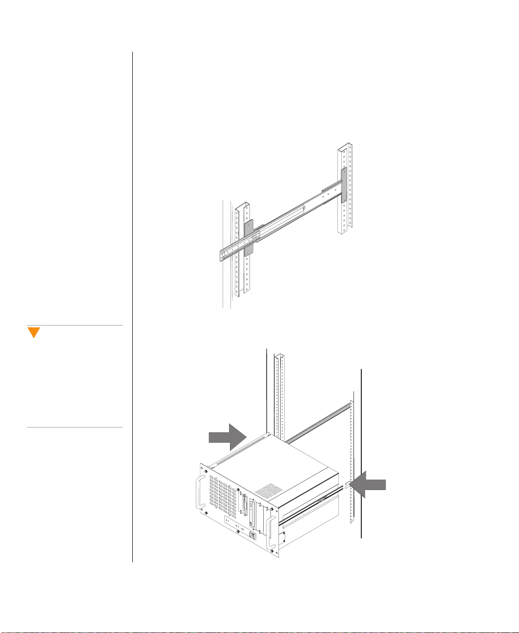
1. Pull forward the inn er rails inside the mounting rails unti l the inner
latch locks the inner rail i n the "out" positi on.
2. Pull the inner slides all th e wa y forw ard.
3. Lift the system dra w er to the same height as the mounting rails and
align the rails on the dra w er with cabin et mounting rails.
10 Gateway ALR 7200R User’s Guide Supplement
Page 19

4. Press the cabinet mounting rails to wards t he center of the cabine t
while inserting the side rai ls on the system dra w er into t he cabinet
mounting rails.
5. Push the system dra wer ev enly into the cabinet until the latches on the
draw er rails lock.
6. Press the latches on both sides of the system dra w er and push the
draw er back un til the front panel touches the vertical mounting rai ls.
The draw er ma y mo ve reluctantly at first. Howe ver , it should mo ve
smoothly, without binding or restrictio n thereafter .
Installing the System Drawer 11
Page 20

When assembled and mounted correctly, the front panel should look l ike
the abov e illustrat ion.
12 Gateway ALR 7200R User’s Guide Supplement
Page 21

Connecting the System Drawer
Connecting Peripherals
1. Po w er of f all dra w ers and de vices in t he cabinet before att aching any
of the system dra w er cable s.
2. Verify that the system dra w er po w er s witch is OFF as w ell.
3. If you plan on setting up the system dra w er to control other dra w ers in
the cabinet, connect exte rnal data cable(s) of their corresponding
controller card(s) to the d evice(s) to be controlled.
4. If daisy-chaining the system dra w er , co nnect a rackbus cab le into one
of its rackbus connectors as w ell as the next dra w er’s rackbus
connector . Up to se ven dra w ers c an be connected this w a y.
5. Connect all I/O device cab les (ke yboard, mouse, video, serial and
parallel) to their respe ctiv e ports on the rear of the syst em dra w er .
Connecting the System Drawer 13
Page 22
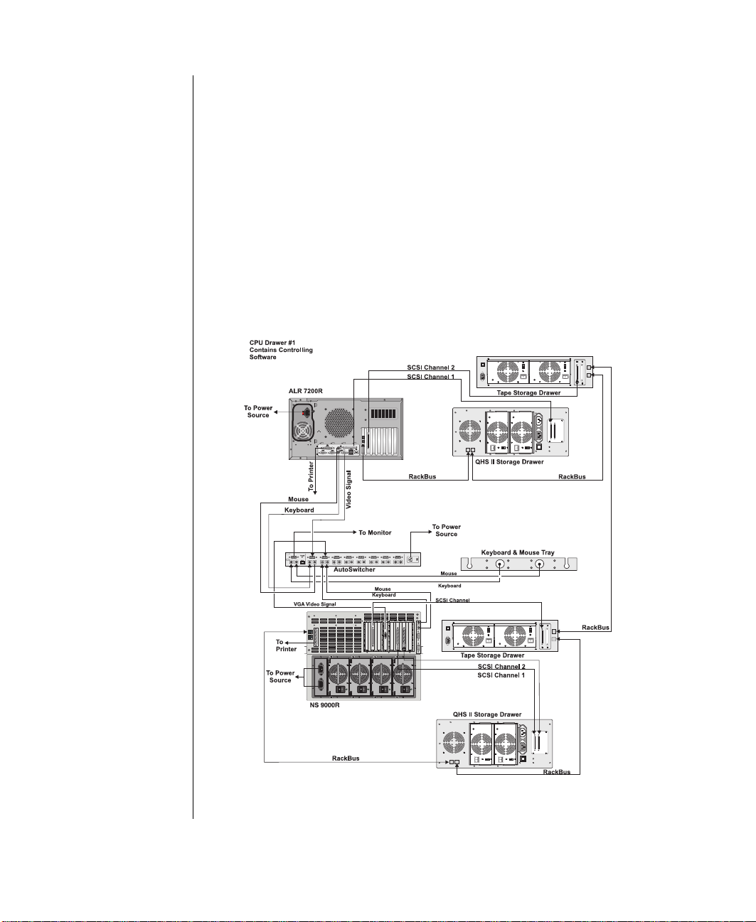
Connecting Multiple System Drawers
Multiple system dra w ers, instal led in a system cabinet, ca n share a single
set of peripherals (monitor , keyboard, and mouse) if a switch bo x, such as
the AutoSwitcher is installed.
The AutoSwitcher gives e xclusi ve cont rol of the monitor as w el l as routes
the keyboard and mouse input s to the currently selected s ystem dra w er .
Installation of the AutoSwitcher is relati vel y simple and covered in detail in
the system cabinet user’s guide.
Connecting multiple system dra w ers requires e xtender ca bles to be pl ugged
into the rear of the system dra w ers and connected to the appropr iate I/O
ports on the rear of the AutoSwitcher . Refer to t he follo wing figure for
connection details.
14 Gateway ALR 7200R User’s Guide Supplement
Page 23

Connecting the Power
It is recommended to ha ve a licensed ele ctrician install a dedi cated 230VAC
line with sufficient amp capacity for the system dra w er to a br eaker bo x or
distribution panel. The po w er cords must be wir ed directl y into the break er
box.
If you choose to use 115VAC, be careful to not o verl oad any plug st rip or
wall outlet. The following guidelines should be observed:
• Only one system dra w er per plug str ip (15 or 20 amps) or w all
outlet (15 or 20 amps). F or mission criti cal applications, pl ug the
system draw ers’ pow er cords into i ndependent po w er sources .
• If a UPS is installed , onl y one CPU dra w er ma y be plugged int o it.
The pow er cords must then be routed through the cabinet’s floor opening
and to the system dra w er . The elect rician will ensure t hat the current
demands will be balanced and that the sys tem maintains a good ground.
Depending on the plug-in configuration, the following de vices ma y share
the same plug strip:
Important!
Because the system drawer
uses a significant amount of
current and can easily
overload the power
circuitry, it must be
connected to the power
source correctly following
the guidelines provided.
Note:
Use only shielded power
cords when connecting the
System drawer.
Plug - In
Configuration
230VAC 15-amp
115VAC 15-amp
Plug
Strip
20-amp
20-amp
Total Supported Devices
• System Draw e r
• QHS Storage Draw er
• T ape Storage Dra w er
Total must not exceed 12 amps.
• System Draw e r
• QHS Storage Draw er
• T ape Storage Dra w er
• Monitor
• AutoSwitcher
Total must not exceed 16 amps.
• System Dra we r only
• System Dra we r with other
peripherals, not to exceed a
total of 16 amps.
Warning!
When connecting other
components to the plug
strip, do not exceed 80% of
the rated capacity of the
plug strip.
Connecting the System Drawer 15
Page 24

Powering Up the System
Note:
Booting each System
drawer separately is not
normally required, but it is
recommended for the first
time power up of your
system to help identify any
power or cabling
configuration problems.
First Time Power Up
1. If using a UPS, turn it on first.
2. Po w er on the mon itor and an y additional de vices connected to t he
system draw er. Listen for audible alarms that might indicate pos sible
pow er prob lems.
3. If multiple system dra w ers and a s witch box a re installed, press the
switch box butto n that corresponds to the System dra w er tha t is being
pow ered up.
4. For t his first time pow er -up, if multiple System dra w ers w ere instal led ,
wait until the first System draw er has boot ed completel y before
pow ering up additi onal System dra w ers.
5. Press the ON/OFF button on the system dra w er . Listen f or audible
alarms that might indicate possible po w er prob lems. Verify that the
pow er indic ator is lit. The monitor s hould displa y the normal P o w er
On Self Test (POST) information, such as counting up memory and
checking the CPU(s), etc. If the monitor does not displa y information
or the System dra w er indicates an error condition, ref er to the
Troub leshooting secti on.
6. Once the system draw er has booted successfull y, you can begin
7. Repeat steps 3 through 6 for each addit ional System dra w er instal led.
Normal Power Up
Po w er on de vices and dra w ers at tached to the system drawer first. When
they ha ve completed their po w er on sequences, po w er on th e system dra w er .
16 Gateway ALR 7200R User’s Guide Supplement
configuring your system draw er to y our requirements b y installing the
operating system of your c hoice.
Page 25

Shutting Down the System
1. Halt, stop, or cancel any act iv e processes or tasks bei ng performed by
the operating system of the system dr a wer being shut do wn.
2. If appropriate, issue a "flush" command to write the content s of an y
caches or buffers t o disk.
3. If appropriate, issue a command to exit or quit the operating system.
4. Press the ON/OFF switch on the syst em dra wer. If the system dra wer
has other dra wers connected to it e xclusi vel y and will remai n off at
length, you ma y want t o pow er down the other draw ers as w ell.
Shutting Down the System 17
Page 26
Completing the Installation
Installing a Cable Retractor
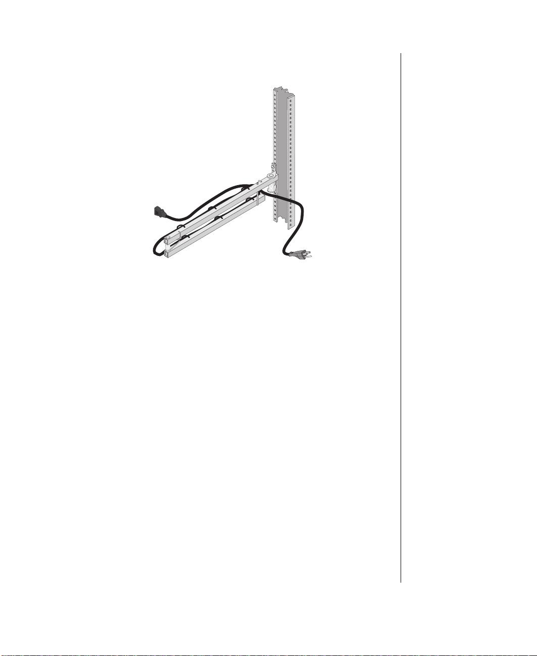
Cable retractors of fer set up advantages in that they r educe strain on t he
draw er cab les and connecto rs as we ll as simplify mai ntenance because the y
keep the cables ne atly out o f the w ay. Install the cable retr actors as follo ws:
1. Position t he cable ret ractor to the rear side of the cabinet so t hat the
mounting holes on both retractor and c abinet are aligned.
2. Using two scre ws, secur e the cab le retractor to th e mounting holes on
the rear of the system dra w er.
Dressing the Cables
1. Route the cable(s) fr om the rear of the system drawer o ver to t he cable
retractor , where it i s mounted on the rear of the dra w er .
2. Secure the cables to t he cable ret ractor with tie str aps. The cab le
retractor is designed with ti e holes wh erein to insert and fasten the tie
straps.
18 Gateway ALR 7200R User’s Guide Supplement
Page 27
3. Leave e nough slack in the cab les to allo w the m to flex w hen the
draw er is pulle d out.
4. Check the cables for ti ght spots wh ile the dra w er is being pull ed
forward and pushed ba ck into place. Check fo r stress points especi ally
at the bends in the cabl e retractor and w here the cab le retract or is
mounted to the vertical mounting rail.
5. Route the cables to the ir destinations and se cure with tie straps a s
required.
6. If necessary , bundle and se cure exces s cable with a tie strap to k eep it
out of the wa y.
Securing the System
1. Close the rear door of the system. Lock if desi red.
2. Push the system dra wer back until its front panel presses agains t the
vertical mounting rails i n the cabinet. Secure the dr a we r with four
screws.
3. Close the front door . Lock if de sired.
Completing the Installation 19
Page 28

Optional Equipment
Caution!
Power the system OFF and
disconnect the power cord
before proceeding.
Installing any component
while the power is ON may
cause permanent damage
to the system.
Achtung!
Schalten Sie das Gerät aus
und entfernen Sie das
Netzteil, bevor Sie
fortfahren. Der Einbau von
Zusatzkomponenten im
laufenden Betrieb kann
gefährlich sein und
bleibende Schäden am
System hinterlassen.
The ALR 7200R Rack-mountable system dra w er ma y be enhanced to meet
your future needs. For detailed instructions on how t o install optional
equipment, please refer to the
complete list of a vail able options for your system, contact y our dealer.
Gateway ALR 7200 User’s Guide. F or a
20 Gateway ALR 7200R User’s Guide Supplement
Page 29

Chapter 4:
T roubleshooting
Contents
Introduction............................................................ 22
Important Safety Instructions................................ 23
Computer Virus Notice......................................... 25
What is a Virus ............................................... 25
Types of Viruses............................................. 25
Virus Contamination...................................... 25
Protecting Your System................................. 26
Virus Prevention............................................. 26
Troubleshooting Checklist.................................... 28
Verifying Your Configuration....................... 28
Troubleshooting Guidelines........................... 28
CD-ROM Problems............................................... 29
Hard Disk Problems.............................................. 30
Memory/Processor Problems................................ 31
Modem Problems .................................................. 32
Peripheral/Adapter Problems................................ 33
Printer Problems.................................................... 35
System Problems................................................... 36
Video Problems..................................................... 38
Error Messages...................................................... 40
Page 30

Introduction
Note:
Do not return any
equipment without
obtaining a Return Material
Authorization (RMA)
number.
If your system does not oper ate correctly, re-read the instructions for the
procedure(s) you ha v e performed and verify that y ou performed the
procedure correctly and completely. If an error occurs in an application,
consult the documentation supplied with the software.
This section identifies solutions to common problems. If the suggestions i n
this chapter do not resolv e your prob lem, call Technical Support.
22 Gateway ALR 7200R User’s Guide Supplement
Page 31

Important Safety Instructions
Observe the follo wing guidelines w hen performing any w ork on you r
system:
1. Foll ow all instructions marked on t his product and in the
documentation.
2. Unplug this product from the w all outlet be fore cleaning. Do not use
liquid or aerosol cleaners. Use a damp cloth for cleaning the exterior
only. Do not attempt to clean interior components.
3. Do not use this product near w ater . Do not spill liquid on or in to the
product.
4. Do not place this product on an unstab le surface.
5. Openings in the system cabinet are pro vided f or ventilat ion. Do not
block or co ver these openings. Do not pl ace this product near or upon
a radiator or heat re gister .
6. Use only the po w er source i ndicated on the po w er suppl y. If you are
not certain about your po w er source, cons ult your res eller or the local
power company .
7. This product is equipped with a 3-wire grounding plug (a plug with a
grounding pin). This plug will only fit into a grounded pow er o utlet.
This is a safety feature. If y ou are unab le to insert the plug into the
outlet, contact your e lectrician to repl ace the outlet.
Warning!
Do not attempt to service
the system yourself except
as explained elsewhere in
the manual. Adjust only
those controls covered in
the instructions.
Opening or removing
covers marked “Do Not
Remove” may expose you
to dangerous voltages or
other risks.
Refer all servicing of those
compartments to qualified
service personnel.
8. Do not walk on the po w er cord or allow anything to rest on it.
9. If you use an extensi on cord with this system, mak e sure the total
ampere ratings on the products plugged into the extens ion cord do not
exceed the extension cor d ampere rating. Also, the tot al ampere
requirements for all products pl ugged into the w all outlet must not
exceed 15 amperes.
10. Never insert objects of an y kind into the syst em ventilation slots.
Important Safety Instructions 23
Page 32

11. Unplug the system from the w all outlet and refer servicing to qualified
Important!
The system power cord
serves as the main
disconnect for the
computer. The wall outl et
must be easily accessible
by the operator.
personnel if:
a. The power cord or plug is damaged.
b. Liquid has been spilled into the s ystem.
c. The system does not operate properly when the oper ating
instructions are follo w ed.
d. The system was dropped or the c abinet is damaged.
e. The system’ s p erformance changes.
24 Gateway ALR 7200R User’s Guide Supplement
Page 33

Computer Virus Notice
What is a Virus
A virus is a program written with malicious int ent for the sole purpose of
creating hav oc in a comput er system. It attaches i tself to ex ecutab le files or
boot sectors, so it can replica te and spread.
Some viruses may onl y cause your syst em to beep or displa y messages or
images on the screen. Other viruses are highl y destructi ve and corrupt or
erase the contents of y our files or disks. T o be safe, ne ve r assume an y virus
is harmless.
T ypes of Viruses
Viruses are identified by ho w the y infect computer syste ms.
• Program viruses infect executab le program files such as .com, .ex e,
.ovl, .drv, .sys, and .bin.
• Macro virus es infect macro files of programs such as w ord
processing and spreadsheet pro grams.
• Boot viruses attach themselves to a boot record, master boot, FAT , or
partition table.
• Multipartite viruses are both program and boot infectors.
Virus Co ntamination
There are many w a ys a virus can spread and infect your syst em. Ho we v er , a
virus is inactive until the infected pr ogram is e xecute d , or a boot r ecord is
read. Thereafter , the virus loads itself into system memory and begi ns to
copy and spread it self.
Disks used in a contaminated system can get infected and , in turn, transfer
the virus when used in another system. A virus can also spread via
programs downl oaded from bulletin boards or the Int ernet. Remember that
viruses cannot appear all by themselv es. They ha v e to be written, then
spread through direct contact with ex ecutabl e pro grams or boot sectors.
Computer Virus Notice 25
Page 34

Protecting Y our System
A w areness is t he key. You need to learn about the existence of viruses, ho w
they spread , and w hat to do to p rotect y our system b y reducing the
likelihood of virus contamination. The follo wing ma y help:
• Obtain an anti-virus program and make i t a habit to scan the
system regularly. These pro grams may be purchased fr om a local
software store or obtained via share w are on the Internet or online
service providers such a s CompuServe, Prodigy, A OL, or
DeltaNet.
• Make backup copies of all files and write-protect the disks.
• Obtain all softwar e from reputab le sources and al w a ys scan ne w
software for an y viruses before instal ling files.
If you suspect y our system has been i nfected, you must find and remove the
viruses immediately using an anti-virus pro gram. Next, reboot y our system
as follo ws: shut the system do wn, then t urn it off for at least 15 seconds
before turning it back on. This is the onl y wa y to ens ure the virus does not
remain in your system RAM.
Virus Prevention
We stand by the integrity of our products. Our staf f takes e very precauti on
to ensure our files are free from viruses. These precautions include the
following:
• We use McAfee VirusScan, a leading ant i-virus software t hat
detects and remo ves o v er 95% of kno wn viruses and pro vides
comprehensive protec tion including local a nd netw ork dri ves, CDROMs, floppies, boot se ctors, and partition tab les. V irusScan also
provides advanced prot ection agains t unkno wn viruses. We
continuously update and use t he most current version of McAfee
VirusScan on all of our pr oducts.
• All master disks are write-prot ected and scanned at leas t twice
before release.
• Sample production disks are periodicall y scanned as a n additional
quality check.
26 Gateway ALR 7200R User’s Guide Supplement
Page 35

• All incoming products such as syst ems to repair , vendor disks,
hard drive s, and trade-sho w units are scanned for viruses.
• All systems are giv en a final test before shipping.
Unfortunately, today’s technology makes the c reation of new er viruses
possible, some of w hich can elud e ev en the best scanners a v ailab le. Hence,
there is no absolute guarantee of virus immunity on any p roduct. If you
think you ha ve recei v ed an infected product from us, please conta ct
T ec hnical Support. Our staf f will assist y ou in correcting the problem.
Computer Virus Notice 27
Page 36

T roubleshooting Checkl ist
Before turning on the system, make sure that:
• The pow er cord is connec ted to the A C po w er -in connector and a n
AC outlet .
• The AC outle t is suppl ying po w er .
• If a pow er s trip is used, it is turned on, and the circuit breaker is se t.
• The voltage selection switch on the system po w er suppl y reflects
the proper voltage.
V erifying Y our Configuration
If your system is not operati ng correctly, the BIOS may contain an in valid
configuration parameter. Enter the BIOS pro gram and check your
configuration settings.
T roubleshooting Guidelines
As you troubleshoot y our system, f ollo w these guidelines:
• Never remo v e the system co ve r while the s ystem is turned on.
• Do not attempt to open the monitor; it i s extremel y dangerous.
Even if the monitor’s power is d isconnected , st ored energ y in the
monitor’s components c an cause a painful or harmful shock.
• If a peripheral such as the k eyboard, mouse, drive, or pri nter does
not appear to w ork, verify that all connections are secure.
• If an error message displays on the scr een, write it do wn, w ord for
word. You may be asked for it wh en calling Technical Support.
• Only qualified personnel should open the system for maintenanc e.
• If you are qualified to maintain the system y ourself, make certain
you are properl y grounded before opening the syste m chassis.
Refer to the Maintaining and T r oub leshooting Guide for more
information on preventi ng electrostatic da mage to the system.
28 Gateway ALR 7200R User’s Guide Supplement
Page 37

CD-ROM Problems
An audio CD produces no sound.
Probable Cause Solution
The CD is loaded
incorrectly.
The speakers are not
connected.
The speaker volume is
turned down.
The speakers may be
muted via the Multimedia
volume control.
The sound card may not
be installed correctly.
The speakers may be
faulty.
The CD-ROM drive is not recog nized by the system.
Probable Cause Solution
The CD is not intende d for
PC use.
The CD is loaded
incorrectly.
The CD is scratched or
dirty.
The CD-ROM driv e needs
to be added as new
hardware.
The secondary IDE de vice
may be disabled.
The CD cables are not
installed correctly.
Make certain the label is facing upward, and then
try again.
Check the speaker cables. Make certain they are
connected properly and securely.
Check the volume control.
From the Accessories menu (Start | Programs |
Accessories), click Multimedia, and then click Volume
Control. Make certai n the volume is turned up.
Open the system, and then re seat the s ound card.
Make certain the cables are connected properly.
Connect a set of headphones to the speaker jack
to test the output. If they work, replace the
speakers.
Make certain the CD is PC-compatible.
Make certain the label is facing upward, and then
try again.
Try cleaning the CD with a lint-free cloth. Check
the CD for scratches.
From the Control Panel window (Start | Settings |
Control Panel), double-click Add New Hardware. Follow
the directions to add the drive. If you are not
experienced with this procedure, call Technical
Support.
Restart your comput er, a nd the n pr ess
the setup program. From the Peripheral
Configuration | Advanced menu, set the Secondary IDE
Interface to Auto and make certain the Secondary IDE
Status is Enabled.
Open the system and ch eck all cables betwe en the
CD controller and the CD-ROM drive.
Note:
Some systems do not have
sound cards because
sound capabilities are built
into the system board.
F1 to enter
CD-ROM Problems 29
Page 38

Hard Disk Problems
The SCSI drive is not recognized by the system.
Probable Cause Solution
The primary IDE device
may be disabled.
The SCSI bus is not
properly terminated.
The drive is configured
with a conflicting SCSI
address.
The cables are not
connected correctly.
The IDE drive is not recognized by the system.
Probable Cause Solution
The primary IDE device
may be configured
incorrectly.
The drive may not be
configured properly.
The drive cables are not
connected properly.
The drive controller is not
seated properly.
Restart your computer, and then press F1 to enter
the setup program. From the Peripheral Configuration|
Advanced menu, set the Primary IDE Interface and
Primary IDE St at us to Enabled.
Make certain the last device on the SCSI chain is
properly terminated.
Change the device’s SCSI address to one that is
not currently being used by the system.
Open the system an d check the c able connec tions.
Restart your compute r , a nd the n press
the setup program. From the Main menu, set the
Primary IDE Maste r to Auto Configured.
Consult the hard disk user’s guide for instructions
on how to configure the drive.
Open the system and check all cables connected
to the controller card.
Open the system and reseat the drive controller.
F1 to enter
30 Gateway ALR 7200R User’s Guide Supplement
Page 39

Memory/Processor Problems
Memory errors were detected during system start up.
Probable Cause Solution
Memory was added or
removed, and the new
configuration was not
saved in BIOS Setup.
The memory was instal led
incorrectly.
A memory chip is faulty. Replace the card with the faulty chip. (Third-party
A new processor is not recogn ized by the system.
Probable Cause Solution
The processor was
installed incorrectly or in
the wrong socket.
The processor spee d was
not selected on the system
board.
A pin was bent on the
processor during
installation.
Enter BIOS Setup and save the new memory
configuration.
Check the memory for proper seating and
orientation.
diagnostic programs can help determine which
chip or memory segment is failing.)
Check the installation. The processor should be
recognized automatically if it was installed
correctly.
If your system board lets you to select the
processor speed, mak e sure you have select ed the
proper speed.
Remove the p rocessor and inspect it for damage.
If a pin is bent, very carefully try to straighten it.
Memory/Processor Problems 31
Page 40

Modem Problems
The modem is not recognize d by the system.
Probable Cause Solution
The modem has not bee n
added as new hardware.
The modem is not
connected to a live p hon e
jack.
The modem is not
configured with a valid
interrupt or address.
The phone jack is shared
by another modem or
telephone.
Add the modem as new hardware.
Make certain the line connected to the modem is
live and plugged into the appropriate port on the
modem (line port).
Check the system settings for conflicts. If one
exists, correct the problem by selecting an
available interrupt and address.
If the modem shares t he jac k w ith ano ther device,
make certain the other device does not have the
port open (for instance, so meone is on the phone,
or another modem is in use).
32 Gateway ALR 7200R User’s Guide Supplement
Page 41

Peripheral/Adapter Problems
A SCSI device is not recogn ized by the system.
Probable Cause Solution
The device needs to be
added as new hardware.
The SCSI ID may be
invalid.
The SCSI chain is not
terminated.
The device cables are not
installed correctly.
The disk drive is not recognized by the system.
Probable Cause Solution
The disk drive may be
configured incorrectly.
The drive cables are not
connected properly.
The drive controller is not
seated properly.
From the Control Panel window (Start | Settings |
Control Panel), double-click Add New Hardware. Follow
the directions for adding the device. If you are not
experienced with this procedure, call Technical
Support.
Assign an available SCSI ID to the device.
Make certain the last device on the SCSI chain is
terminated.
Open the system and ch eck all cables betwe en the
controller and the device.
Restart your comput er, a nd the n pr ess
the setup program. From the Main | Floppy Options
menu, ensure that the disk drive settings are
correct.
Open the system and check all cables connected
to the controller card.
Open the system and reseat the drive controller.
F1 to enter
The disk drive will not read, write, or format.
Probable Cause Solution
The disk is not IBM
formatted.
The disk is corrupted. Run ScanDisk on the disk. If errors are detected
The disk is write protected. Make certain the write-protection window on the
Make certain the disk you are trying to format is
IBM-compatible. If it is, try refor matting it. I f it is not,
replace it with an IBM-compatible disk
and corrected, try accessing the disk again.
upper-right corner of the disk is closed
(unprotected).
Peripheral/Adapter Problems 33
Page 42
The disk drive L ED illuminate s continuously .
Probable Cause Solution
The disk is corrupted. Remove the disk from the drive. If the light remains
on, try restarting the system.
The cable to the drive is
not connected properly.
Open the syst em and ch eck the cable between the
disk drive and its controller. Make certain the pins
are not bent or misaligned.
An adapter card is not recognized by the system.
Probable Cause Solution
The interrupt and/or I/O
address is set incorrectly.
The card has not been
configured through the
software (e.g., EISA
configuration utility).
The card was not ins talled
correctly.
Check the address configuration of the adapter
card and ensure that it does not conflict with
another card in the system.
Configure the card with the appropriate software.
Reseat the card and ma ke certain that its jumpers
are configured appropriately.
34 Gateway ALR 7200R User’s Guide Supplement
Page 43

Printer Problems
The printer will not turn on .
Probable Cause Solution
The printer is not plugged
in.
The printer is not turned
on.
The printer is defective. Try another printer, if one is available.
The printer is turned on bu t will not print.
Probable Cause Solution
The printer is not
connected to the system.
The printer is not
designated as the default
printer.
The printer has not been
added to the system.
Check the power cable. Make certain it is plugged
into a live power source.
Make certain the printer’s power switch is On. If
power is applied to the printer, the green power
LED should be on.
Check the data cable between the printer and the
system. Make certain it is connected to the proper
port. Check the connector and cable for bent or
broken pins.
If the printer to which you are trying to print is not
the default printe r, make ce rtain you have s elect ed
it through the application’s printer setup function.
From the Printers windo w (Start > Settings > Prin ters),
double-click Add Printer. Follow the directions for
adding the new printer.
The printer pri nts garbled text.
Probable Cause Solution
The wrong driver is being
used for the selected
printer.
From the Printers window (Start > Settings >
Printers), select the printer. From the File menu,
click Properties. Make certain the printer is using the
right printer driver. If not, install the correct one.
Printer Problems 35
Page 44

System Problems
The system will not start up.
Probable Cause Solution
The system is not
connected to an AC outlet .
Voltage selection switc h
not set correctly.
One power supply is not
supplying power to the
load share module.
The keyboard doesn’t work.
Probable Cause Solution
A key was depressed
while the system was
starting up.
The keyboard is not
plugged in or connected
properly.
Something spille d into the
keyboard.
The keyboard is defective. Try a keyboard you know is working.
Check the power cable(s) and make certain it is
connected to an AC power source.
Make certain the voltage selection switch reflects
the correct power source.
Verify both power cords are plugged into working
AC outlets.
Verify that both power cords are fully plugged into
their AC-IN connectors on rear of computer.
Verify that both power supplies are set to the
correct voltage range (115-V AC or 230-V AC).
Verify that both power supplies are turned on.
Replace defective power supply.
Clear the sticking key. Then turn off the system,
wait for a few seconds, and then turn the system
back on.
Check the cable. Make certain it is plu gged in
correctly.
Turn off the system. Turn the keyboard upside
down to let it dry before turning the system back
on.
The mouse doesn’t wo rk.
Probable Cause Solution
The mouse is not plugged
in or connected properly.
36 Gateway ALR 7200R User’s Guide Supplement
Check the cable. Make certain it is plu gged in
correctly.
Page 45

Probable Cause Solution
The mouse driver did not
load when the system
Load the appropriate mouse driver manually or
contact Technical Support.
booted.
The mouse is defective. Try a mouse you know is working.
System Problems 37
Page 46
Video Problems
Note:
Y our system board may
have a built-in video
adapter, so there may not
be a video adapter to
remove and replace.
The system is running but there is no display .
Probable Cause Solution
The monitor is not turned
on.
The monitor data cable is
not connected.
The connector or cable is
damaged.
The monitor is defective. Connect a working monitor to the computer.
The monitor brightness
and contrast controls are
turned down.
The video card is not
seated corre ctly.
The video card is not
compatible with the
system.
Make certain the monitor is plugged in and turned
on. If power is applied to the monitor, the green
power LED should illuminate.
Make certain the monitor’s data cable is connec ted
to the video controller on the back of the system.
Check the connector and cable for bent or
damaged pins.
Adjust the brightness and contrast knobs to the
center position.
Open the system and reseat the video card.
PCI video cards must be compatible with the
system. Replace the video card with one that is
compatible with the system.
The monitor brightness
and contrast controls are
turned down.
Sunlight is glaring off the
display.
The CRT may be old. Replace the monitor.
38 Gateway ALR 7200R User’s Guide Supplement
The text on the display is dim or difficult to read.
Probable Cause Solution
Adjust the brightness and contrast knobs until the
text becomes clear.
Position the monitor aw a y from t he s un or w i ndo w.
Page 47

The color monitor disp lays everything in black and white.
Probable Cause Solution
The system was turned on
before the monitor.
The display type is set
incorrectly.
Make certain the monitor is turned on, and then
restart the system.
From the Control Panel window (Start > Settings>
Control Panel), double-click Display , set the display to
the appropriate monitor type, and then reboot the
system.
The displayed characters ar e garbled.
Probable Cause Solution
The video cable is
damaged.
The video card has failed. Try another video card.
The display setup is
incorrect.
Check the cable and connectors for bent pins or
broken wires.
From the Control Panel window (Start > Settings >
Control Panel), double-click Displa y and check the
settings. The correct video type should be
selected, along with a supported reso lution. Check
your monitor and video controller documentation
for details.
The video is distorted.
Probable Cause Solution
The monitor’s controls are
not properly adjusted.
The connector or cable is
damaged.
The surge protector or
UPS is damaged.
The monitor is too close to
a source of electrical
interference.
The monitor needs to be
degaussed.
Adjust the monitor controls until the text becomes
clear. See your monitor documentation for more
information.
Check the connector and cable for bent or
damaged pins.
Disconnect the mon itor power cable and connect it
directly to the power source.
Move the monitor away from sources of electrical
interference, such as telev isi on s, uns hie ld ed
speakers, microwaves, fluorescent lights, and
metal beams or shelves.
Turn off the computer and monit or and leav e them
off for at least a half hour, and then restart the
system.
Video Problems 39
Page 48

Error Messages
This section lists common error messages that ma y be displa yed on y our
monitor . These messages ofte n indicate procedural e rrors such as an
incorrect keystroke or a write-protec ted disk. Some messages, ho w e ver ,
may indicate a prob lem that requires you to co nsult the trouble shooting
section of this manual.
Error Message Solutions
Access denied.
Bad command or file name.
Base memory [xxx]
expansion.
Checking RAM on disk
controller.
CD-ROM is not
recognized.
Data error. Run ScanDisk on the reported disk.
Decreasing available
memory.
Diskette drive is not
recognized.
Diskette drive 0 seek to
track 0 failed.
Diskette drive reset failed.
• Tr y sa ving to a ne w fil e or disk .
• Move the wri te-pr otecti on tab over th e hole
on the back of the disk .
• Make certai n you entere d the r ight
command.
• Verify the specified drive and try it ag ain.
• If you are trying to exit MS-DOS to re turn to
Windows, type exit and press
This is an informational message only. No acti on
is required.
Your BIOS configuration is incorrect. Enter
BIOS Setup and verify the parameter values.
See “The CD-ROM drive is not recognized by
the system.” on page29.
Your BIOS configuration is incorrect. Enter
BIOS Setup and verify the parameter values.
See “The disk drive is not recognized by the
system.” on page33.
ENTER.
• Enter BIOS Se tup an d verify the dis k dri ve
parameters.
• Check the dis k drive cables. Make certai n pin
1 on the cable al igns wi th pin1 on the
connector.
• Enter BIOS Se tup an d verify the dis k dri ve
parameters.
• Check the di sk dr ive c ables . Make c ertain
pin 1 on the cabl e aligns with pin1 on the
connector .
40 Gateway ALR 7200R User’s Guide Supplement
Page 49
Error Message Solutions
Diskette read failed - strike F1
to retry boot.
• Make c ertain the boo t disk con tains the
Command.com f ile .
• Use the configuration utility (if applica ble) to
verify your drive or cont roller confi guratio n.
• Press F1 to try th e boot again .
Gate A20 failure. You may have an XT keyboa rd connec ted to an
AT system or vice versa. Ma ke certain the
keyboard is configured to work with the
appropriate system. Some keyboards have a
switch to select either AT or XT.
Hard disk controller failure.
• Make c ertain the hard disk cabl e is properly
connected.
• Open the BIOS Se tup pro gram and verify
that the correct drive type is selected.
Hard disk controller failure press F1 to try reboot.
• The dr ive contr oll er may be de fectiv e. Pres s
F1 to retry the boot.
• T ry running Fd isk and DO S Format . For
more information, refer to your DOS
documentation .
Insert bootable media
device.
• See “The IDE drive is not recognized by th e
system.” on page30.
• See “T he SCSI drive is not recogniz ed by the
system.” on page30.
• Backup your files as soon as possible.
Insufficient disk space.
Invalid configuratio n
information…
• Check the free space on the disk volume. If
the volume is full or a lmost fu ll, rem ove
unnecessary files.
• Enter BIOS Se tup an d veri fy the parame ter
values.
Error Messages 41
Page 50

Error Message Solutions
Invalid password.
• Enter your pass word again, ma king certain
to enter it correctly.
• If you do not k now the pas sword, you m ay
need to reinstall the so ftware y ou ar e tryi ng
to access.
• Startup passw ords are store d in BIO S. If th is
password has been set a nd is unkno wn, you
may be able to re set the pass word vi a
system board jumpe r settings . Re fer to th e
Maintaining and Troubleshootin g Guide
more information.
Keyboard clock line fa ilure.
• Tr y a working keybo ard.
• Make certain the keyboard is compatib le with
the system. You may have to ch ange th e
switch setting to AT.
• Replac e the keyboard ch ip.
Keyboard controller f ailure.
• Tr y a working keybo ard.
• Make certain the keyboard is compatib le with
the system. You may have to ch ange th e
switch setting to AT.
• Replac e the keyboard ch ip.
Keyboard controller f ailure.
• Tr y a working keybo ard.
for
Keyboard not detected.
Keyboard stuck key failure.
Memory errors were
detected while the system
powered up.
42 Gateway ALR 7200R User’s Guide Supplement
• Make certain the keyboard is compatib le with
the system. You may have to ch ange th e
switch setting to AT.
• Replac e the keyboard ch ip.
• See “The k eyboa rd doesn’ t work. ” on
page 36.
• T urn of f the s yste m and chec k the keybo ard
cable.
• Remove any objects that may be resting on
the keyboard, and the n resta rt the s ystem.
• Check for sticky keys. Clean the keyboard if
necessary.
See “Memory errors were detected during
system start up.” on page 31.
Page 51

Error Message Solutions
Memory size error. Enter BIOS Setup and save the memory
configuration.
Non-system disk or disk
error.
Not enough memory. Close all programs that are not currently in use.
Print queue is full.
• Eject the disk and p ress ENTE R .
• If the disk is bo otable , chec k it f or errors.
• W ai t until the c urrent p rint jo b has comp let ed
before sending anothe r print job.
• If you receive this error ofte n, you need to
add memory to the printer.
Printer is out of paper.
• Add paper to the printer.
• Make c ertain the prin ter is onlin e.
Required parameter missing.
• Make certa in you entere d the r ight
command.
• If you are tryin g to exit MS-DOS t o return to
Syntax error.
Windows, type exit and press
• Make c ertain you en tered th e r ight
command.
ENTER.
• If you are tryin g to exit MS-DOS t o return to
Windows, type exit and press
Time and date not set. Enter BIO S Setup to set the system’s date and
time.
Write protect error. Move the write-protection tab over the hole on
the back of the disk.
ENTER.
Error Messages 43
Page 52

44 Gateway ALR 7200R User’s Guide Supplement
Page 53

Appendix A:
Regulatory Compliance Statements
Contents
FCC Notice............................................................ 46
Industry Canada Notice......................................... 47
CE Notice............................................................... 47
VCCI Notice.......................................................... 48
Australia/New Zealand Notice.............................. 48
Page 54

FCC Notice
American Users
Caution!
The Federal
Communications
Commission warns users
that changes or
modifications to the unit not
expressly approved by the
party responsible for
compliance could void the
user’s authority to operate
the equipment.
This device has been t ested and found to compl y with the li mits for a
Class A digital device, purs uant to Part 15 of the FCC rules. These limits
are designed to pro vide reasonab le protecti on against harmful interf erence
in a residential installati on. This equipment generat es, uses, and can radiate
radio frequency ener gy a nd , if not installed and used in ac cordance with the
instructions, may cause harmful inter ference to radio or te lev ision
reception. How e ver , t here is no guarant ee that interfere nce will not occur in
a particular installation. If this equi pment does cause inter ference to radio
and television recep tion, which can be determined by turning the equipment
off and on, t he user is en couraged to try to correct the interference b y one or
more of the follo wing measures :
• Reorient or relocate the rece iving ante nna
• Increase the separation betw ee n the equipment and recei ver
• Connect the equipment into an outlet on a circuit dif ferent from
that to which the rece iv er is connected
• Consult the dealer or an ex perienced radio/TV t echnician for help
This equipment has been tested and found to compl y with the limit s of a
Class A digital devi ce. The accessories associ ated with this equipment ar e
as follo ws:
These accessories are required to be used in order to ensur e compliance
with FCC rules.
46 Gateway ALR 7200R User’s Guide Supplement
• Shielded video cable
• Shielded power cord
Page 55

Industry Canada Notice
This digital apparatus does not e xceed the Class A li mits for radio noise
emissions from digital appar atus as set out in the r adio interference
regulations of Industry Canada.
Le présent appareil numérique n’émet pa s de bruits radioélectriques
dépassant les limites applica bles aux appare ils numériques de Clas se A
prescrites dans le règlement s ur le brouillage radi oélectrique édicté p ar
Industrie Canada.
Attention!
Couper le courant avant l’entretien.
CE Notice
Canadian Users:
This Information Technology Equipment has bee n tested and found to
comply with the follo wing Eur opean directiv es:
[i]EMC Directiv e 89/336/EEC amending direct iv e 92/31/EEC & 93/68/
EEC as per
- EN 50081-1:1992 according to
EN 55022:1995 Class A
EN 61000-3-2:1995 or EN 60555-2:1986
EN 61000-3-3: 1995
- EN50082-1:1992 according to
EN 61000-4-2:1995 or IEC 801-2:1984
ENV 50140:1994 or IEC 801-3:1984
EN 61000-4-4:1988 or IEC 801-4:1998
[ii]Lo w Voltage Directi ve ( Safety) 73/23/EEC as per EN 60950: 1992
European Users:
Industry Canada Notice 47
Page 56

VCCI Notice
Japanese Users:
Australian and New
Zealand Users:
This is a Class A product based on the st andard of the Voluntary Control
Council for Interference b y Information Technolog y Equipment (VCCI). If
this equipment is used in a domestic en vironment, r adio disturbance ma y
arise. When such trouble occurs, the user ma y be required to take correctiv e
action.
Australia/New Zealand Notice
This device has been t ested and found to compl y with the li mits for a
Class A digital device, pursuant to the Australian/Ne w Zealand stand ard
AS/NZS 3548 set out by the Spectrum Management Agency.
Caution!
Disconnect power before servicing.
48 Gateway ALR 7200R User’s Guide Supplement
Page 57

Index
A
About this guide vi
Adapter cards
troubleshooting 34
Australia/New Zealand notice 48
autoswitcher 14
C
cable retractors 18
CD-ROM drive
troubleshooting 29
CE notice 47
Checklist, troubleshooting 28
completing the install ation 18
Configuration
verifying 28
connecting multiple drawers 14
connecting peripherals 13
connecting power 15
connections 13
Conventions used in this guide vii
D
DIMMs
troubleshooting 31
Disk drive
IDE, troubleshooting 33
troubleshooting 33
Document conventions vii
dressing the cables 18
, 34
E
Error messages 40
Expansion cards
troubleshooting 34
F
FCC notice 46
first time power up 16
Format meanings vii
front panel 12
G
Guidelines, troubleshooting 28
H
Hard disk
troubleshooting 30
I
Industry Canada notice 47
installing rack panels 6
Introduction 2
K
Keyboard, troubleshooting 36
M
Memory
troubleshooting 31
Messages, error 40
Modem, troubleshooting 32
mounting rails, install 8
Mouse, troubleshooting 36
multiple cabinets 2
N
normal power up 16
O
optional equipment 20
P
Peripheral devices, troubleshooting 33
Printer, troubleshooting 35
Processor
troubleshooting 31
R
rack conversion kit 4
removing existing panels 4
S
SCSI device
Index 49
Page 58

troubleshooting 33
securing the system 19
shutting down the system 17
stabilizing feet, rack 2
System
troubleshooting 36
system drawer, install 8
T
Textual formatting vii
Troubleshooting
adapter cards 34
CD-ROM drive 29
checklist 28
DIMMs 31
error messages 40
expansion cards 34
guidelines 28
hard drives 30
IDE disk drive 33
IDE disk drive LED 34
keyboard 36
memory 31
modem 32
mouse 36
peripheral devices 33
printer 35
processor 31
SCSI device 33
system-wide problems 36
video 38
V
VCCI notice 48
Verifying the configuration 28
Video, troubleshooting 38
50 Gateway ALR 7200R User’s Guide Supplement
Page 59

NOTES
Page 60

8503437 R0
 Loading...