


Contents
1 Checking Out Your Gateway Server . . . . . . . . . . . . . . . . . . . . . . . . . . . . . 1
Front . . . . . . . . . . . . . . . . . . . . . . . . . . . . . . . . . . . . . . . . . . . . . . . . . . . . . . . . . . . . . 2
Back . . . . . . . . . . . . . . . . . . . . . . . . . . . . . . . . . . . . . . . . . . . . . . . . . . . . . . . . . . . . . . 4
System board . . . . . . . . . . . . . . . . . . . . . . . . . . . . . . . . . . . . . . . . . . . . . . . . . . . . . . 6
Getting Help . . . . . . . . . . . . . . . . . . . . . . . . . . . . . . . . . . . . . . . . . . . . . . . . . . . . . . . . 7
Server Companion CD . . . . . . . . . . . . . . . . . . . . . . . . . . . . . . . . . . . . . . . . . . . . 7
Online help . . . . . . . . . . . . . . . . . . . . . . . . . . . . . . . . . . . . . . . . . . . . . . . . . . . . . 7
Gateway Web site . . . . . . . . . . . . . . . . . . . . . . . . . . . . . . . . . . . . . . . . . . . . . . . . 7
2 Setting Up Your Server . . . . . . . . . . . . . . . . . . . . . . . . . . . . . . . . . . . . . . . . . . 9
Setting up the hardware . . . . . . . . . . . . . . . . . . . . . . . . . . . . . . . . . . . . . . . . . . . . . 10
Protecting from power source problems . . . . . . . . . . . . . . . . . . . . . . . . . . . . . . . . . 11
Starting your server . . . . . . . . . . . . . . . . . . . . . . . . . . . . . . . . . . . . . . . . . . . . . . . . . 13
Understanding the power-on self-test . . . . . . . . . . . . . . . . . . . . . . . . . . . . . . . . 14
Turning off your server . . . . . . . . . . . . . . . . . . . . . . . . . . . . . . . . . . . . . . . . . . . . . . 15
Restarting (rebooting) your server . . . . . . . . . . . . . . . . . . . . . . . . . . . . . . . . . . . . . 16
Setting up the operating system . . . . . . . . . . . . . . . . . . . . . . . . . . . . . . . . . . . . . . . 17
3 Maintaining Your Server . . . . . . . . . . . . . . . . . . . . . . . . . . . . . . . . . . . . . . . . 19
Caring for your server . . . . . . . . . . . . . . . . . . . . . . . . . . . . . . . . . . . . . . . . . . . . . . . 20
Protecting your server from viruses . . . . . . . . . . . . . . . . . . . . . . . . . . . . . . . . . . . . 22
Managing hard drive space . . . . . . . . . . . . . . . . . . . . . . . . . . . . . . . . . . . . . . . . . . . 23
Checking hard drive space . . . . . . . . . . . . . . . . . . . . . . . . . . . . . . . . . . . . . . . . 23
Using Disk Cleanup . . . . . . . . . . . . . . . . . . . . . . . . . . . . . . . . . . . . . . . . . . . . . 24
Checking the hard drive for errors . . . . . . . . . . . . . . . . . . . . . . . . . . . . . . . . . . 24
Defragmenting the hard drive . . . . . . . . . . . . . . . . . . . . . . . . . . . . . . . . . . . . . . 25
Backing up files . . . . . . . . . . . . . . . . . . . . . . . . . . . . . . . . . . . . . . . . . . . . . . . . . 27
Cleaning your server . . . . . . . . . . . . . . . . . . . . . . . . . . . . . . . . . . . . . . . . . . . . . . . . 28
Cleaning the exterior . . . . . . . . . . . . . . . . . . . . . . . . . . . . . . . . . . . . . . . . . . . . . 28
Cleaning the keyboard . . . . . . . . . . . . . . . . . . . . . . . . . . . . . . . . . . . . . . . . . . . 29
Cleaning the screen . . . . . . . . . . . . . . . . . . . . . . . . . . . . . . . . . . . . . . . . . . . . . 29
Cleaning the tape drive . . . . . . . . . . . . . . . . . . . . . . . . . . . . . . . . . . . . . . . . . . . 29
Cleaning the mouse . . . . . . . . . . . . . . . . . . . . . . . . . . . . . . . . . . . . . . . . . . . . . 30
Preparing for system recovery . . . . . . . . . . . . . . . . . . . . . . . . . . . . . . . . . . . . . . . . 32
Creating startup diskettes . . . . . . . . . . . . . . . . . . . . . . . . . . . . . . . . . . . . . . . . . 32
Creating an emergency repair diskette . . . . . . . . . . . . . . . . . . . . . . . . . . . . . . 32
Keeping a record of system configuration . . . . . . . . . . . . . . . . . . . . . . . . . . . . 35
System administration . . . . . . . . . . . . . . . . . . . . . . . . . . . . . . . . . . . . . . . . . . . . . . . 36
ManageX Event Manager . . . . . . . . . . . . . . . . . . . . . . . . . . . . . . . . . . . . . . . . . 36
i

Server security . . . . . . . . . . . . . . . . . . . . . . . . . . . . . . . . . . . . . . . . . . . . . . . . . .36
Using your Server Companion CD . . . . . . . . . . . . . . . . . . . . . . . . . . . . . . . . . . . . . .38
4 Installing Components. . . . . . . . . . . . . . . . . . . . . . . . . . . . . . . . . . . . . . . . . . .39
Preparing to install components . . . . . . . . . . . . . . . . . . . . . . . . . . . . . . . . . . . . . . . .40
Selecting a place to work . . . . . . . . . . . . . . . . . . . . . . . . . . . . . . . . . . . . . . . . . .40
Gathering the tools you need . . . . . . . . . . . . . . . . . . . . . . . . . . . . . . . . . . . . . .40
Preventing static electricity discharge . . . . . . . . . . . . . . . . . . . . . . . . . . . . . . . . . . .41
Opening the server case . . . . . . . . . . . . . . . . . . . . . . . . . . . . . . . . . . . . . . . . . . . . . 42
Closing the server case . . . . . . . . . . . . . . . . . . . . . . . . . . . . . . . . . . . . . . . . . . . . . .44
Installing drives . . . . . . . . . . . . . . . . . . . . . . . . . . . . . . . . . . . . . . . . . . . . . . . . . . . . .45
Installing a CD or diskette drive . . . . . . . . . . . . . . . . . . . . . . . . . . . . . . . . . . . . .46
Installing a hard drive . . . . . . . . . . . . . . . . . . . . . . . . . . . . . . . . . . . . . . . . . . . . .51
Installing memory . . . . . . . . . . . . . . . . . . . . . . . . . . . . . . . . . . . . . . . . . . . . . . . . . . .54
Installing PCI expansion cards . . . . . . . . . . . . . . . . . . . . . . . . . . . . . . . . . . . . . . . . .56
Replacing the processor . . . . . . . . . . . . . . . . . . . . . . . . . . . . . . . . . . . . . . . . . . . . . .58
Replacing the power supply . . . . . . . . . . . . . . . . . . . . . . . . . . . . . . . . . . . . . . . . . . . 61
Replacing the system board . . . . . . . . . . . . . . . . . . . . . . . . . . . . . . . . . . . . . . . . . . .63
Replacing the case fan . . . . . . . . . . . . . . . . . . . . . . . . . . . . . . . . . . . . . . . . . . . . . . .66
Replacing the CMOS battery . . . . . . . . . . . . . . . . . . . . . . . . . . . . . . . . . . . . . . . . . .68
5 Using the BIOS Setup Utility . . . . . . . . . . . . . . . . . . . . . . . . . . . . . . . . . . . .71
Opening the BIOS Setup utility . . . . . . . . . . . . . . . . . . . . . . . . . . . . . . . . . . . . . . . .72
Updating the BIOS . . . . . . . . . . . . . . . . . . . . . . . . . . . . . . . . . . . . . . . . . . . . . . . . . .73
Recovering the BIOS . . . . . . . . . . . . . . . . . . . . . . . . . . . . . . . . . . . . . . . . . . . . .73
Resetting the BIOS . . . . . . . . . . . . . . . . . . . . . . . . . . . . . . . . . . . . . . . . . . . . . . . . . .75
Bypassing the BIOS passwords . . . . . . . . . . . . . . . . . . . . . . . . . . . . . . . . . . . . . . . .77
6 Troubleshooting . . . . . . . . . . . . . . . . . . . . . . . . . . . . . . . . . . . . . . . . . . . . . . . . .79
Safety guidelines . . . . . . . . . . . . . . . . . . . . . . . . . . . . . . . . . . . . . . . . . . . . . . . . . . .80
Error messages . . . . . . . . . . . . . . . . . . . . . . . . . . . . . . . . . . . . . . . . . . . . . . . . . . . .81
Troubleshooting . . . . . . . . . . . . . . . . . . . . . . . . . . . . . . . . . . . . . . . . . . . . . . . . . . . .85
First steps . . . . . . . . . . . . . . . . . . . . . . . . . . . . . . . . . . . . . . . . . . . . . . . . . . . . . .85
Battery replacement . . . . . . . . . . . . . . . . . . . . . . . . . . . . . . . . . . . . . . . . . . . . . .86
Beep codes . . . . . . . . . . . . . . . . . . . . . . . . . . . . . . . . . . . . . . . . . . . . . . . . . . . .86
BIOS . . . . . . . . . . . . . . . . . . . . . . . . . . . . . . . . . . . . . . . . . . . . . . . . . . . . . . . . . .88
CD drive . . . . . . . . . . . . . . . . . . . . . . . . . . . . . . . . . . . . . . . . . . . . . . . . . . . . . . .88
Cleaning CDs . . . . . . . . . . . . . . . . . . . . . . . . . . . . . . . . . . . . . . . . . . . . . . . . . . .89
Diskette drive . . . . . . . . . . . . . . . . . . . . . . . . . . . . . . . . . . . . . . . . . . . . . . . . . . .89
Expansion cards . . . . . . . . . . . . . . . . . . . . . . . . . . . . . . . . . . . . . . . . . . . . . . . . . 90
File management . . . . . . . . . . . . . . . . . . . . . . . . . . . . . . . . . . . . . . . . . . . . . . . .90
Hard drive . . . . . . . . . . . . . . . . . . . . . . . . . . . . . . . . . . . . . . . . . . . . . . . . . . . . . .91
ii

Internet . . . . . . . . . . . . . . . . . . . . . . . . . . . . . . . . . . . . . . . . . . . . . . . . . . . . . . . 93
Keyboard . . . . . . . . . . . . . . . . . . . . . . . . . . . . . . . . . . . . . . . . . . . . . . . . . . . . . . 94
Memory . . . . . . . . . . . . . . . . . . . . . . . . . . . . . . . . . . . . . . . . . . . . . . . . . . . . . . . 95
Modem (telephone dial-up) . . . . . . . . . . . . . . . . . . . . . . . . . . . . . . . . . . . . . . . . 95
Monitor . . . . . . . . . . . . . . . . . . . . . . . . . . . . . . . . . . . . . . . . . . . . . . . . . . . . . . . 98
Mouse . . . . . . . . . . . . . . . . . . . . . . . . . . . . . . . . . . . . . . . . . . . . . . . . . . . . . . . . 99
Power . . . . . . . . . . . . . . . . . . . . . . . . . . . . . . . . . . . . . . . . . . . . . . . . . . . . . . . 100
Printer . . . . . . . . . . . . . . . . . . . . . . . . . . . . . . . . . . . . . . . . . . . . . . . . . . . . . . . 100
Processor . . . . . . . . . . . . . . . . . . . . . . . . . . . . . . . . . . . . . . . . . . . . . . . . . . . . 102
Telephone support . . . . . . . . . . . . . . . . . . . . . . . . . . . . . . . . . . . . . . . . . . . . . . . . . 103
Before calling Gateway Technical Support . . . . . . . . . . . . . . . . . . . . . . . . . . 103
Telephone support . . . . . . . . . . . . . . . . . . . . . . . . . . . . . . . . . . . . . . . . . . . . . 104
Tutoring and training . . . . . . . . . . . . . . . . . . . . . . . . . . . . . . . . . . . . . . . . . . . . . . . 105
A Server Specifications . . . . . . . . . . . . . . . . . . . . . . . . . . . . . . . . . . . . . . . . . . 107
System specifications . . . . . . . . . . . . . . . . . . . . . . . . . . . . . . . . . . . . . . . . . . . . . . 108
System board specifications . . . . . . . . . . . . . . . . . . . . . . . . . . . . . . . . . . . . . . . . . 109
Hardware monitor specifications . . . . . . . . . . . . . . . . . . . . . . . . . . . . . . . . . . . 110
Temperature sensor specifications . . . . . . . . . . . . . . . . . . . . . . . . . . . . . . . . . 111
Environmental specifications . . . . . . . . . . . . . . . . . . . . . . . . . . . . . . . . . . . . . . . . . 112
Video specifications . . . . . . . . . . . . . . . . . . . . . . . . . . . . . . . . . . . . . . . . . . . . . . . . 113
Resolution support . . . . . . . . . . . . . . . . . . . . . . . . . . . . . . . . . . . . . . . . . . . . . 113
Electronic specifications . . . . . . . . . . . . . . . . . . . . . . . . . . . . . . . . . . . . . . . . . . . . 114
System I/O addresses . . . . . . . . . . . . . . . . . . . . . . . . . . . . . . . . . . . . . . . . . . 114
Memory map . . . . . . . . . . . . . . . . . . . . . . . . . . . . . . . . . . . . . . . . . . . . . . . . . . 117
IRQ assignments . . . . . . . . . . . . . . . . . . . . . . . . . . . . . . . . . . . . . . . . . . . . . . . 118
PCI interrupt routing . . . . . . . . . . . . . . . . . . . . . . . . . . . . . . . . . . . . . . . . . . . . 119
Additional specifications . . . . . . . . . . . . . . . . . . . . . . . . . . . . . . . . . . . . . . . . . . . . 121
B BIOS Settings. . . . . . . . . . . . . . . . . . . . . . . . . . . . . . . . . . . . . . . . . . . . . . . . . . 123
C Safety, Regulatory, and Legal Information . . . . . . . . . . . . . . . . . . . . . 129
Index . . . . . . . . . . . . . . . . . . . . . . . . . . . . . . . . . . . . . . . . . . . . . . . . . . . . . . . . . . . . . . 137
iii

iv

Checking Out
Your Gateway
Server
Read this chapter to learn:
■ Where drives, ports, jacks, and controls are located
■ Where system board components are located
■ What help resources are available
1
1

Chapter 1: Checking Out Your Gateway Server
Front
CD drive
USB ports
Diskette drive
Power button
2
www.gateway.com

Component Description
CD drive Insert a CD into this drive.
USB ports Plug USB devices into these ports.
Diskette drive Insert a 3.5-inch diskette into this drive.
Power button Press this button to turn the power on or off.
■
No LED means that the server is turned off.
■
An orange LED means that the server is in Standby.
■
A green LED means that the server is turned on.
Front
www.gateway.com
3

Chapter 1: Checking Out Your Gateway Server
Back
Power connector
Mouse port
Keyboard port
USB ports
Serial port
Parallel port
Monitor port
LAN jack
Release latch
Microsoft
Certificate of
Authenticity
Shipping
thumbscrew
Kensington
lock slot
Card retention
cover thumbscrew
4
Release latch
System label
Card retention
cover
www.gateway.com

Component Description
Power connector Plug the power cord into this connector.
Mouse port Plug a PS/2 (Personal System/2®) mouse into this port.
Keyboard port Plug a PS/2 keyboard into this port.
USB ports Plug USB devices into these ports.
Serial port Plug a serial device into this port.
Parallel port Plug a parallel device into this port.
Monitor port Plug a monitor into this port.
LAN jack Plug an Ethernet RJ-45 cable into this jack.
Back
Card retention cover
thumbscrew
Release latches Push these latches apart to release and remove the side
Microsoft Certificate
of Authenticity
Shipping
thumbscrew
Kensington lock slot Connect a Kensington cable lock to this slot to prevent
System label Includes your server’s model and serial number.
Card retention cover Pull this cover out to release expansion cards, and press
Remove this thumbscrew to release the card retention
cover, and install this thumbscrew to secure the cover.
panel.
Contains your Windows product key.
Remove this thumbscrew to open the side panel. This
thumbscrew secures the side panel during shipment.
the server case from being opened.
it in to secure the cards.
www.gateway.com
5

Chapter 1: Checking Out Your Gateway Server
System board
Auxiliary
power
connector
Rear fan
connector
Main power
connector
Memory
module slots
Processor
slot
Processor fan
connector
Front panel
USB connector
64-bit PCI slots
32-bit PCI slot
Intrusion
switch
connector
Third IDE
connector
Diskette drive
connector
Front panel
connector
Primary IDE
connector
Secondary IDE
connector
CMOS battery
Configuration
jumper J13
6
www.gateway.com

Getting Help
In addition to your operating system’s documentation, there are additional
information resources available to help you use your server.
Server Companion CD
Use the Server Companion CD to access file utilities and documentation for your
server and its components. For more information, see Using Your Server
Companion CD.
Online help
Many programs provide information online so you can research a topic or learn
how to perform a task while you are using the program. Most online help
information can be accessed by selecting a topic from a
a
Help button.
You can search for information by viewing the help contents, checking the
index, searching for a topic or keyword, or browsing through the online help.
Help men u or by clicking
Getting Help
Gateway Web site
Gateway provides a variety of information on its Web site to help you use your
server.
Visit the Gateway Web site at support.gateway.com
■ Technical documentation and product guides
■ Technical tips and support
■ Updated hardware drivers
■ Order status
■ Frequently asked questions (FAQs)
www.gateway.com
for:
7

Chapter 1: Checking Out Your Gateway Server
8
www.gateway.com

Setting Up Your
Server
Read this chapter to learn how to:
■ Use your server safely
■ Start and turn off your server
■ Restart (reboot) your server
■ Set up your operating system
2
9

Chapter 2: Setting Up Your Server
Setting up the hardware
To make sure that your working environment is safe:
■ Use a clean, dry, flat, stable surface for your server. Allow at least 6 inches
at the rear of the server for cabling and air circulation.
■ Use the instructions on your server’s setup poster to set up your hardware.
■ Use a grounded (three-prong) surge protector. A surge protector helps
protect against AC power fluctuations. For additional protection from
power outages, we recommend that you use an uninterruptible power
supply (UPS).
Warning Your server is supplied with a 3-wire AC power cord fitted
with the correct plug style for your region. If this plug does
not match the connector on your surge protector, UPS, or
wall outlet, do not attempt to modify the plug in any way.
Use a surge protector, UPS, or wall outlet that is
appropriate for the supplied AC power cord.
■ Avoid subjecting your server to extreme temperature changes. Do not
expose your server to direct sunlight, heating ducts, or other
heat-generating objects. Damage caused by extreme temperatures is not
covered by your warranty. As a general rule, your server is safest at
temperatures that are comfortable for you.
10
■ Keep your server and magnetic media away from equipment that generates
magnetic fields, such as unshielded stereo speakers. Strong magnetic fields
can erase data on both diskettes and hard drives. Even a telephone placed
too close to the server may cause interference.
Important Keep the server boxes and packing material in case you
need to send the server to Gateway for service. If you
return your server in different packaging, your warranty
may be voided.
www.gateway.com

Protecting from power source problems
Protecting from power source
problems
Surge protectors, line conditioners, and uninterruptible power supplies can help
protect your server against power source problems.
Surge protectors
During a power surge, the voltage level of electricity coming into your server
can increase to far above normal levels and cause data loss or server damage.
Protect your server and peripheral devices by connecting them to a surge
protector, which absorbs voltage surges and prevents them from reaching your
server.
Warning High voltages can enter your server through the power
cord, modem connection, and network connection. Protect
your server by using a surge protector. If you have a
modem, use a surge protector that has the appropriate
type of modem jack. During an electrical storm, unplug
both the surge protector and the modem.
When your purchase a surge protector:
■ Make sure that the surge protector meets the appropriate product safety
certification for your location, such as Underwriters Laboratories (UL).
■ Check the maximum amount of voltage the protector allows to pass
through the line. The lower the voltage that the protector allows to pass
through, the better the protection for your server.
■ Check the energy absorption (dissipation) rating. The higher the energy
absorption rating, the better the protection for your server.
■ Check for line-conditioner capabilities. A line conditioner smooths out
some of the normal line noise (small voltage fluctuations) of an electrical
supply.
www.gateway.com
11

Chapter 2: Setting Up Your Server
Line conditioners
A line conditioner protects your server from the small fluctuations in voltage
from an electrical supply. Most servers can handle this variation, called line
noise, without problems. However, some electrical sources include more line
noise than normal. Line noise can also be a problem if your server is located
near, or shares a circuit with, a device that causes electromagnetic interference,
such as a television or a motor.
Some surge protectors and uninterruptible power supplies include simple
line-conditioning capabilities.
Uninterruptible power supplies
Use an uninterruptible power supply (UPS) to protect your server from data loss
during a total power failure. A UPS uses a battery to keep your server running
temporarily during a power failure and lets you save your work and shut down
your server. You cannot run your server for an extended period of time while
using only the UPS. To buy a UPS, visit accessories.gateway.com
.
12
www.gateway.com

Starting your server
Before you start your server for the first time:
■ Make sure that the server and monitor are plugged into a power outlet or
surge protector and that the surge protector (if you are using one) is turned
on.
■ Make sure that all cables are firmly connected to the correct ports and jacks
on the back of the server.
Warning When you connect peripheral devices to the server, make
sure that your server and devices are turned off and the
power cords are unplugged.
To start the server:
1 Press the power button.
Starting your server
When the power
button LED is...
Green The server is turned on.
Orange The server is in Standby.
Off The server is turned off.
It means...
www.gateway.com
Power button
13

Chapter 2: Setting Up Your Server
If nothing happens when you press the power button:
■ Make sure that the power cables are plugged in securely and that your
surge protector (if you are using one) is plugged in and turned on.
■ Make sure that the monitor is connected to the server, plugged into
the power outlet or surge protector, and turned on. You may also need
to adjust the monitor’s brightness and contrast controls.
2 The first time you turn on the server, any pre-installed operating system
may begin asking you for configuration settings. See your operating
system’s documentation for instructions on configuring advanced settings
for your specific network, or see the Installing Windows 2000 Server
installation guide.
Understanding the power-on self-test
When you turn on your server, the power-on self-test (POST) routine checks
the server memory and components. If POST finds any problems, the server
displays error messages. Write down any error messages that you see, then see
“Error messages” on page 81 and “Beep codes” on page 86 for troubleshooting
information.
14
www.gateway.com

Turning off your server
Turning off your server
Every time you turn off your server, first shut down the operating system. You
may lose data if you do not follow the correct procedure.
To turn off the server:
1 In Windows 2000 Server, click Start, then click Shut Down. The Shut Down
Windows dialog box opens. Click the arrow button to open the
you want the computer to do
- OR -
If your server is running a different operating system, see the operating
system’s documentation for instructions on shutting down the operating
system. Whenever possible, you should use the operating system’s shut
down procedure instead of pushing the power button.
2 If your server did not turn off automatically, press the power button. If
nothing happens when you press the power button, press and hold it for
five seconds and the server will turn off.
list, click Shut down, then click OK.
What do
Warning The power button on the server does not turn off server
AC power. To remove AC power from the server, you must
unplug the AC power cord from the wall outlet or power
source. The power cord is considered the disconnect
device to the main (AC) power.
Warning If you routinely turn off your server (daily or weekly), do
not unplug the server or use the On/Off switch on the surge
protector. Regularly cutting off all power to your server may
cause the CMOS battery to fail prematurely.
www.gateway.com
15

Chapter 2: Setting Up Your Server
Restarting (rebooting) your server
If your server does not respond to keyboard or mouse input, you may have to
close programs that are not responding. If closing unresponsive programs does
not restore your server to normal operation, you may have to restart (reboot)
your server.
To close unresponsive programs and restart your server in
Windows 2000 Server:
1 Press CTRL+ALT+DELETE, then click Task Manager. A window opens that lets
you close a program that is not responding.
2 Click the program that is not responding, then click End Task.
3 If your server does not respond, turn it off, wait ten seconds and turn it
on again.
Important If your computer does not turn off immediately, you may
need to press and hold the power button for about five
seconds.
16
www.gateway.com

Setting up the operating system
Setting up the operating system
If you ordered your server with the operating system already installed by
Gateway, Windows 2000 Server is completely installed and the basic settings
are already configured. See your operating system’s documentation for
instructions on configuring advanced settings for your specific network.
If you are installing Windows 2000 Server because it was not already installed
by Gateway, see the Installing Windows 2000 Server installation guide for
instructions.
If you are installing a non-Windows operating system, see your operating
system’s documentation for instructions.
www.gateway.com
17

Chapter 2: Setting Up Your Server
18
www.gateway.com

Maintaining Your
Server
Read this chapter to learn how to:
■ Care for your server
■ Protect your server from viruses
■ Manage hard drive space
■ Clean your server
■ Prepare for system recovery
■ Perform system administration
3
19

Chapter 3: Maintaining Your Server
Caring for your server
To extend the life of your server:
■ Be careful not to bump or drop your server, and do not put any objects
on top of it. The case, although strong, is not made to support extra weight.
■ When transporting your server, we recommend that you put it in the
original packaging materials.
■ Keep your server and magnetic media away from equipment that generates
magnetic fields, such as unshielded stereo speakers. Strong magnetic fields
can erase data on both diskettes and hard drives. Even a telephone placed
too close to the server may cause interference.
■ Avoid subjecting your server to extreme temperature changes. Do not
expose your server to direct sunlight, heating ducts, or other
heat-generating objects. Damage caused by extreme temperatures is not
covered by your warranty. As a general rule, your server is safest at
temperatures that are comfortable for you.
■ Keep all liquids away from your server. When spilled onto server
components, almost any liquid can result in extremely expensive repairs
that are not covered under your warranty.
20
■ Avoid dusty or dirty work environments. Dust and dirt can clog the
internal mechanisms and can cause the server to overheat.
www.gateway.com

Caring for your server
Use the following table to set up a regular maintenance schedule, which will
keep your server running at its best.
Maintenance task Immediately
after purchase
Check for viruses X X page 22
Clean up hard drives X X page 24
Scan hard drive for errors X X page 24
Defragment hard drive X X page 25
Back up files X page 27
Clean tape backup drive X page 29 and
Clean server case X page 28
Clean keyboard X page 29
Clean screen X page 29
Clean mouse X page 30
Create startup diskettes X page 32
Create emergency repair
diskette
Weekly When
needed
X page 32
See...
the drive’s
documentation
www.gateway.com
21

Chapter 3: Maintaining Your Server
Protecting your server from
viruses
A virus is a program that attaches itself to a file on a computer, then spreads
from one computer to another. Viruses can damage data or cause your server
to malfunction. Some viruses go undetected for a period of time because they
are activated on a certain date.
A server that can access the Internet is more likely to get a virus than one that
cannot access the Internet. Viruses can also be uploaded by network users who
have shared file access or physical access to the server.
Protect your server from a virus by:
■ Using a virus-checking program (not included) to check files on hard drives
or removable media. See your program’s documentation for more
information.
■ Checking all programs for viruses before installing them.
■ Periodically updating your virus-checking program to protect against the
latest viruses.
22
www.gateway.com
Managing hard drive space
Managing hard drive space
Checking hard drive space
If your server is running an operating system other than Windows 2000 Server,
see the operating system’s documentation for instructions on checking hard
drive space.
To check hard drive space in Windows 2000 Server:
1 Double-click the My Computer icon.
2 Right-click the drive that you want to check for available file space, then
click
Properties. Drive space information appears.
www.gateway.com
23

Chapter 3: Maintaining Your Server
Using Disk Cleanup
Delete unneeded files, such as temporary Windows files, to free hard drive
space. If your server is running an operating system other than
Windows 2000 Server, see the operating system’s documentation for
instructions on deleting unnecessary files.
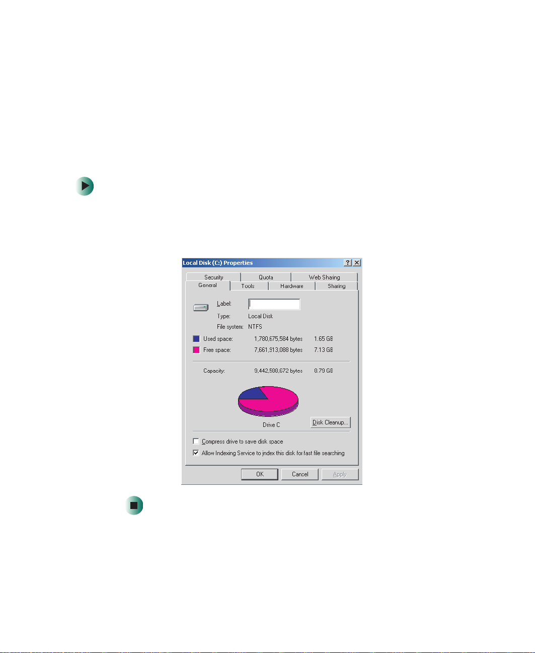
To use Disk Cleanup in Windows 2000 Server:
1 Double-click the My Computer icon.
2 Right-click the hard drive that you want to delete files from, for example
Local Disk (C:), then click
General tab.
3 Click Disk Cleanup. The Disk Cleanup dialog box opens.
4 Make sure that the checkbox next to each file type you want to delete is
selected. For more information about file types you can delete, read the
descriptions in the Disk Cleanup dialog box.
5 Click OK, then click Ye s.
Properties. The Properties dialog box opens at the
Checking the hard drive for errors
Hard drive error-checking programs examine the hard drive for physical flaws
and file and folder problems. These programs correct file and folder problems
and mark flawed areas on the hard drive so the operating system does not use
them. If your server is running an operating system other than
Windows 2000 Server, see the operating system’s documentation for
instructions on checking the hard drive for errors.
To check the hard drive for errors in Windows 2000 Server:
1 Double-click the My Computer icon.
2 Right-click the hard drive that you want to check for errors, for example
Local Disk (C:), then click
24
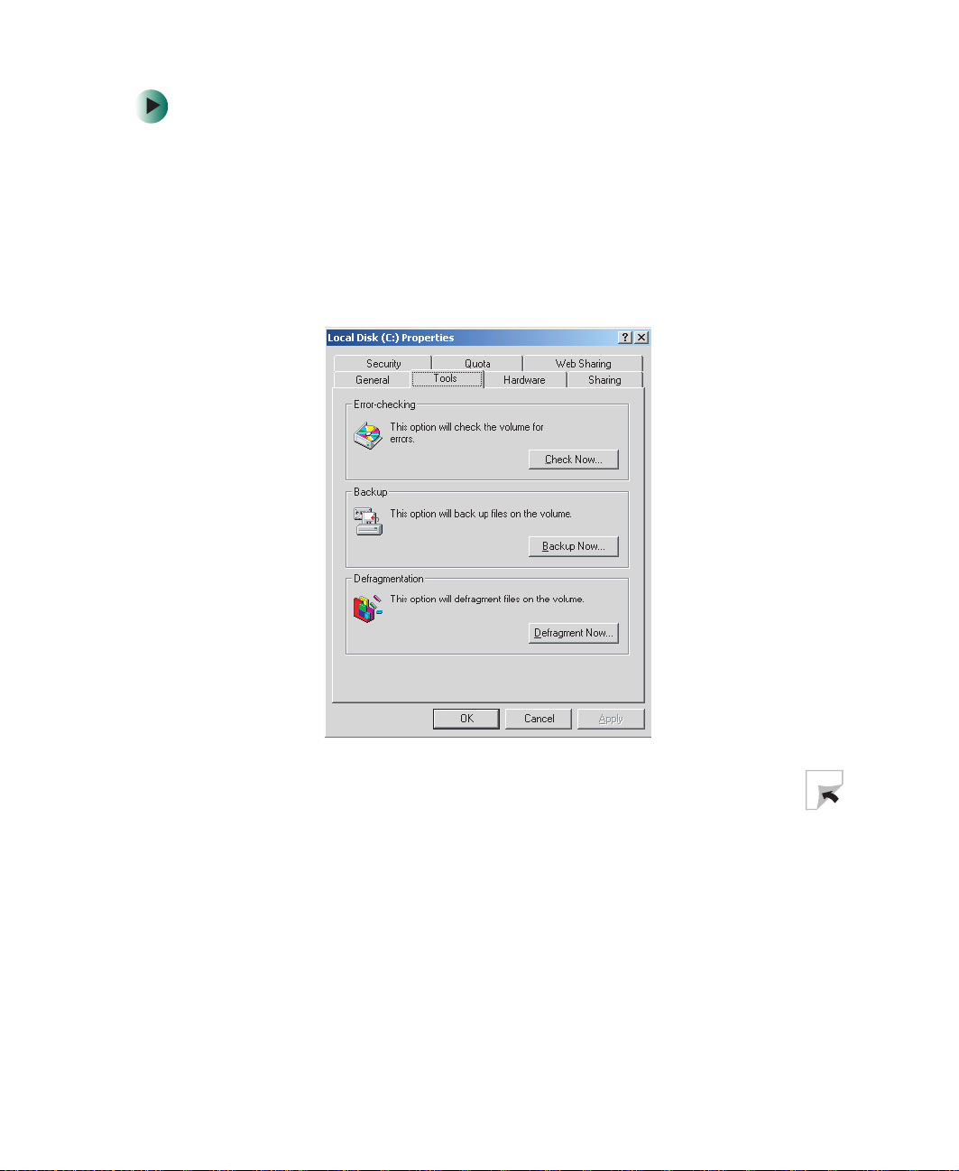
Properties. The Properties dialog box opens.
www.gateway.com

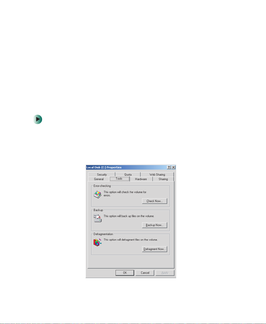
3 Click the Too l s tab.
Managing hard drive space
4 Click Check Now.
5 Click the options to use, then click Start. For help, press F1. Windows
checks the drive for errors. This process may take several minutes.
6 Correct any problems that are found by following the on-screen
instructions. After Windows has finished checking the drive for errors, it
provides a summary of any problems that it may have found.
7 Click OK.
Defragmenting the hard drive
When working with files, your operating system divides the file information
into pieces and stores them in different places on the hard drive. This is called
fragmentation, and it is normal. In order for your server to use a file, your
operating system must search for the pieces of the file and put them back
together. This process slows hard drive performance.
www.gateway.com
25
Chapter 3: Maintaining Your Server
In Windows 2000 Server, the Disk Defragmenter program organizes the data on
the drive so each file is stored as one unit rather than as multiple pieces scattered
across different areas of the drive. Defragmenting the information stored on
the drive can improve hard drive performance.
While Disk Defragmenter is running, do not use your keyboard or mouse
because using them may continuously stop and restart the defragmenting
process. Also, disconnect your server from the network while defragmenting
because network communication may stop the defragmentation process and
cause it to start over.
If your server is running an operating system other than Windows 2000 Server,
see the operating system’s documentation for instructions on defragmenting
files.
To defragment a drive in Windows 2000 Server:
1 Double-click the My Computer icon.
2 Right-click the hard drive that you want to defragment, for example Local
Disk (C:), then click
3 Click the Too l s tab.
Properties. The Properties dialog box opens.
26
www.gateway.com

Managing hard drive space
4 Click Defragment Now.
5 Click Action, then click Defragment.
Disk Defragmenter shows its progress on the screen. When finished, Disk
Defragmenter asks if you want to quit the program.
6 Click Close.
Backing up files
Backing up files and removing them from the hard drive frees space for new
files on the hard drive. It also protects you from losing important information
if the hard drive fails or you accidentally delete files. You should back up your
files regularly to a high-capacity backup device, such as a tape drive. For
information on using your backup device to back up your files, see the device’s
documentation. To buy a tape backup drive visit the accessories store at
accessories.gateway.com
You should also periodically test the reliability of your backup device and
procedures by performing a system restoration using your backup media.
.
www.gateway.com
27

Chapter 3: Maintaining Your Server
Cleaning your server
Keeping your server clean and the vents free from dust helps keep your server
performing at its best. You may want to gather these items and put together a
server cleaning kit:
■ A soft, lint-free cloth
■ Glass cleaner
■ An aerosol can of air that has a narrow, straw-like extension
■ Isopropyl alcohol
■ Cotton swabs
■ A tape drive cleaning cartridge (if a tape drive is installed)
■ A CD drive cleaning kit
Cleaning the exterior
Warning When you shut down your server, the power turns off, but
some electrical current still flows through your server. To
avoid possible injury from electrical shock, unplug the
power cord and all other cables connected to the server.
Always turn off your server and other peripheral devices before cleaning any
components.
Use a damp, lint-free cloth to clean your server and other parts of your system.
Do not use abrasive or solvent cleaners because they can damage the finish on
components.
Your server is cooled by air circulated through the vents on the case, so keep
the vents free of dust. With your server turned off and unplugged, brush the
dust away from the vents with a damp cloth. Be careful not to drip any water
into the vents.
28
www.gateway.com

Cleaning your server
Cleaning the keyboard
You should clean the keyboard occasionally by using an aerosol can of air with
a narrow, straw-like extension to remove dust and lint trapped under the keys.
If you spill liquid on the keyboard, turn off your server and turn the keyboard
upside down. Let the liquid drain, then let the keyboard dry before trying to
use it again. If the keyboard does not work after it dries, you may need to
replace it. Keyboard damage resulting from spilled liquids is not covered by your
warranty.
Cleaning the screen
If your computer screen is a flat panel display, use a soft cloth and water to
clean the computer screen. Squirt a little water on the cloth (never directly on
the screen), and wipe the screen with the cloth.
Warning The computer screen is made of specially coated glass
and can be scratched or damaged by abrasive or
ammonia-based glass cleaners.
- OR -
If your computer screen is not a flat panel display, use a soft cloth and glass
cleaner to clean the monitor screen. Squirt a little cleaner on the cloth (never
directly on the screen), and wipe the screen with the cloth.
Cleaning the tape drive
If you use a tape drive to back up your files, regular maintenance will lengthen
the life of the drive. To maintain the drive’s reliability:
■ Clean the drive monthly with the cleaning cartridge included with
the drive.
■ Remove the tape from the drive whenever the drive is not being
actively used.
www.gateway.com
29
Chapter 3: Maintaining Your Server
Cleaning the mouse
If the mouse pointer begins moving erratically across the screen or becomes
difficult to control precisely, cleaning the mouse will likely improve its accuracy.
If you have an optical mouse, clean the mouse by wiping the bottom of the
mouse with a clean cloth.
If you have a trackball mouse, follow these instructions.
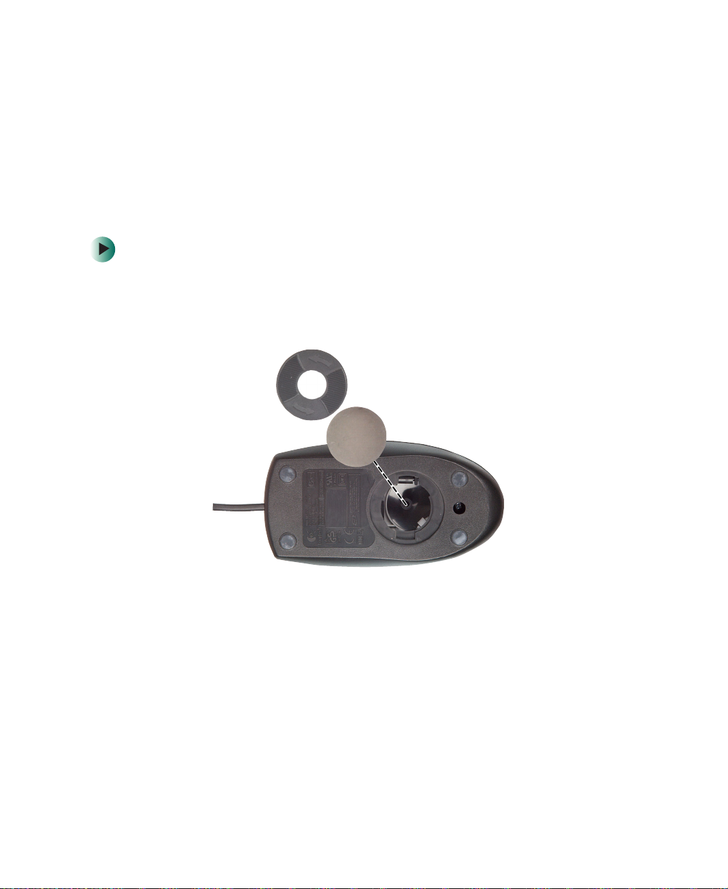
To clean your trackball mouse:
1 Turn the mouse upside down.
2 Rotate the retaining ring on the bottom of the mouse counter-clockwise,
then remove the retaining ring and mouse ball.
30
3 Remove any dust, lint, or dirt from the mouse ball with a soft cloth.
www.gateway.com
Cleaning your server
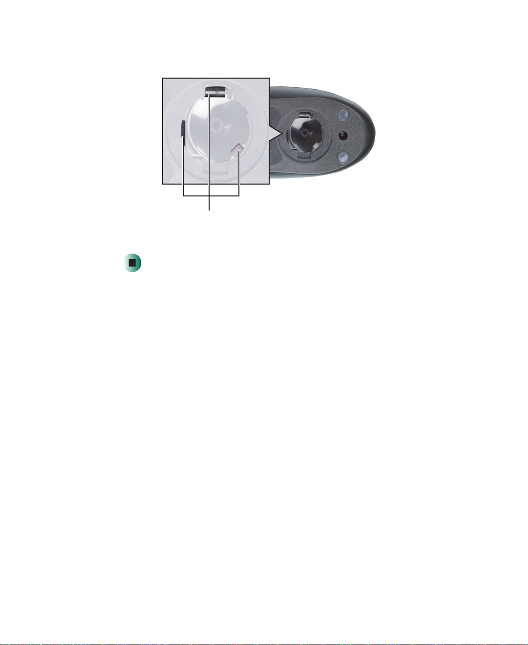
4 Clean the mouse rollers with a cotton swab dipped in isopropyl alcohol.
Mouse rollers
5 Replace the mouse ball and lock the retaining ring into place.
www.gateway.com
31

Chapter 3: Maintaining Your Server
Preparing for system recovery
You should take precautions that will make it easier to reinstall or repair your
operating system if system files become corrupted. These precautions make it
easier to restart your server and recover damaged files.
Creating startup diskettes
If your system files are corrupted, you may not be able to start the server from
the hard drive. Startup diskettes are diskettes that let you start the server and
attempt to fix the problem. If your server is running an operating system other
than Windows 2000 Server, see your operating system’s online help or
documentation for instructions on creating startup diskettes.
To create startup diskettes in Windows 2000 Server:
1 Format four 3.5-inch 1.44 MB diskettes.
2 Insert one diskette into the diskette drive of a computer running any
version of Windows or MS-DOS.
3 Insert the Windows 2000 Server CD into the CD drive.
4 Click Start, then click Run.
5 Type d:\bootdisk\makeboot a: (where d: is the letter assigned to your CD
drive).
6 Click OK, then follow the on-screen prompts.
Creating an emergency repair diskette
Windows 2000 Server lets you create an emergency repair diskette to back up
critical operating system files, including the registry. The emergency repair
diskette is not a bootable diskette. For instructions on using the diskette, see
your Windows 2000 Server documentation or online help.
If your server is running an operating system other than Windows 2000 Server,
see your operating system’s online help or documentation for instructions on
creating repair diskettes.
32
www.gateway.com
Preparing for system recovery
To create an emergency repair diskette in Windows 2000 Server:
1 Format one 3.5-inch 1.44 MB diskette and insert it into your server’s
diskette drive.
2 Double-click the My Computer icon.
3 Right-click the C: drive, then click Properties. The Properties dialog box
opens.
4 Click the Too l s tab.
www.gateway.com
33
Chapter 3: Maintaining Your Server
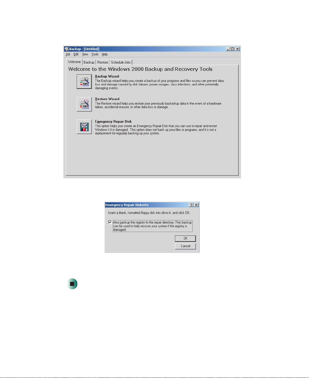
5 Click Backup Now. The Backup window opens.
34
6 Click Emergency Repair Disk. The Emergency Repair Diskette dialog box opens.
7 Click the Also back up the registry to the repair directory check box, then
click
OK. The files are backed up to the diskette.
www.gateway.com

Preparing for system recovery
Keeping a record of system configuration
Recording your operating system configuration
Some operating systems let you print a summary of the configuration of your
server and the memory allocation. This printed summary can provide
information you need to reset your system configuration correctly if the
information is lost. If your server is running an operating system other than
Windows 2000 Server, see the operating system’s documentation for
instructions on recording your system configuration.
To record your operating system configuration in Windows 2000 Server:
1 Click Start, Programs, Administration tools, then click Computer Management.
2 Click System Information. Information about your system appears in the
window to the right. For more specific system information, click on the
appropriate folder under
3 To print a detailed report of your system’s configuration, click Action, then
click
Print.
4 To save a detailed report of your system’s configuration as a text file, click
Action, then click Save As Text File.
System Information.
Recording your BIOS configuration
Some server information can be viewed only in the BIOS Setup utility.
To record your BIOS configuration:
1 Print the appendix for BIOS Settings in this guide.
2 Restart your server, then press F2 when the Gateway logo screen appears
during startup. The BIOS Setup utility opens.
3 Record the BIOS settings on your printout.
www.gateway.com
35

Chapter 3: Maintaining Your Server
System administration
ManageX Event Manager
ManageX lets you manage multiple computers on a Windows 2000 Server or
Novell Netware network from a single window, then implement commands and
policies across the network with a single action. With ManageX you can run
system management tasks which are triggered by certain events or conditions.
You can find additional documentation for ManageX Event Manager on the
Server Companion CD and the ManageX Event Manager CD.
Server security
To prevent unauthorized use of the server, you can set BIOS startup passwords.
To monitor unauthorized access to server components, you can view the event
log.
Using BIOS security passwords
Set up an administrator password to prevent unauthorized access to the BIOS
Setup utility. After you create an administrator password, you can set up a user
password to prevent unauthorized access to the server. After you set up
passwords, you must enter the correct password to start the server and the BIOS
Setup utility.
■ Enter either password to finish starting the server.
■ Enter the administrator password for access to the BIOS Setup utility.
To set the BIOS security passwords:
1 Restart your server, then press F2 when the Gateway logo screen appears
during startup. The BIOS Setup utility opens.
2 Select the Security menu.
3 Select the password to set according to the following table.
36
www.gateway.com

System administration
Option Description
Supervisor password To control access to system configuration, set a
supervisor password. Using a supervisor password lets
you make changes to any setting in the BIOS.
Passwords can be temporarily disabled. To bypass the
passwords, see “Bypassing the BIOS passwords” on
page 77.
User password To control access to the server, set a user password. The
supervisor can set the level of access granted to the user
password. The user password access levels are:
■
No Access. User cannot access the BIOS Setup utility.
■
Limited. User can change only the date and time.
■
View Only. User can see all settings, but cannot
change them.
■
Full. User can change every setting except the
supervisor password.
Passwords can be temporarily disabled. To bypass the
passwords, see “Bypassing the BIOS passwords” on
page 77.
4 Type the password and press ENTER, then type it again and press ENTER.
5 Exit the BIOS Setup utility.
For information about bypassing BIOS passwords, see “Bypassing the BIOS
passwords” on page 77.
Monitoring case access
Whenever the server’s case cover is removed, the intrusion switch is activated
and an event is recorded in the event log.
To view the event log:
1 Restart your server, then press F2 when the Gateway logo screen appears
during startup. The BIOS Setup utility opens.
2 Open the Advanced menu, select Event Log Configuration, then select Event
Log Area
. The event log is shown on the screen.
www.gateway.com
37

Chapter 3: Maintaining Your Server
Using your Server Companion CD
You can use your Server Companion CD to:
■ Install hardware drivers
■ Install programs
■ View server documentation
Instructions for using the CD are provided in Using Your Server Companion CD.
38
www.gateway.com

Installing
Components
Read this chapter to learn how to:
■ Open and close the server case
■ Install drives
■ Install memory modules
■ Install expansion cards
■ Replace the processor
■ Replace the power supply
■ Replace the system board
■ Replace the rear case fan
■ Replace the CMOS battery
You must open your server case to install components. If
you are not comfortable with these procedures, get help
from a more experienced computer user or computer
service technician, or contact Gateway Technical Support.
4
39

Chapter 4: Installing Components
Preparing to install components
Selecting a place to work
Work on your server in an area that:
■ Is clean (avoid dusty areas)
■ Is a low-static environment (avoid carpeted areas)
■ Has a stable surface on which to set your server
■ Has enough room to place all of your server parts
■ Is near a grounded outlet so you can test your server after installation
■ Is near a telephone (in case you need help from Gateway Technical
Support). The telephone must be directly connected to a telephone jack
and cannot be connected to your server.
Gathering the tools you need
Some tools and supplies that you may need to work on your server are:
■ A notebook to take notes
■ A Phillips screwdriver
■ A small flat-blade screwdriver
■ Small containers to store various types of screws
■ A grounding wrist strap (available at most electronic stores)
40
www.gateway.com

Preventing static electricity discharge
Preventing static electricity
discharge
The components inside your server are extremely sensitive to static electricity,
also known as electrostatic discharge (ESD).
Warning ESD can permanently damage electrostatic
discharge-sensitive components in the server. Prevent
ESD damage by following ESD guidelines every time you
open the server case.
Warning To avoid exposure to dangerous electrical voltages and
moving parts, turn off your server and unplug the power
cord and modem and network cables before opening the
server case.
Before working with server components, follow these guidelines:
■ Turn off the server, then unplug the power cord and all other cables.
■ Drain any residual power from the server by pressing the power button.
■ Wear a grounding wrist strap (available at most electronics stores) and
attach it to a bare metal part of the server. You can also touch a bare metal
surface on the back of the server with your finger.
Warning To prevent risk of electric shock, do not insert any object
into the vent holes of the power supply.
■ Avoid static-causing surfaces such as carpeted floors, plastic, and packing
foam.
■ Avoid working on the server when your work area is extremely humid.
■ Remove components from their antistatic bags only when you are ready
to use them. Do not lay components on the outside of antistatic bags
because only the inside of the bags provide electrostatic protection.
■ Always hold expansion cards by their edges or their metal mounting
brackets. Avoid touching the edge connectors and components on the
cards. Never slide expansion cards or components over any surface.
www.gateway.com
41
Chapter 4: Installing Components
Opening the server case
Because the components inside your server are extremely sensitive to static
electricity, make sure that you follow the instructions at the beginning of this
chapter to avoid static electricity damage.
Warning For correct cooling and air flow, always reinstall the side
panel before you turn on the server. Operating the server
without the cover in place can damage server components.
To open the server case:
1 Follow the instructions in “Preventing static electricity discharge” on
page 41.
2 Turn off the server, then disconnect the power cord and all other cables
connected to the server.
3 For more stability, place the server on its side.
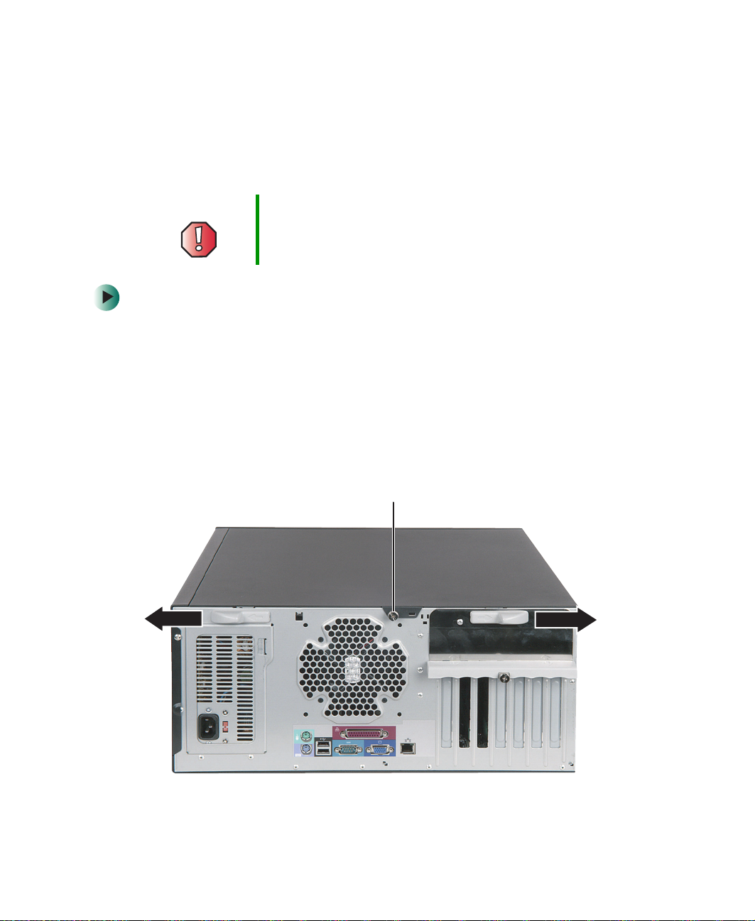
4 If your case has a shipping thumbscrew installed on the back, remove the
screw, then push the cover release latches away from each other.
42
Shipping thumbscrew
www.gateway.com
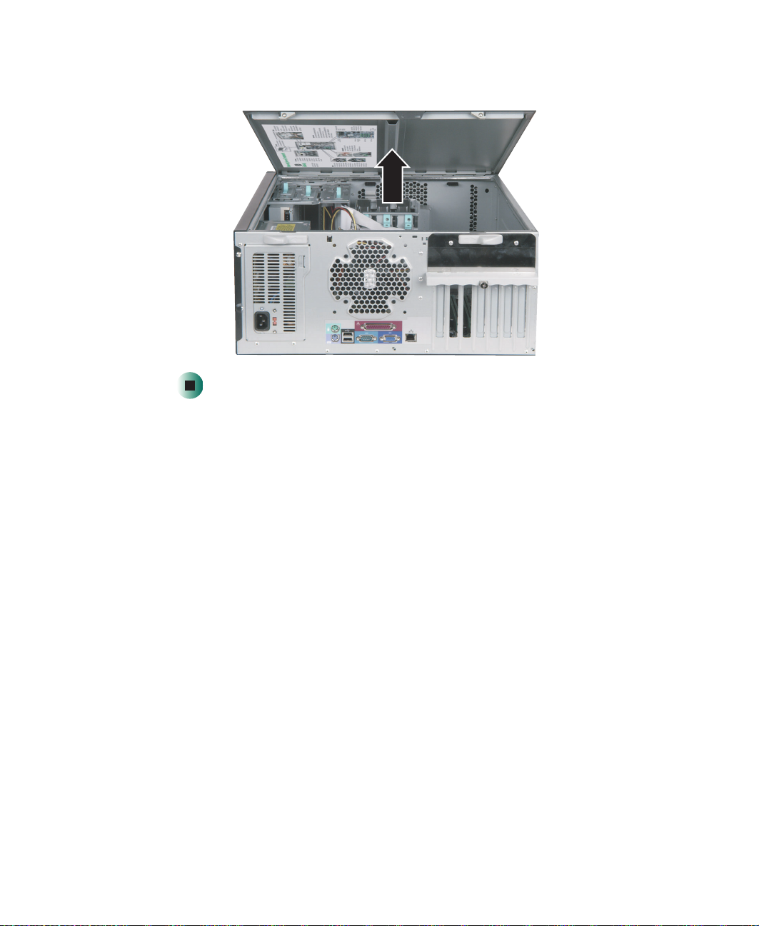
5 Swing the side panel away from the case.
Opening the server case
www.gateway.com
43

Chapter 4: Installing Components
Closing the server case
To close the server case:
1 For more stability, place the server on its side.
2 Make sure that all of the internal cables are arranged inside the case so
they will not be pinched when you close the server case.
3 Align the side panel’s front tabs into the case notches, then swing the side
panel toward the case until the release latches snap into place.
4 Return the case to its upright position.
5 Reconnect the power cord and all other cables.
44
www.gateway.com

Installing drives
Your server comes with a CD drive and a 3.5-inch diskette drive. One additional
5.25-inch drive bay and one additional 3.5-inch drive bay are also provided for
adding drives.
CD drive
5.25-inch drive bay
3.5-inch drive bay
3.5-inch diskette drive
Installing drives
As you prepare to install drives, remember:
■ Before you install a drive, see the drive’s documentation for information
on configuring the drive, setting drive jumpers, and attaching cables.
■ If you are installing a drive that requires a controller card, install the card
before you install the drive.
www.gateway.com
45

Chapter 4: Installing Components
■ IDE hard drives can be configured as single, master, slave, or cable-select.
IDE CD drives can be configured as master, slave, or cable-select.
■ If cable-select is available (drive assignments will be marked on the
cable), the IDE cable assigns the master/slave positions to the drives
it connects. You can override these assignments using the jumpers on
the drives.
■ If you are connecting two IDE drives to the cable, connect the middle
cable connector to the slave drive and connect the end cable
connector to the master (boot) drive.
■ If cable-select is not available and only one drive is attached to an IDE
controller cable, configure the drive as master if it is a CD drive. If
two drives of any type are attached to the cable, configure one as
master and one as slave.
■ You may need to configure the drives you install using the BIOS Setup
utility. Press F2 at startup to open the BIOS Setup utility.
Installing a CD or diskette drive
Important Drives connected to the primary and secondary IDE
connectors should be ATA100 drives, and drives
connected to the third IDE connector should be ATA66
drives.
To install a CD or diskette drive:
1 Follow the instructions in “Preventing static electricity discharge” on
page 41.
2 Open the server case by following the instructions in “Opening the server
case” on page 42.
3 If you are replacing a drive, go to Step 6.
- OR -
46
www.gateway.com

Installing drives
If you are adding a new drive, press in on the two front cover release tabs,
then swing the front cover away from the server.
4 Press the drive bay face plate release tab, then swing the faceplate away
from the front cover.
www.gateway.com
47

Chapter 4: Installing Components
5 Remove the shield for the bay into which you are installing the new drive.
Shields
48
6 If you are replacing a drive, disconnect the drive cables.
7 If there is a shipping thumbscrew installed next to the drive release latch,
remove the thumbscrew.
Shipping thumbscrew
www.gateway.com
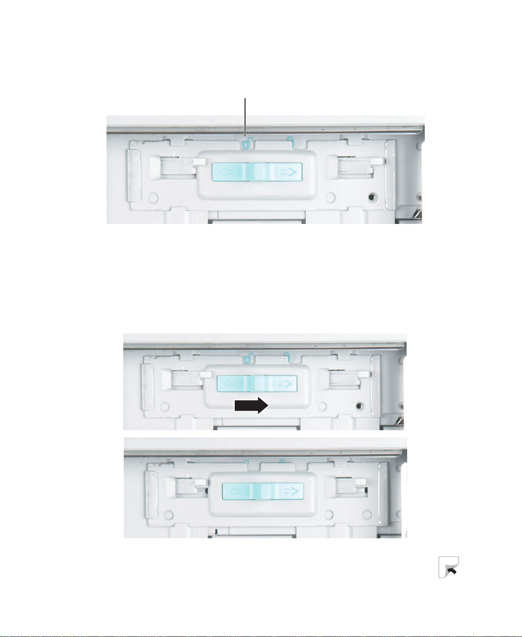
Installing drives
8 Slide the drive release latch back toward the rear of the case until the unlock
icon is visible.
Unlock icon
9 If you are replacing a drive, slide it forward and out of the drive bay.
10 Set any jumpers on the new drive. See the drive’s documentation for further
instructions.
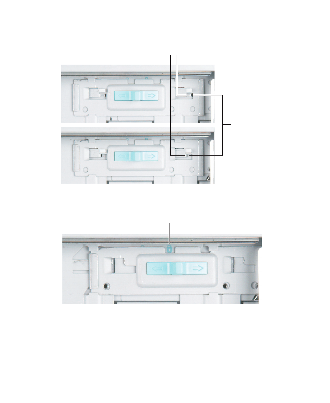
11 Slide the new drive into the drive bay.
12 Move the release latch to the right about ¼ inch (6 mm).
www.gateway.com
49
Chapter 4: Installing Components
13 Align the drive’s screw holes with the release latch’s locking tabs.
14 Slide the drive release latch toward the front of the case until the lock icon
is visible.
Locking tabs
Drive screw
holes
Lock icon
15 Connect the drive cables by following the instructions in the drive’s
documentation.
50
www.gateway.com
16 If you removed the front cover, replace it.
17 Close the server case by following the instructions in “Closing the server
case” on page 44.
Installing a hard drive
Important Drives connected to the primary and secondary IDE
connectors should be ATA100 drives, and drives
connected to the third IDE connector should be ATA66
drives.
To install a hard drive:
1 Follow the instructions in “Preventing static electricity discharge” on
page 41.
2 Open the server case by following the instructions in “Opening the server
case” on page 42.
Installing drives
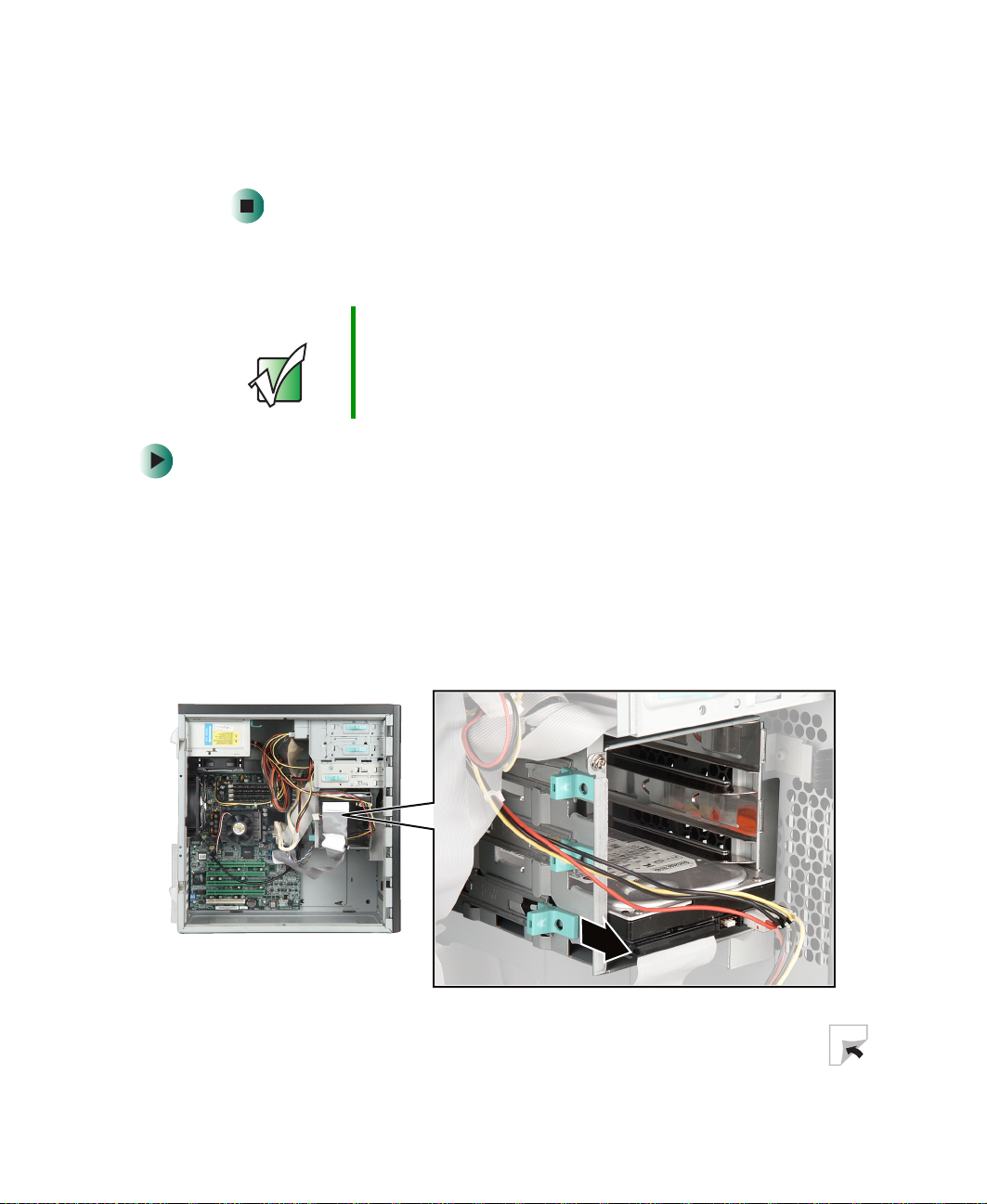
3 If you are replacing a hard drive, disconnect the old drive’s cables.
4 Slide the drive release latch toward the open side of the case.
www.gateway.com
51

Chapter 4: Installing Components
5 If you are replacing a hard drive, slide the old drive out of the drive bay.
6 Set any jumpers on the new drive. See the drive’s documentation for further
instructions.
52
7 Slide the new drive in, then slide the release latch toward the inside of
the case.
www.gateway.com

Installing drives
8 Connect the drive cables by following the instructions in the drive’s
documentation.
9 Close the server case by following the instructions in “Closing the server
case” on page 44.
www.gateway.com
53

Chapter 4: Installing Components
Installing memory
When you upgrade your server memory, make sure that you install the correct
type of memory module for your server. Your server uses PC2100 DDR SDRAM
registered ECC DIMM memory. The following illustration shows the location
of the memory modules on the system board.
Warning Use only PC2100 DDR SDRAM registered ECC DIMM
memory modules.
Memory
module slots
54
www.gateway.com

Installing memory
To install or replace memory:
1 Follow the instructions in “Preventing static electricity discharge” on
page 41.
2 Open the server case by following the instructions in “Opening the server
case” on page 42.
3 Pull the plastic tabs away from the sides of the memory module slot. If
you are replacing a memory module, remove the old module.
4 Align the notch on the new module with the notch in the memory module
slot and press the module firmly into the slot. The tabs on the sides of
the memory slot should secure the memory module automatically.
5 Close the server case by following the instructions in “Closing the server
case” on page 44.
6 Turn on the server. Make sure that the server turns on and that the
operating system loads completely.
7 If your server is running Windows 2000 Server, right-click the My Computer
icon, then click
at the bottom of the Properties dialog.
- OR -
Restart and open the BIOS Setup utility. Note the
the Main menu to verify the amount of memory installed.
Properties. The amount of memory in your server is shown
System Memory listed in
www.gateway.com
55

Chapter 4: Installing Components
Installing PCI expansion cards
A PCI expansion card (sometimes called an add-in card) is a card used in the server
to add functionality to the system. Use the following procedure to replace, add,
or reseat an expansion card.
To replace, add, or reseat a PCI expansion card:
1 Follow the instructions in “Preventing static electricity discharge” on
page 41.
2 Open the server case by following the instructions in “Opening the server
case” on page 42.
3 If you are replacing a card, disconnect any cables that are attached to the
old card.
4 Remove the thumbscrew that secures the expansion card retention cover
to the server case.
56
Thumbscrew
www.gateway.com

Installing PCI expansion cards
5 While holding the retention cover open, remove the expansion card. You
can slightly seesaw the card end-to-end to loosen the card, but do not bend
the card sideways.
Warning Do not touch the contacts on the bottom part of the
expansion card. Touching the contacts can cause
electrostatic damage to the card.
6 While holding the retention cover open, press the new card into the
expansion slot. You can slightly seesaw the card end-to-end to help insert
the card, but do not bend the card sideways.
7 Push the retention cover in, then tighten the thumbscrew.
8 Connect any cables to the card by following the instructions in the card
documentation.
9 Close the server case by following the instructions in “Closing the server
case” on page 44.
10 See the documentation that came with the card for any special software
installation instructions.
www.gateway.com
57

Chapter 4: Installing Components
Replacing the processor
Your server is compatible with the Intel® Pentium®4 or Intel® Celeron®
processor. The server automatically detects the processor each time you turn
on the server. Whenever you install a new processor, you should first install
the most current version of the BIOS. For more information, see “Updating the
BIOS” on page 73.
Warning A heat sink must be installed on the processor. Installing
a processor without a heat sink could damage the
processor.
Warning The processor and heat sink may be hot if the computer
has been running. Also, there may be sharp edges on the
heat sink. Consider wearing protective gloves.
To replace the processor:
1 Install the most current BIOS version by following the instructions in
“Updating the BIOS” on page 73.
58
2 Follow the instructions in “Preventing static electricity discharge” on
page 41.
3 Open the server case by following the instructions in “Opening the server
case” on page 42.
www.gateway.com
Replacing the processor
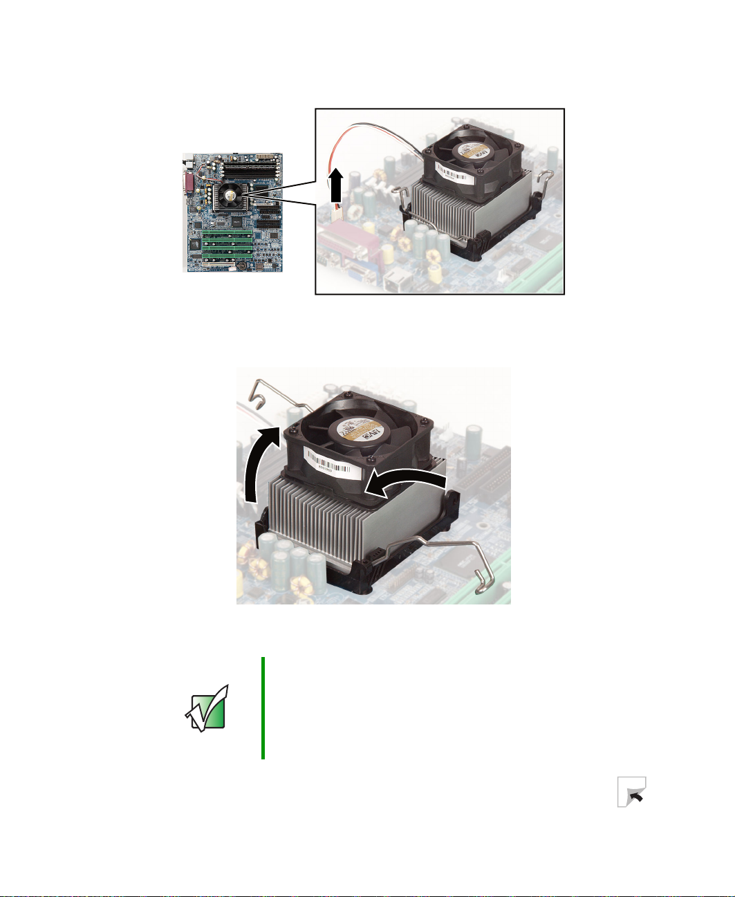
4 Unplug the heat sink’s cooling fan from the system board.
5 Press down on the heat sink locking levers, push them slightly away from
the heat sink, then lift the levers out of the way.
6 Remove the heat sink.
Important The heat sink mounting paste may harden over time and
hold the heat sink securely to the processor. If removing
the heat sink also pulls the processor out of the processor
socket, the processor should still be undamaged. Rotate
the processor locking lever out of the way and continue
with the procedure in Step 9.
www.gateway.com
59

Chapter 4: Installing Components
7 Press down on the processor locking lever, push it slightly away from the
processor, then rotate the lever straight up to release the processor.
8 Remove the old processor.
9 Install the new processor into the system board. Make sure that the arrow
on the corner of the processor aligns with Pin 1 on the processor socket
(the socket corner without a pin hole).
10 Press the processor locking lever down until it clicks into place.
11 Apply thermal grease to the top of the processor, if necessary.
12 Place the heat sink on the processor, then press the heat sink locking levers
down until they click into place.
13 Plug the heat sink’s cooling fan into the system board.
14 Close the server case by following the instructions in “Closing the server
case” on page 44.
60
www.gateway.com
Replacing the power supply
Replacing the power supply
Warning The power supply in this server contains no
user-serviceable parts. Only a qualified computer
technician should service the power supply.
Your server is supplied with a 3-wire AC power cord fitted
with the correct plug style for your region. If this plug does
not match the connector on your surge protector, UPS, or
wall outlet, do not attempt to modify the plug in any way.
Use a surge protector, UPS, or wall outlet that is
appropriate for the supplied AC power cord.
To replace the power supply:
1 Follow the instructions in “Preventing static electricity discharge” on
page 41.
2 Open the server case by following the instructions in “Opening the server
case” on page 42.
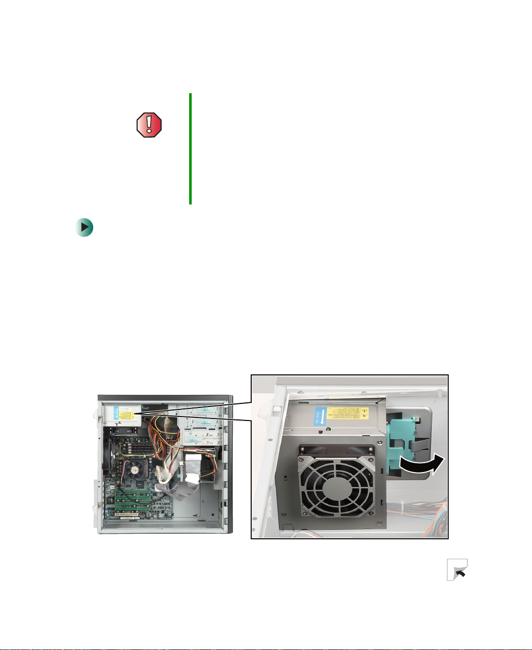
3 Disconnect the power supply cables from all components, noting their
locations and orientation. (You will reconnect the cables after you install
the new power supply.)
4 Pull the power supply retention clip away from the power supply.
www.gateway.com
61
Chapter 4: Installing Components
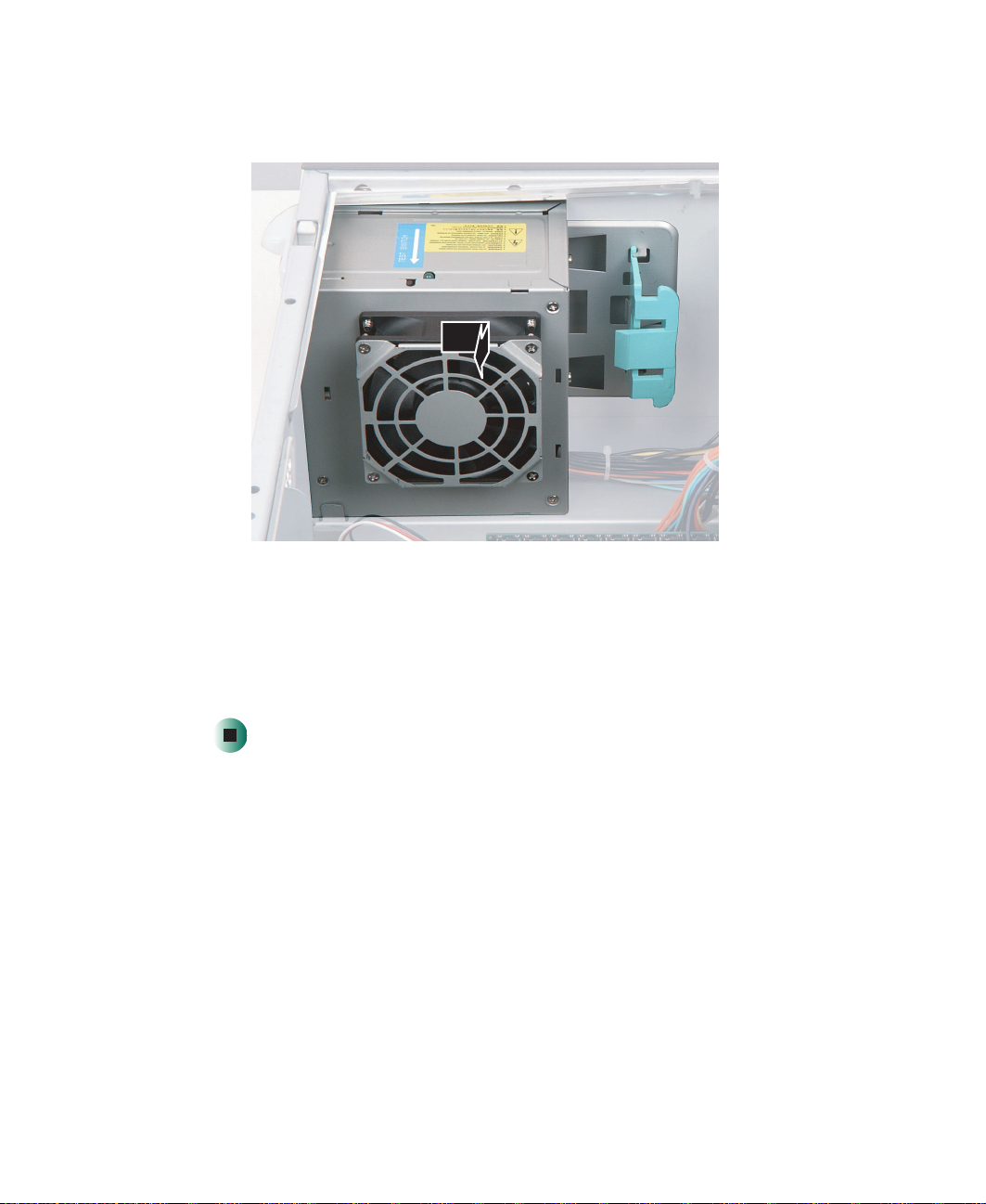
5 While supporting the power supply with your hand, slide the power supply
toward the front of the case, then out toward the bottom of the case.
6 Install the new power supply, then press the retention clip back against
the case.
62
7 Reconnect the power supply cables.
8 Close the server case by following the instructions in “Closing the server
case” on page 44.
www.gateway.com
Replacing the system board
Replacing the system board
To replace the system board:
1 Follow the instructions in “Preventing static electricity discharge” on
page 41.
2 Open the server case by following the instructions in “Opening the server
case” on page 42.
3 Remove all of the expansion cards by following the instructions in
“Installing PCI expansion cards” on page 56.
4 Unplug the heat sink’s cooling fan, then remove the heat sink and
processor by following the instructions in “Replacing the processor” on
page 58.
5 Remove the memory modules by following the instructions in “Installing
memory” on page 54.
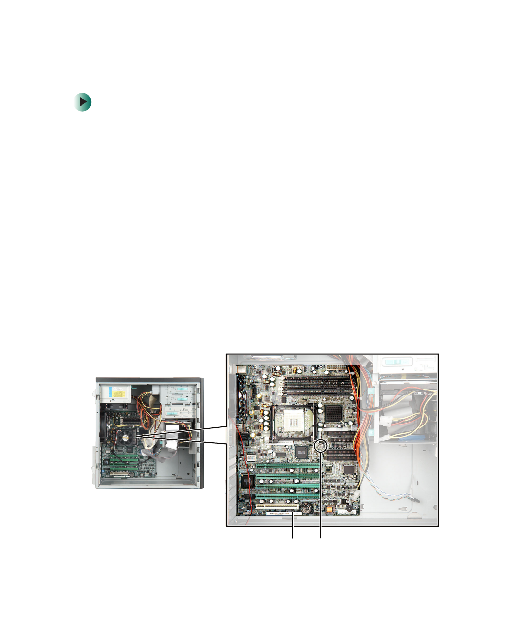
6 Disconnect the power and data cables from the system board, noting their
locations and orientation. (You will reconnect the cables after you install
the new board.) Make sure that you disconnect the intrusion switch cable.
7 Remove the system board’s thumbscrew.
www.gateway.com
ThumbscrewIntrusion switch connector
63
Chapter 4: Installing Components
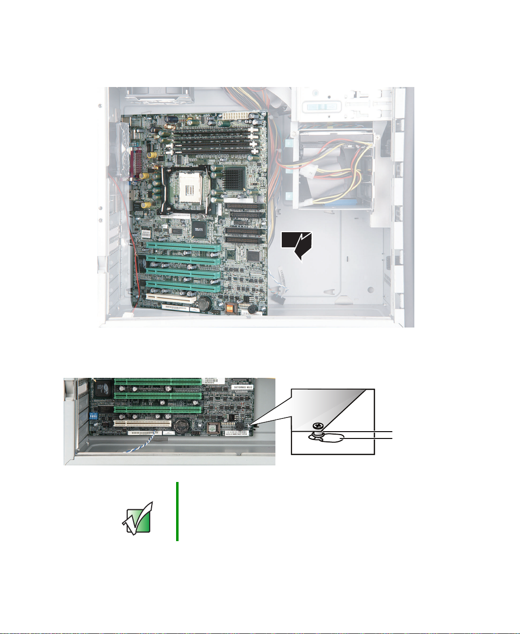
8 Slide the system board toward the front of the case, then lift it away from
the case.
9 Slide the new system board’s standoffs into the keyhole slots, then slide
the board toward the back of the case.
Important The new system board must have special standoffs
pem studs
(
necessary, use the standoffs from the original system
board.
) mounted on the bottom of the board. If
10 Lock the system board into place with the thumbscrew.
64
www.gateway.com
Standoff
Keyhole slot

Replacing the system board
11 Install the memory, processor, and heat sink, then reconnect the heat sink
cooling fan to the system board.
12 Connect the power and data cables.
13 Install the expansion cards by following the instructions in “Installing PCI
expansion cards” on page 56.
14 Close the server case by following the instructions in “Closing the server
case” on page 44.
15 Turn on your server.
16 Press F2 when the Gateway logo screen appears during startup. The BIOS
Setup utility opens.
17 Check BIOS settings to make sure that they detect the server’s new
hardware, then save your changes (if any) and close the BIOS Setup utility.
www.gateway.com
65
Chapter 4: Installing Components
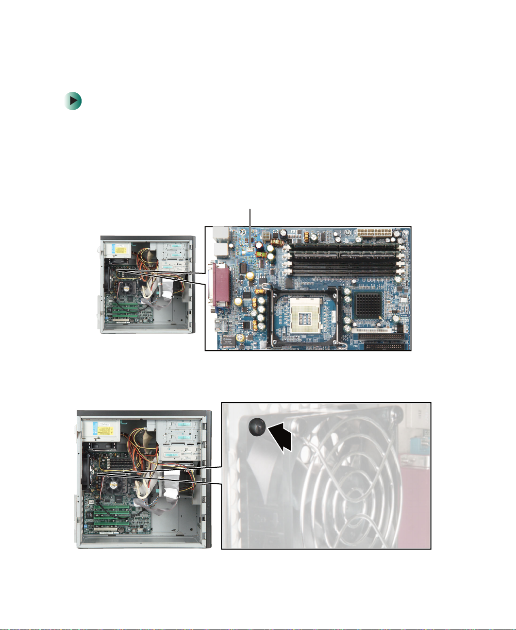
Replacing the case fan
To replace the case fan:
1 Follow the instructions in “Preventing static electricity discharge” on
page 41.
2 Open the server case by following the instructions in “Opening the server
case” on page 42.
3 Unplug the case fan from the system board.
Rear fan connector
66
4 Use a narrow tool, such as a small screwdriver, to push each of the four
fan mounting rivets and sleeves out toward the back of the case.
www.gateway.com
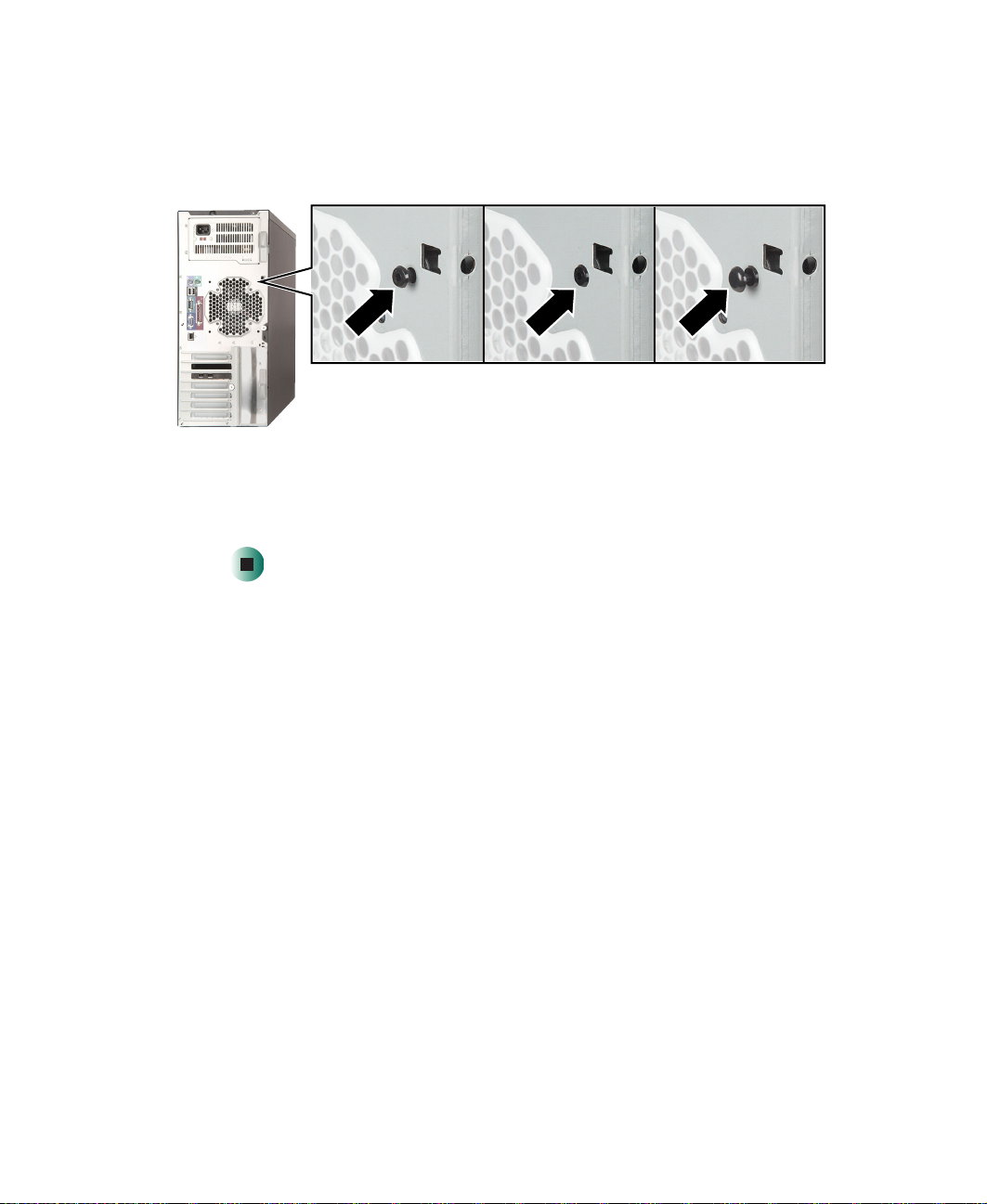
Replacing the case fan
5 Remove each rivet, then remove the old fan.
6 Hold the new fan in place while you push the fan’s rivet sleeves into the
fan from the outside of the case, then push the rivets into the sleeves.
7 Reconnect the case fan to the system board.
8 Close the server case by following the instructions in “Closing the server
case” on page 44.
www.gateway.com
67

Chapter 4: Installing Components
Replacing the CMOS battery
If the server clock does not keep time or the settings in the BIOS Setup utility
are not saved when you turn off the server, replace the CMOS battery with an
equivalent battery.
Warning Danger of explosion if battery is incorrectly replaced.
Replace only with the same or equivalent type
recommended by the manufacturer. Dispose of used
batteries following the manufacturer’s instructions.
To replace the battery:
1 Print the appendix for BIOS Settings in this guide.
2 Open the BIOS Setup utility by following the instructions in “Opening the
BIOS Setup utility” on page 72.
3 Record the BIOS settings on your printout, then exit from the utility. For
more information, see “Recording your BIOS configuration” on page 35.
4 Turn off your server, then follow the instructions in “Preventing static
electricity discharge” on page 41.
68
5 Open the server case by following the instructions in “Opening the server
case” on page 42.
6 Locate the old battery on the system board and note its orientation. You
will need to install the new battery the same way.
Battery
www.gateway.com

Replacing the CMOS battery
7 Place the edge of a small flat-head screwdriver under the battery and lift
the battery up until it comes out of the socket.
8 Make sure that the positive (+) side of the new battery is facing up, then
press the new battery into the socket until it snaps into place.
9 Close the server case by following the instructions in “Closing the server
case” on page 44.
10 Turn on t he server.
11 When the Gateway Logo screen appears, press F2 to open the BIOS Setup
utility.
12 Restore any BIOS settings that you wrote down in Step 3.
13 Save all your settings and close the BIOS Setup utility.
www.gateway.com
69

Chapter 4: Installing Components
70
www.gateway.com

Using the BIOS
Setup Utility
Read this chapter to learn how to:
■ Open the BIOS Setup utility
■ Update the BIOS
■ Reset the BIOS settings to their factory defaults
■ Bypass the BIOS passwords
5
71

Chapter 5: Using the BIOS Setup Utility
Opening the BIOS Setup utility
The BIOS Setup utility stores basic settings for your server. These settings include
basic hardware configuration, resource settings, and password security. These
settings are stored and saved even when the power is off.
Caution The options in the BIOS Setup utility have been set at the
factory for optimal performance. Changes to these
settings will affect the performance of your server.
Before changing any settings, write them down in case you
need to restore them later. You can record the settings on
a printout of the appendix for “BIOS Settings” on
page 123.
To open the BIOS Setup utility:
1 Restart your server, then press F2 when the Gateway logo screen appears
during startup. The BIOS Setup utility opens.
When you select menu items, the Item Specific Help box on the right side
of the screen displays specific information about the selection. The
command bar across the bottom of the screen shows the keys you press
to access help, navigate through the menus, and perform other tasks.
72
2 Select one of these menus:
■ Main gives you access to basic information and settings related to your
server’s hardware and configuration.
■ Advanced gives you access to information and settings for system
resources, hardware, and server’s configuration.
■ Power gives you access to settings that control your server’s power
management features.
■ Boot lets you change startup settings.
■ Security gives you access to settings related to system access passwords.
For more information, see “Server security” on page 36.
■ Exit gives you access to options for closing the BIOS Setup utility.
www.gateway.com

Updating the BIOS
If you need a new version of the BIOS, you can download the BIOS update from
Gateway, then install the new version from a diskette.
To update the BIOS:
1 Print the appendix for BIOS Settings in this guide.
2 Download the BIOS update from support.gateway.com.
3 Restart your server, then press F2 when the Gateway logo screen appears
during startup.
4 Record any custom BIOS settings on your printout.
5 Follow the instructions in the self-extracting BIOS update file.
6 Enter any custom BIOS settings you recorded in Step 4, then save your
changes and close the BIOS Setup utility.
Updating the BIOS
Recovering the BIOS
If you encounter a problem while you are updating the BIOS, such as a power
outage, the BIOS update may not be successful. You can try to recover the BIOS
by setting a system board jumper.
To recover the BIOS:
1 Follow the instructions in “Preventing static electricity discharge” on
page 41.
2 Turn off the server, then disconnect the power cord and all other cables
connected to the server.
3 Remove the side panel. For more information, see “Opening the server
case” on page 42.
www.gateway.com
73
Chapter 5: Using the BIOS Setup Utility
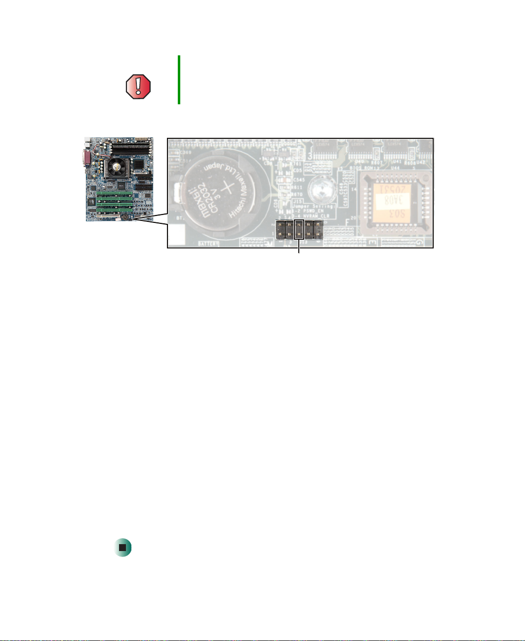
Warning Moving the jumper while the power is on can damage your
server. Always turn off the server and unplug the power
cord and all other cables before changing the jumper.
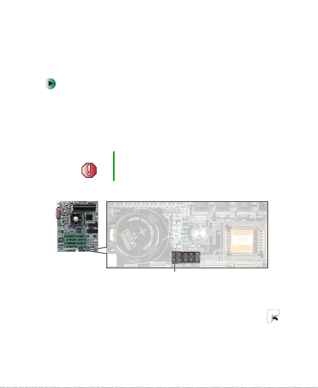
4 Place the jumper across pins 5-6 of jumper J13.
5 Close the case, then reconnect the power cord, monitor, and keyboard. For
more information, see “Closing the server case” on page 44.
Jumper pins 5-6
6 Place the startup diskette containing the BIOS files into drive A:.
7 Turn on the server. At the start of the BIOS recovery process, the server
beeps once. The recovery process may take a few minutes.
8 When prompted, remove the diskette and turn off the server.
9 Disconnect the power cord and remove the side panel again. Remove the
jumper from pins 5-6 of jumper J13, and place it over just one of the pins
for storage.
10 Close the case, reconnect the power cord and all other cables, then turn
on the server.
11 When the Gateway Logo screen appears, press F2 to open the BIOS Setup
utility.
12 In the BIOS Setup utility, go to the appropriate menus and select any BIOS
fields you want to change. Make sure that the date and time are correct.
13 Save your changes, then close the BIOS Setup utility.
74
www.gateway.com
Resetting the BIOS
The Reset BIOS jumper on the system board lets you return all BIOS settings
to the factory defaults.
To reset the BIOS:
1 Print the appendix for BIOS Settings in this guide.
2 Restart your server, then press F2 when the Gateway logo screen appears
during startup. The BIOS Setup utility opens.
3 Record any custom BIOS settings on your printout.
4 Follow the instructions in “Preventing static electricity discharge” on
page 41.
5 Turn off the server, then disconnect the power cord and all other cables
connected to the server.
6 Remove the side panel. For more information, see “Opening the server
case” on page 42.
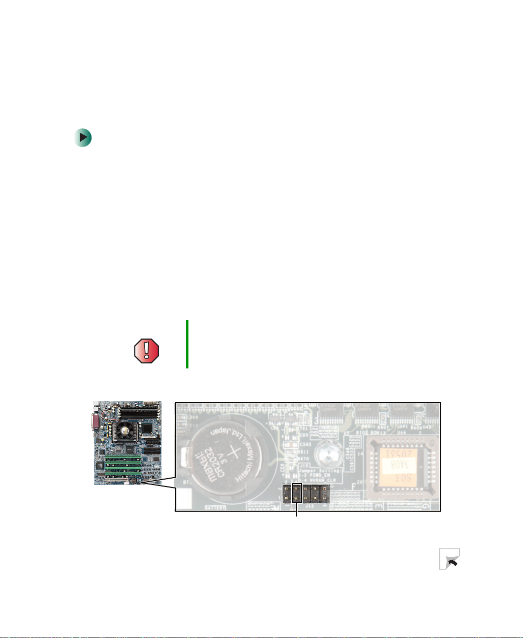
Resetting the BIOS
Warning Moving the jumper while the power is on can damage your
server. Always turn off the server and unplug the power
cord and all other cables before changing the jumper.
7 Place the jumper across pins 3-4 of jumper J13.
Jumper pins 3-4
www.gateway.com
75

Chapter 5: Using the BIOS Setup Utility
8 Close the case, then reconnect the power cord, monitor, and keyboard. For
more information, see “Closing the server case” on page 44.
9 Turn on the server. A message appears saying that the CMOS Checksum
is bad, which means the BIOS has been cleared successfully.
10 Press F2 to load the default BIOS values and open the BIOS Setup utility.
All BIOS settings return to factory defaults, and all BIOS passwords are
erased.
11 Turn off the server, disconnect the power cord, and remove the side panel
again.
12 Remove the jumper from pins 3-4 of jumper J13 and place it over just one
of the pins for storage.
13 Close the case, reconnect the cords, then turn on the server.
76
www.gateway.com
Bypassing the BIOS passwords
Bypassing the BIOS passwords
The Bypass Password jumper on the system board lets you bypass the BIOS
passwords.
To bypass the BIOS passwords:
1 Follow the instructions in “Preventing static electricity discharge” on
page 41.
2 Turn off the server, then disconnect the power cord and all other cables
connected to the server.
3 Remove the side panel. For more information, see “Opening the server
case” on page 42.
Warning Moving the jumper while the power is on can damage your
server. Always turn off the server and unplug the power
cord and all other cables before changing the jumper.
4 Place the jumper across pins 1-2 of jumper J13.
Jumper pins 1-2
5 Close the case, then reconnect the power cord, monitor, and keyboard. For
more information, see “Closing the server case” on page 44.
www.gateway.com
77

Chapter 5: Using the BIOS Setup Utility
6 Turn on the server. You can now open the BIOS Setup utility or perform
other server tasks.
If you want to change the passwords, press F2 when the Gateway logo
screen appears. When the BIOS Setup utility opens, you can clear or change
the passwords, or change other BIOS settings.
7 Turn off the server, disconnect the power cord, and remove the side panel
again.
8 Remove the jumper from pins 1-2 of jumper J13 and place it over just one
of the pins for storage.
9 Close the case, reconnect the cords, then turn on the server.
78
www.gateway.com

Troubleshooting
Read this chapter to learn how to:
■ Interpret error messages and codes
■ Troubleshoot
■ Get telephone support and training
If the suggestions in this chapter do not correct the
problem, see “Telephone support” on page 103 for more
information about how to get help.
6
79

Chapter 6: Troubleshooting
Safety guidelines
While troubleshooting your server, follow these safety guidelines:
■ Never remove the side panel while your server is turned on and while the
modem cable, network cable, and the power cord are connected.
■ Do not attempt to open the monitor. To do so is extremely dangerous. Even
if the power is disconnected, energy stored in the monitor components
can be dangerous. Also, opening the monitor voids the warranty.
■ Make sure that you are grounded correctly before opening the server case.
For more information about preventing damage from static electricity, see
“Preventing static electricity discharge” on page 41.
■ After you complete any maintenance task where you have to open the
server case, make sure that you close the case, reinstall any screws, then
reconnect all cables before you restart your server.
Warning To avoid bodily injury, do not attempt to troubleshoot your
server problem if:
■
Power cords or plugs are damaged
■
Liquid has been spilled into your server
■
Your server was dropped
■
The case was damaged
Instead, unplug your server and contact a qualified
computer technician. If your server was damaged during
shipment from Gateway, contact Gateway Technical
Support.
80
www.gateway.com

Error messages
These messages often indicate procedural errors such as typing an incorrect
keystroke or trying to save a file to a write-protected diskette. Some messages,
however, may indicate a problem that requires further troubleshooting.
Access denied
■ Your diskette is write-protected. Move the write-protection tab over the
window on the back of the diskette, or save to a new diskette.
Bad command or file name
■ Make sure that you entered the right command.
■ Make sure that the specified drive is correct, then try again.
■ If you are trying to exit MS-DOS to return to Windows, type exit, then
press E
Base memory [xxx] expansion
■ This is an informational message only. No action is required.
NTER.
Error messages
CD drive is not recognized
■ See “Your server does not recognize a CD or the CD drive” on page 88 for
a possible solution.
Data error
■ In Windows 2000 Server, run CheckDisk on the drive with the error.
Diskette drive 0 seek to track 0 failed
■ Open the BIOS Setup utility, then make sure that the drive settings are
correct.
■ Check the diskette drive cables. Make sure that Pin 1 on the cable aligns
with Pin 1 on the connector.
Diskette drive reset failed
■ Open the BIOS Setup utility, then make sure that the drive settings are
correct.
■ Check the diskette drive cables. Make sure that Pin 1 on the cable aligns
with Pin 1 on the connector.
www.gateway.com
81

Chapter 6: Troubleshooting
Diskette read failed - press F1 to retry boot
■ Make sure that the startup diskette contains the command.com file.
■ Open the BIOS Setup utility, then make sure that your drive or controller
is configured correctly.
■ Press F1 to restart the server.
■ Make sure that the diskette drive cable is connected securely.
Error loading operating system
■ The master boot record may be corrupt. For troubleshooting information,
see “The master boot record is corrupted” on page 92.
Hard disk controller failure
■ Make sure that the hard drive cable is connected securely.
■ Open the BIOS Setup utility, then make sure that the correct drive type is
selected.
Hard disk controller failure - press F1 to try reboot
■ The drive controller may be defective. Press F1 to try to restart the server.
Try running FDISK and DOS Format to check the integrity of the hard drive.
For more information, see your operating system’s documentation.
■ See “You need to troubleshoot an IDE hard drive” on page 93.
Insert bootable media device
■ Make sure that the correct hard drive is set as the first bootable drive in
the Boot menu of the BIOS Setup utility.
■ See “Your server does not recognize an IDE drive” on page 92 or “Your
server does not recognize a SCSI drive” on page 92 for a possible solution.
Insufficient disk space
■ Check the free space on the drive. If the drive is almost full, remove
unnecessary files. For more information, see “Using Disk Cleanup” on
page 24.
Invalid configuration information
■ Open the BIOS Setup utility, then make sure that the settings are correct.
■ See “Resetting the BIOS” on page 75 for a possible solution.
82
www.gateway.com

Error messages
Invalid partition table
■ The master boot record may be corrupt. For troubleshooting information,
see “The master boot record is corrupted” on page 92.
Invalid password
■ Enter your password again. Some passwords are case sensitive.
■ If you do not know the password, you may need to reinstall the software
you are trying to access.
■ Startup passwords are stored in BIOS. If this password has been set and
you do not know it, you may be able to bypass the password through
system board jumper settings. For more information, see “Bypassing the
BIOS passwords” on page 77.
Keyboard not detected
■ See “The keyboard does not work” on page 94 for a possible solution.
■ Turn off the server, then check the keyboard cable.
Keyboard stuck key failure
■ Remove any objects that may be resting on the keyboard, then restart the
server.
■ Make sure that a key is not stuck. Clean the keyboard if necessary.
Memory errors were detected while the system started up
■ See “Memory errors were detected during server start up” on page 95 for
a possible solution.
Memory size error
■ Open the BIOS Setup utility, then save the memory configuration.
Missing operating system
■ The master boot record may be corrupt. For troubleshooting information,
see “The master boot record is corrupted” on page 92.
■ Use FDISK to make sure that your hard drive has an active partition. On
FDISK’s main menu, select the Set Active Partition option. In MS-DOS or
Windows 95, the only partition that can be set as active is the primary DOS
partition.
www.gateway.com
83

Chapter 6: Troubleshooting
Non-system disk or disk error
■ Eject the diskette, then press ENTER.
■ If the diskette is bootable, check it for errors with an error-checking
program.
■ For troubleshooting information, see “You need to troubleshoot an IDE
hard drive” on page 93.
Not enough memory
■ Close all programs that are not currently in use.
Required parameter missing
■ Make sure that you entered the right command.
■ If you are trying to exit DOS to return to Windows, type exit, then press
E
NTER.
Syntax error
■ Make sure that you entered the right command. If you are trying to exit
DOS to return to Windows, type exit, then press E
System Event Log Full
■ Clear the event log. To clear or view the event log, open the BIOS Setup
utility, select the
For information on opening the BIOS Setup utility, see “Opening the BIOS
Setup utility” on page 72.
NTER.
Advanced menu, then select the Event Log Control menu.
Time and date not set
■ Open the BIOS Setup utility, then set the server date and time.
Write-protect error
■ Your diskette is write-protected. Move the write-protection tab over the
window on the back of the diskette.
84
www.gateway.com

Troubleshooting
First steps
Try these steps first before going to the following sections:
■ Make sure that the power cable is connected to your server and an
AC outlet and that the AC outlet is supplying power.
■ If you use a surge protector or a UPS, make sure that it is turned on and
is rated to handle the power required by your server.
■ If a peripheral device, such as the keyboard or mouse, does not work, make
sure that all connections are secure and plugged into the correct ports.
■ If you added or removed server components before the problem started,
review the installation procedures you performed and make sure that you
followed each instruction. You may need to remove the device, uninstall
the device’s software, then reinstall the device.
■ Make sure that your hard drive is not full. For more information, see
“Managing hard drive space” on page 23.
Troubleshooting
■ If an error message appears on the screen, write down the exact message.
The message may help Gateway Technical Support in diagnosing and fixing
the problem.
■ Open the BIOS Setup utility and check your configuration settings. For
more information, see “Opening the BIOS Setup utility” on page 72.
■ View the system event log. To view the log, in the BIOS Setup utility select
the
Advanced menu, then Event Log Configuration, then Event Log Area.
■ If an error occurs in a program, see its documentation or the online help.
Warning To avoid bodily injury, do not attempt to troubleshoot your
server problem if:
■
Power cords or plugs are damaged
■
Liquid has been spilled into your server
■
Your server was dropped
■
The case was damaged
Instead, unplug your server and contact a qualified
computer technician.
www.gateway.com
85

Chapter 6: Troubleshooting
Battery replacement
If you have problems after installing a new CMOS battery, try each of the
following items, restarting the server after each try:
■ Turn off the server and make sure that all exterior cables are attached and
secured to the correct connectors.
■ Make sure that all power switches are on. If the server is plugged into a
surge protector or UPS, make sure that it is turned on.
■ Open the BIOS Setup utility and compare the settings on the screen with
your notes, then correct any discrepancies.
■ Remove the side panel by following the instructions in “Opening the server
case” on page 42, then make sure that all cables inside the case are attached
securely. Also, make sure that the colored cable edges are aligned correctly
and that the connectors do not miss any pins. Close the case.
Warning To avoid bodily injury, do not attempt to troubleshoot your
server problem if:
■
Power cords or plugs are damaged
■
Liquid has been spilled into your server
■
Your server was dropped
■
The case was damaged
Instead, unplug your server and contact a qualified
computer technician.
■ If you have the correct test equipment, make sure that the new battery
has power. Although unlikely, your new battery may be defective.
Beep codes
Whenever a recoverable error occurs during the power-on self-test (POST), the
BIOS displays an error message that describes the problem. The BIOS also sounds
a beep code (one long tone followed by two short tones) during POST if the
video configuration fails (a faulty video controller) or if an expansion card is
not functioning correctly.
An PCI expansion card (for example, a RAID controller) can also issue audible
errors by itself, usually consisting of one long tone followed by a series of short
tones. For more information on the beep codes issued, check the
documentation for that device.
86
www.gateway.com

Troubleshooting
Several POST routines issue a POST terminal error and shut down the system
when they fail. Before shutting down the system, the terminal error handler
sounds a beep code (one long tone and a series of short tones) that identifies
the test point error. If POST completes normally, the BIOS issues one short beep
before passing control to the operating system.
Beeps Description Troubleshooting steps
1 Refresh failure. The memory
refresh circuitry on the system
board is faulty.
2 Parity error. Parity error in the first
64 KB of memory.
3 Base 64 KB memory failure.
Memory failure in first 64 KB.
4 Memory failure in first 64 KB of
memory, or Timer 1 on the system
board not functioning.
5 The processor on the system board
generated an error.
6 The keyboard controller (8042) may
be defective. The BIOS cannot
switch to Protected mode.
Reseat the memory or replace with known
good modules.
Same as for 1 beep.
Same as for 1 beep.
Remove all expansion cards.
■
If the beep codes occur even when all
expansion cards have been removed, the
system board is at fault.
■
If the beep codes do not occur when the
expansion cards have been removed, one
of the cards is causing the problem. Install
the cards one at a time until the problem
happens again. When the beep codes
return, the most recent card you installed
is at fault.
Same as for 4 beeps.
Same as for 4 beeps.
7 The processor generated an
exception interrupt.
8 The server video adapter is either
missing or its memory is faulty. This
is not a fatal error.
9 The ROM checksum value does not
match the value encoded in the
BIOS.
www.gateway.com
Same as for 4 beeps.
Check or replace the video adapter.
Same as for 4 beeps.
87

Chapter 6: Troubleshooting
Beeps Description Troubleshooting steps
10 The shutdown register for CMOS
RAM failed.
11 The external cache is faulty. Same as for 4 beeps.
Same as for 4 beeps.
BIOS
The settings in the BIOS Setup utility are not retained
■ Replace the CMOS battery. For more information, see “Replacing the
CMOS battery” on page 68.
CD drive
Your server does not recognize a CD or the CD drive
■ Make sure that the CD label is facing up, then try again.
■ Try a different CD. Occasionally CDs are flawed or become scratched and
cannot be read by the CD drive.
■ Shut down and restart your server.
■ Clean the CD. For more information, see “Cleaning CDs” on page 89.
■ Restart your server, then open the BIOS Setup utility by pressing and
holding F2 while your server restarts. Make sure that the IDE controllers
are enabled. For more information, see “Using the BIOS Setup Utility” on
page 71.
88
■ Follow the instructions in the drive’s documentation to make sure that the
drive is configured correctly.
■ Open your server case and make sure that the cables are connected
correctly to the CD drive and the IDE connector on the system board or
controller card.
■ If you have a SCSI device in your system, check the cable connected to
the SCSI card. If the CD drive is the last drive on the cable (the drive farthest
from the card), make sure that the CD drive is terminated. For more
information about SCSI device configurations, see the drive’s
documentation.
■ Reinstall the device driver. For more information, see Using Your Server
Companion CD.
www.gateway.com

Your CD drive tray does not open
■ Press a straightened paper clip into the CD drive’s manual eject hole. The
drive tray opens.
■ If this problem happens frequently while the server is turned on, the drive
may be defective.
Cleaning CDs
Clean CDs by wiping from the center to the edge, not around in a circle, using
a product, such as a soft cloth, made especially for cleaning CDs.
Troubleshooting
Diskette drive
The diskette drive is not recognized
■ Restart your server.
■ Open your server case and make sure that the cables are connected
correctly to the diskette drive and the system board. The red-striped edge
of the data ribbon cable indicates Pin 1 and corresponds with Pin 1 on the
diskette drive (typically on the side farthest from the power supply
connection). If necessary, reverse one end of the cable so the red-striped
edge of the data ribbon cable faces Pin 1 on the diskette drive. Make sure
that the pins are not bent or misaligned. For more information, see
“Installing a CD or diskette drive” on page 46.
You cannot save a file to diskette or you get the message “disk is full
or write-protected”
■ Your diskette is write-protected. Move the write-protection tab over the
window on the back of the diskette, or save to a new diskette.
www.gateway.com
89

Chapter 6: Troubleshooting
■ Make sure that the diskette is formatted.
■ Delete unnecessary files on the diskette and try again.
■ Try a different diskette. Occasionally diskettes are flawed and cannot be
read by the diskette drive.
■ Run error-checking on the diskette. For more information, see “Checking
the hard drive for errors” on page 24. If errors are detected and corrected,
try using the diskette again.
The diskette drive LED is lit continuously
■ Remove the diskette from the drive. If the light stays on, try restarting your
server.
■ Open your server and make sure that the cables are connected correctly
to the diskette drive and the system board. The red-striped edge of the data
ribbon cable indicates Pin 1 and corresponds with Pin 1 on the diskette
drive (typically on the side farthest from the power supply connection).
If necessary, reverse one end of the cable so the red-striped edge of the
data ribbon cable faces Pin 1 on the diskette drive. Make sure that the pins
are not bent or misaligned. For more information, see “Installing a CD or
diskette drive” on page 46.
Expansion cards
Your server does not recognize an expansion card
■ Restart your server.
■ Make sure that you have installed the necessary software or driver. For more
information, see the card’s documentation.
■ Reseat the card. For more information, see “Installing PCI expansion cards”
on page 56.
■ Install the card in a different slot.
File management
A file was accidentally deleted
If the file was deleted at a DOS prompt or if you deleted a file in
Windows 2000 Server while holding down the S
restored.
90
www.gateway.com
HIFT key, the file cannot be

To restore files that were deleted in Windows 2000 Server:
1 Double-click the Recycle Bin icon.
2 Right-click the file you want to restore, then click Restore.
Hard drive
You receive an “Insufficient disk space” error message
■ In Windows 2000 Server, delete unnecessary files from the disk using Disk
Cleanup. For more information, see “Using Disk Cleanup” on page 24.
■ In Windows 2000 Server, empty the Recycle Bin by right-clicking the
Recycle Bin icon, then clicking Empty Recycle Bin.
■ Save your files to a diskette or another drive. If the hard drive is full, copy
any files not regularly used to diskettes or other backup media, then delete
them from the hard drive.
The hard drive cannot be accessed, or you receive a “General failure
reading drive C” error message
■ If a diskette is in the diskette drive, eject it and restart your server.
Troubleshooting
■ Try restarting your server by pressing CTRL+ALT+DEL.
■ Open your server and make sure that the cables are connected correctly
to the hard drive and the system board. For more information, see
“Installing a hard drive” on page 51.
■ If your server has been subjected to static electricity or physical shock, you
may need to reinstall the operating system.
■ Use GWScan to test the hard drive. For more information, see “You need
to troubleshoot an IDE hard drive” on page 93.
You receive a “Non-system disk” or “disk error” error message
■ Eject the diskette from the diskette drive, then press ENTER.
■ Make sure that your hard drive has an active partition by using FDISK. For
more information, see “The master boot record is corrupted” on page 92.
www.gateway.com
91

Chapter 6: Troubleshooting
Your server does not recognize an IDE drive
■ Make sure that the IDE connectors are enabled in the BIOS Setup utility.
To enter the BIOS Setup utility, restart your server, then press and hold F2
while your server restarts. For more information, see “Using the BIOS Setup
Utility” on page 71.
■ Reinstall the device driver. For more information, see Using Your Server
Companion CD.
■ Open your server and make sure that the IDE cable is connected to both
the system board IDE connector and the hard drive connector. For more
information, see “Installing drives” on page 45.
■ Use GWScan to test the hard drive. For more information, see “You need
to troubleshoot an IDE hard drive” on page 93.
Your server does not recognize a SCSI drive
■ Reinstall the device driver. For more information, see Using Your Server
Companion CD.
■ Open your server and reseat the drive controller card. Also make sure that
the controller card and power cables are connected to the drive. For more
information, see your controller card’s documentation.
■ Make sure that the power cable and SCSI cable are attached securely to
the drive.
■ Use a different SCSI cable.
■ Make sure that the last device on the SCSI cable is correctly terminated.
For more information about SCSI device configurations, see the device’s
documentation.
■ Change the drive’s SCSI address to one that is not being used by your server.
For more information about SCSI device configurations, see your drive’s
documentation.
■ Make sure the SCSI controller is enabled in the BIOS Setup utility.
■ Run SCSI Verify in the SCSI BIOS. For more information about the SCSI
BIOS, see the SCSI controller’s documentation.
The master boot record is corrupted
■ Repair the master boot record using FDISK from MS-DOS version 5.0 or
later. To prepare a DOS startup diskette, see “Creating startup diskettes”
on page 32.
92
www.gateway.com

To repair the master boot record:
■ At a DOS command prompt, type fdisk/mbr, then press ENTER.
You need to troubleshoot an IDE hard drive
■ Use the GWScan utility to test a hard drive’s ability to read data and to
measure seek times and transfer rates. GWScan can also repair some errors
that may develop on IDE hard drives.
To download the GWScan utility:
■ Search for the utility at support.gateway.com. For information about
how to use GWScan, go to:
ftp://ftp.gateway.com/pub/hardware_support/drivers/
win3.x_and_dos/mass_storage/hard_drives/7510801.txt
Internet
You cannot connect to the Internet
■ If you are using a telephone line to access the Internet, make sure that your
server is connected to the telephone line and the telephone line has a dial
tone.
Troubleshooting
■ If you are using a telephone line to access the Internet, make sure that no
one else in the business is using the telephone line.
■ If you are using a telephone line to access the Internet and you have the
call waiting feature on your telephone line, make sure that it is disabled.
■ Make sure that your account with your Internet service provider (ISP) is
set up correctly. Contact your ISP technical support for help.
■ Make sure that you do not have a problem with your modem. For more
information, see “Modem (telephone dial-up)” on page 95.
You receive an “Unable to locate host” message and are unable to
browse the Internet
This problem can occur when you have typed a URL (Web address) incorrectly,
lost your Internet connection, or your ISP is having technical difficulties.
Re-type the URL or try a different URL. If the error message still appears,
disconnect from the ISP connection and close your browser, then reconnect
and open the browser. If you still get the error, your ISP may be having technical
difficulties.
www.gateway.com
93

Chapter 6: Troubleshooting
Connecting to a Web site takes too long
Many factors can affect Internet performance:
■ Condition of the telephone lines in your business
■ Condition of the telephone lines and switches at your local telephone
service
■ Condition of the Internet computers to which you connect and
the number of users accessing those computers
■ Complexity of graphics and multimedia on Web pages
■ Having multiple Web browsers open, performing multiple downloads, and
having multiple programs open on your server
Keyboard
The keyboard does not work
■ Make sure that the keyboard cable is plugged into the correct port.
■ Remove all extension cables and switchboxes.
■ Clean the keyboard by using an aerosol can of air with a narrow, straw-like
extension to remove dust and lint trapped under the keys.
■ Try a keyboard that you know works to make sure that the keyboard port
works.
■ Reinstall the keyboard device driver. For more information, see Using Your
Server Companion CD.
A keyboard character keeps repeating
■ Make sure that nothing is resting on the keyboard.
■ Make sure that a key is not stuck. Press each key to loosen a key that might
be stuck, then restart your server.
Liquid has been spilled into the keyboard
■ If you spilled liquid in the keyboard, turn off your server and unplug the
keyboard. Clean the keyboard and turn it upside down to drain it. Let the
keyboard dry before using it again. If the keyboard does not work after it
dries, you may need to replace it. This type of damage is not covered by
your server’s warranty.
94
www.gateway.com
 Loading...