


 Loading...
®
33X
ClampMeters
Calibration Information
Introduction
XWWarning
To avoid electric shock or injury, do not perform the performance tests or calibration procedures unless you are qualified to do so.
The information provided in this manual is for the use of qualified personnel only.
The 33X Calibration Information provides the information necessary to verify the performance and adjust the calibration of the Fluke 333, 334, 335, 336, and 337 ClampMeters, hereafter known as the Meter(s).
The following information is included in this document:
•Safety Information and International Electrical Symbols
•Specifications
•Replacing the Batteries
•Cleaning
•Performance Tests
•Calibration Adjustment
•User-Replaceable Parts and Accessories
•Warranty Statement
See the 33x Instruction Cards for complete operating instructions.
Contact Information
To contact Fluke, call:
1-888-99-FLUKE (1-888-993-5853) in USA 1-800-36-FLUKE (1-800-363-5853) in Canada
+31 402-675-200 in Europe
+81-3-3434-0181 Japan
+65-738-5655 Singapore +1-425-446-5500 in other countries
For additional information about Fluke, its products, and services, visit Fluke’s web site at: www.fluke.com
To register this product, go to register.fluke.com
PN 1618765 June 2001 Rev. 3, 4/06
© 2001-2006 Fluke Corporation. All rights reserved. Printed in U.S.A.
1

33x
Calibration Information
Safety Information
XWWarnings and Precautions
To avoid possible electric shock or personal injury, and to avoid possible damage to the Meter or the equipment under test, adhere to the following practices:
•Avoid working alone so assistance can be rendered.
•Never use the Meter on a circuit with voltages higher than 600 V or a frequency higher than 400 Hz fundamental. The meter may be damaged.
•Do not use the Meter or test leads if they look damaged.
•Use extreme caution when working around bare conductors or bus bars. Contact with the conductor could result in electric shock.
•Read the instruction card and safety sheet before use and follow all safety instructions.
•Use the Meter only as specified in the instruction card; otherwise, the Meter's safety features may be impaired.
•Use caution when working with voltages above 60 V dc or 30 V ac. Such voltages pose a shock hazard.
•Before using the Meter, inspect the case. Do not use the Meter if it is damaged. Look for cracks or missing plastic. Pay particular attention to the insulation around the connectors.
•Verify the Meter’s operation by measuring a known voltage. Do not use the Meter if it operates abnormally. Protection may be impaired. When in doubt, have the Meter serviced.
•Do not apply more than the rated current or voltage, as marked on the Meter.
•Use the proper terminals, function, and range for your measurements.
•Do not operate the Meter with the case (or part of the case) removed.
•When servicing the Meter, use only specified replacement parts.
International Electrical Symbols
The following international symbols appear in this document and on the Meter.
Y |
Risk of electric shock |
|
|
|
|
W |
Risk of danger. Important Information. See manual. |
|
|
|
|
T |
Equipment protected by double or reinforced Insulation |
|
M |
Battery |
|
) |
Complies with U.S. and Canadian standards: UL61010B-1; CSA C22.2 No.1010.1-92 |
|
and amendment 2. Also complies with European standard EN 61010-2-032-04. |
||
|
|
|
P |
Conforms to EU directives |
|
J |
Earth |
|
|
|
|
F |
DC measurement |
|
|
|
|
B |
AC measurement |
|
; |
Conforms to relevant Australian standards |
|
N10140 |
||
|
||
|
|
|
s |
Inspected and licensed by TÜV Product Services |
|
|
|
|
~ |
Do not dispose of this product as unsorted municipal waste. Contact Fluke or a qualified |
|
recycler for disposal. |
||
|
|
2

|
|
|
|
|
|
|
|
|
|
|
ClampMeters |
|
|
|
|
|
|
|
|
|
|
|
|
Specifications |
|
|
|
|
|
|
|
|
|
|
|
|
|
|
|
Specifications |
|
|
|
|
|
|
|
|
|
|
|
|
|
|
|
|
|
|
|
|
|
|
|
|
|
*These specifications apply |
|
|
|
|
|
|
|
|
|
||
|
@ 23 °C ± 5 °C, in relative |
|
|
|
|
|
|
|
|
|
||
|
humidity of 0 - 90% |
333 |
|
334 |
335 |
|
336 |
337 |
|
|||
|
|
|
|
|
|
|
|
|
|
|
|
|
|
? |
|
Range |
0 - 400.00 A |
|
|
|
0 - 600.0 A |
|
0 - 999.9 A |
||
|
(50 Hz/60 Hz) |
|
|
|
|
|
|
|
|
|
|
|
|
|
Accuracy |
2 % ± 5 counts (50/60 Hz) |
|
2 % ± 5 counts (10 - 100 Hz) |
|||||||
|
|
|
|
|||||||||
|
|
|
|
|
|
|
|
|
|
6 % ± 5 counts (10 - 400 Hz) |
||
|
|
|
|
|
|
|
|
|
|
|
|
|
|
|
|
Crest |
NA |
|
NA |
|
2.4 @ 500 A |
|
3 @ 500 A |
3 @ 500 A |
|
|
|
|
Factor |
|
|
|
|
2.0 @ 600 A |
|
2.5 @ 600 A |
2.5 @ 600 A |
|
|
|
|
add 2% for |
|
|
|
|
|
|
|
1.42 @ 1000 A |
|
|
|
|
CF > 2 |
|
|
|
|
|
|
|
|
|
|
|
|
|
|
|
|
|
|
|
|
|
|
|
|
|
AC |
|
Avg |
|
|
|
Rms |
|
|
|
|
|
|
response |
|
|
|
|
|
|
|
|
|
|
|
|
|
|
|
|
|
|
|
|
|
|
|
Inrush Current |
|
Integration |
NA |
|
|
|
100 ms |
|
|
||
|
|
|
Time |
|
|
|
|
|
|
|
|
|
|
|
|
|
|
|
|
|
|
|
|
||
|
A |
|
Range |
NA |
|
NA |
|
NA |
|
0 - 600.0 A |
0 - 999.9 A |
|
|
|
|
|
|
|
|
|
|
|
|
|
|
|
|
|
Accuracy |
NA |
|
NA |
|
NA |
|
2 % ± 5 counts |
||
|
|
|
|
|
|
|
|
|
|
|
|
|
|
K |
|
Range |
|
|
|
|
0 - 600.00 V |
|
|
|
|
|
|
|
|
|
|
|
|
|
|
|
|
|
|
|
|
Accuracy |
|
|
1 % ± 5 counts |
|
|
|
1 % ± 5 counts (20 - 100 Hz) |
||
|
|
|
|
|
|
50/60 Hz |
|
|
|
6 % ± 5 counts (100 - 400 Hz) |
||
|
|
|
|
|
|
|
|
|
|
|
|
|
|
L |
|
Range |
|
|
|
|
0 - 600.0 V |
|
|
|
|
|
|
|
|
|
|
|
|
|
|
|
|
|
|
|
|
Accuracy |
|
|
|
|
1 % ± 5 counts |
|
|
|
|
|
|
|
|
|
|
|
|
|
|
|
|
|
|
e |
|
Range |
0 - 600.0 Ω |
|
|
|
0 - 600.0 Ω |
|
|
||
|
|
|
|
|
|
|
|
600 - 6000 Ω |
|
|
||
|
|
|
|
|
|
|
|
|
|
|
|
|
|
|
|
Accuracy |
|
|
|
|
1.5 % ± 5 counts |
|
|
|
|
|
|
|
|
|
|
|
|
|
|
|
|
|
|
Continuity |
|
R |
|
|
|
|
≤ 30 Ω |
|
|
|
|
|
|
|
|
|
|
|
|
|
|
|
||
|
Hz-Amps Only |
|
Range |
NA |
|
NA |
|
NA |
NA |
5.0 - 400.0 Hz |
||
|
Trigger Level: |
|
|
|
|
|
|
|
|
|
|
|
|
10-100 Hz ≥ 5 A |
|
|
|
|
|
|
|
|
|
|
|
|
|
Accuracy |
NA |
|
NA |
|
NA |
NA |
0.5 % ± 5 counts |
|||
|
5-10 Hz, |
|
|
|
||||||||
|
|
|
|
|
|
|
|
|
|
|
|
|
|
100-400 Hz > 10 A |
|
|
|
|
|
|
|
|
|
|
|
|
|
|
|
|
|
|
|
|
|
|
|
|
|
Storage |
|
|
|
|
|
|
-40 °C to 60 °C |
|
|
|
|
|
Temperature |
|
|
|
|
|
|
|
|
|
|
|
|
|
|
|
|
|
|
|
|
|
|
|
|
|
Operating |
|
|
|
|
|
|
-10 °C to 50 °C |
|
|
|
|
|
Temperature |
|
|
|
|
|
|
|
|
|
|
|
|
|
|
|
|
|
|
|
|
|
|
|
|
|
Altitude |
|
|
|
|
|
|
2500 m |
|
|
|
|
|
|
|
|
|
|
|
|
|
|
|
||
|
EMC- instrument unspecified for use in EMC field ≥ 0.5 V/m |
|
|
|
|
|
|
|||||
CAT III 600 V, Pollution Degree II:
CAT III equipment is designed to protect against transients in equipment in fixed-equipment installations, such as distribution panels, feeders and short branch circuits, and lighting systems in large buildings.
*< 18 °C,> 28 °C add 0.1 x (specified accuracy)/°C
3
33x
Calibration Information
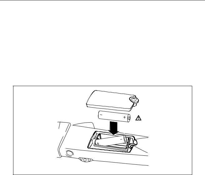
Replacing the Batteries
XWWarning
To avoid false readings, that could lead to possible electric shock or personal injury, replace the batteries as soon as the low battery indicator (B) appears.
Disconnect the test leads before replacing the batteries.
To replace the batteries (refer to Figure 1):
1.Turn the rotary switch to OFF and remove the test leads from the terminals.
2.Loosen the battery compartment door screw, and remove the door from the case bottom.
3.Remove the batteries.
4.Replace the batteries with 2 new AA batteries.
5.Reattach the battery compartment door to the case bottom and tighten the screw.
adc02f.eps
Figure 1. Replacing the Batteries
Cleaning
XW Warning
To avoid electrical shock, remove any input signals before cleaning.
WCaution
To avoid damaging the Meter, do not use aromatic hydrocarbons or chlorinated solvents for cleaning. These solutions will react with the plastics used in the instruments.
Clean the instrument case with a damp cloth and mild detergent.
4
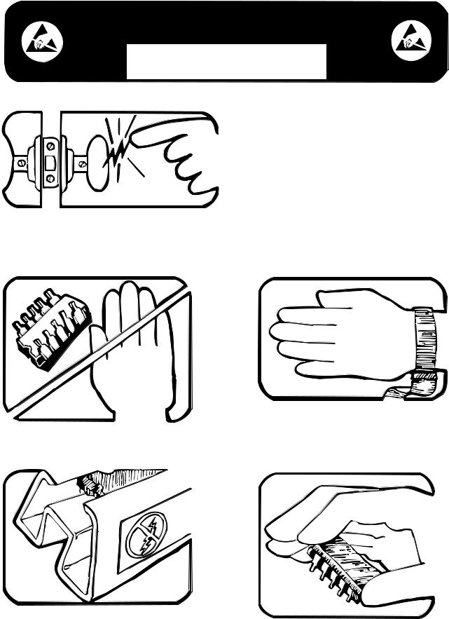
static awareness
A Message From
Fluke Corporation
Some semiconductors and custom IC's can be damaged by electrostatic discharge during handling. This notice explains how you can minimize the chances of destroying such devices by:
1. Knowing that there is a problem.
2. Learning the guidelines for handling them.
3. Using the procedures, packaging, and bench techniques that are recommended.
The following practices should be followed to minimize damage to S.S. (static sensitive) devices.
|
3. DISCHARGE PERSONAL STATIC BEFORE |
|
HANDLING DEVICES. USE A HIGH RESIS- |
1. MINIMIZE HANDLING |
TANCE GROUNDING WRIST STRAP. |
2. KEEP PARTS IN ORIGINAL CONTAINERS |
4. HANDLE S.S. DEVICES BY THE BODY. |
|
UNTIL READY FOR USE. |
||
|

5.USE STATIC SHIELDING CONTAINERS FOR HANDLING AND TRANSPORT.
6.DO NOT SLIDE S.S. DEVICES OVER ANY SURFACE.
7.AVOID PLASTIC,VINYL AND STYROFOAM® IN WORK AREA.
PORTIONS REPRINTED
WITH PERMISSION FROM TEKTRONIX INC.
AND GERNER DYNAMICS, POMONA DIV.
8.WHEN REMOVING PLUG-IN ASSEMBLIES HANDLE ONLY BY NON-CONDUCTIVE EDGES AND NEVER TOUCH OPEN EDGE CONNECTOR EXCEPT AT STATIC-FREE WORK STATION. PLACING SHORTING STRIPS ON EDGE CONNECTOR HELPS PROTECT INSTALLED S.S. DEVICES.
9.HANDLE S.S. DEVICES ONLY AT A STATIC-FREE WORK STATION.
10.ONLY ANTI-STATIC TYPE SOLDERSUCKERS SHOULD BE USED.
11.ONLY GROUNDED-TIP SOLDERING IRONS SHOULD BE USED.
® Dow Chemical
Loading...