


 Loading...
Index 2MF
SpO2 Simulator
Users Manual
PN 3341210 September 2008, Rev. 1
© 2008 Fluke Corporation, All rights reserved. Printed in USA. Specifications subject to change without notice. All product names are trademarks of their respective companies.
Warranty and Product Support
Fluke Biomedical warrants this instrument against defects in materials and workmanship for one full year from the date of original purchase. During the warranty period, we will repair or, at our option, replace at no charge a product that proves to be defective, provided you return the product, shipping prepaid, to Fluke Biomedical. This warranty does not apply if the product has been damaged by accident or misuse or as the result of service or modification by other than Fluke Biomedical. IN NO EVENT SHALL FLUKE BIOMEDICAL BE LIABLE FOR CONSEQUENTIAL DAMAGES.
Only serialized products and their accessory items (those products and items bearing a distinct serial number tag) are covered under this one-year warranty. PHYSICAL DAMAGE CAUSED BY MISUSE OR PHYSICAL ABUSE IS NOT COVERED UNDER THE WARRANTY. Items such as cables and nonserialized modules are not covered under this warranty.
Recalibration of instruments is not covered under the warranty.
This warranty gives you specific legal rights, and you may also have other rights which vary from state to state, province to province, or country to country. This warranty is limited to repairing the instrument to Fluke Biomedical’s specifications.
Warranty Disclaimer
Should you elect to have your instrument serviced and/or calibrated by someone other than Fluke Biomedical, please be advised that the original warranty covering your product becomes void when the tamper-resistant Quality Seal is removed or broken without proper factory authorization. We strongly recommend, therefore, that you send your instrument to Fluke Biomedical for factory service and calibration, especially during the original warranty period.

Notices
All Rights Reserved
♥ Copyright 2008, Fluke Biomedical. No part of this publication may be reproduced, transmitted, transcribed, stored in a retrieval system, or translated into any language without the written permission of Fluke Biomedical.
Copyright Release
Fluke Biomedical agrees to a limited copyright release that allows you to reproduce manuals and other printed materials for use in service training programs and other technical publications. If you would like other reproductions or distributions, submit a written request to Fluke Biomedical.
Unpacking and Inspection
Follow standard receiving practices upon receipt of the instrument. Check the shipping carton for damage. If damage is found, stop unpacking the instrument. Notify the carrier and ask for an agent to be present while the instrument is unpacked. There are no special unpacking instructions, but be careful not to damage the instrument when unpacking it. Inspect the instrument for physical damage such as bent or broken parts, dents, or scratches.
Technical Support
For application support or answers to technical questions, either email techservices@flukebiomedical.com or call 1-800- 850-4608 or 1- 440-248-9300.
Claims
Our routine method of shipment is via common carrier, FOB origin. Upon delivery, if physical damage is found, retain all packing materials in their original condition and contact the carrier immediately to file a claim. If the instrument is delivered in good physical condition but does not operate within specifications, or if there are any other problems not caused by shipping damage, please contact Fluke Biomedical or your local sales representative.
Standard Terms and Conditions
Refunds and Credits
Please note that only serialized products and their accessory items (i.e., products and items bearing a distinct serial number tag) are eligible for partial refund and/or credit. Nonserialized parts and accessory items (e.g., cables, carrying cases, auxiliary modules, etc.) are not eligible for return or refund. Only products returned within 90 days from the date of original purchase are eligible for refund/credit. In order to receive a partial refund/credit of a product purchase price on a serialized product, the product must not have been damaged by the customer or by the carrier chosen by the customer to return the goods, and the product must be returned complete (meaning with all manuals, cables, accessories, etc.) and in “as new” and resalable condition. Products not returned within 90 days of purchase, or products which are not in “as new” and resalable condition, are not eligible for credit return and will be returned to the customer. The Return Procedure (see below) must be followed to assure prompt refund/credit.
Restocking Charges
Products returned within 30 days of original purchase are subject to a minimum restocking fee of 15 %. Products returned in excess of 30 days after purchase, but prior to 90 days, are subject to a minimum restocking fee of 20 %. Additional charges for damage and/or missing parts and accessories will be applied to all returns.

Return Procedure
All items being returned (including all warranty-claim shipments) must be sent freight-prepaid to our factory location. When you return an instrument to Fluke Biomedical, we recommend using United Parcel Service, Federal Express, or Air Parcel Post. We also recommend that you insure your shipment for its actual replacement cost. Fluke Biomedical will not be responsible for lost shipments or instruments that are received in damaged condition due to improper packaging or handling.
Use the original carton and packaging material for shipment. If they are not available, we recommend the following guide for repackaging:
Use a double-walled carton of sufficient strength for the weight being shipped.
Use heavy paper or cardboard to protect all instrument surfaces. Use nonabrasive material around all projecting parts.
Use at least four inches of tightly packed, industry-approved, shock-absorbent material around the instrument.
Returns for partial refund/credit:
Every product returned for refund/credit must be accompanied by a Return Material Authorization (RMA) number, obtained from our Order Entry Group at 1-800- 850-4608 or 1-440-248-9300.
Repair and calibration:
To find the nearest service center, goto www.flukebiomedical.com/service, or
In the U.S.A.:
Cleveland Calibration Lab
Tel: 1-800-850-4606
Email: globalcal@flukebiomedical.com
Everett Calibration Lab
Tel: 1-888-993-5853
Email: service.status@fluke.com
In Europe, Middle East, and Africa:
Eindhoven Calibration Lab
Tel: +31-402-675300
Email: ServiceDesk@fluke.com
In Asia:
Everett Calibration Lab
Tel: +425-446-6945
Email: service.international@fluke.com
Certification
This instrument was thoroughly tested and inspected. It was found to meet Fluke Biomedical’s manufacturing specifications when it was shipped from the factory. Calibration measurements are traceable to the National Institute of Standards and Technology (NIST). Devices for which there are no NIST calibration standards are measured against in-house performance standards using accepted test procedures.
WARNING
Unauthorized user modifications or application beyond the published specifications may result in electrical shock hazards or improper operation. Fluke Biomedical will not be responsible for any injuries sustained due to unauthorized equipment modifications.
Restrictions and Liabilities
Information in this document is subject to change and does not represent a commitment by Fluke Biomedical. Changes made to the information in this document will be incorporated in new editions of the publication. No responsibility is assumed by Fluke Biomedical for the use or reliability of software or equipment that is not supplied by Fluke Biomedical, or by its affiliated dealers.
Manufacturing Location
The Index 2MF Pulse Oximeter Analyzer is manufactured in Everett, Washington by Fluke Biomedical, 6920 Seaway Blvd., Everett, WA, U.S.A.
Table of Contents
Chapter |
Title |
Page |
1 |
Introducing the Index 2MF.................................................................. |
1-1 |
|
Capabilities ........................................................................................................ |
1-1 |
|
Index 2MF Compatibility .................................................................................. |
1-1 |
|
Index 2MF Features ........................................................................................... |
1-2 |
|
Package Contents............................................................................................... |
1-2 |
|
F Version ....................................................................................................... |
1-2 |
|
FE Version..................................................................................................... |
1-2 |
|
Registration Card........................................................................................... |
1-2 |
|
Precautions......................................................................................................... |
1-2 |
|
Electromagnetic Interference and Susceptibility ............................................... |
1-3 |
|
EC EMC Directive 89/336/EEC.................................................................... |
1-3 |
|
EN 50081-1, CLASS A-Emissions ............................................................... |
1-3 |
|
EN 50082-1 Immunity................................................................................... |
1-3 |
|
USA FCC CLASS A ..................................................................................... |
1-3 |
|
Canadian Department of Communications Class A ...................................... |
1-4 |
|
Safety............................................................................................................. |
1-4 |
|
EC Directive 73/23/EEC, Low-Voltage Directive ........................................ |
1-4 |
|
Getting Started ................................................................................................... |
1-4 |
|
Starting the Simulator and Using Menus....................................................... |
1-4 |
|
Using the Optical Finger Probe (All Versions) ............................................. |
1-5 |
2 |
Blood Oxygen and Pulse Oximeters.................................................. |
2-1 |
|
Blood Pressure ................................................................................................... |
2-1 |
|
Gases in Blood ................................................................................................... |
2-1 |
|
Pulse Oximeters ................................................................................................. |
2-2 |
|
How Pulse Oximeters Work.......................................................................... |
2-2 |
|
Spectrophotometry ........................................................................................ |
2-2 |
|
References.......................................................................................................... |
2-4 |
3 |
Index 2MF Overview............................................................................ |
3-1 |
|
The Index 2MF "Finger".................................................................................... |
3-1 |
|
Simulator Electrical Testing (MFE Version only)............................................. |
3-1 |
|
Simulation Settings ............................................................................................ |
3-1 |
|
Running Tests .................................................................................................... |
3-1 |
i

Index 2MF
Users Guide
|
Evaluating Test Results ..................................................................................... |
3-2 |
|
Simulator Functionality ..................................................................................... |
3-2 |
4 |
The Main Menus .................................................................................. |
4-1 |
|
Introduction........................................................................................................ |
4-1 |
|
The Main Menu 1 .............................................................................................. |
4-1 |
|
The Main Menu 2 .............................................................................................. |
4-3 |
5 |
Configuring the Simulator .................................................................. |
5-1 |
|
Configuring for Specific Oximeter Make .......................................................... |
5-1 |
|
Accessing the Make Menu................................................................................. |
5-1 |
|
Verified Oximeter Makes .................................................................................. |
5-2 |
|
R-Curve Specifications ...................................................................................... |
5-2 |
|
Customizing a Make Not Included Within Index 2MF ..................................... |
5-3 |
|
Operation ........................................................................................................... |
5-4 |
6 |
Setting and Changing Simulation Factors ........................................ |
6-1 |
|
About Simulations and Presets .......................................................................... |
6-1 |
|
Setting Simulations ............................................................................................ |
6-1 |
|
The Simulations Menu .................................................................................. |
6-1 |
|
Changing the Default SpO2 Setting .............................................................. |
6-3 |
|
Setting the O2 Saturation Level..................................................................... |
6-3 |
|
Raising or Lowering the Pulse Rate .............................................................. |
6-4 |
|
Returning to Main Menu 1 ............................................................................ |
6-4 |
|
Using Preset Patient Conditions......................................................................... |
6-4 |
|
Setting the Light Artifact ................................................................................... |
6-7 |
|
Setting 02 and Pulse Rate Step Size .................................................................. |
6-8 |
7 |
Testing the Pulse Oximeter Limits..................................................... |
7-1 |
|
Introduction........................................................................................................ |
7-1 |
|
Testing Pulse Oximeter Limits .......................................................................... |
7-1 |
|
Simulating Oxygen Conditions.......................................................................... |
7-1 |
|
Simulating the Pulse Rate .................................................................................. |
7-3 |
|
Simulating Pulse Amplitude .............................................................................. |
7-5 |
|
Simulating Asystole or No Pulse ....................................................................... |
7-7 |
8 |
Using Test Programs .......................................................................... |
8-1 |
|
The AUTO Menus ............................................................................................. |
8-1 |
|
Navigating Through the Programming Process............................................. |
8-1 |
|
The Program Definition Cycle ...................................................................... |
8-2 |
|
The Automatic Test Parameters .................................................................... |
8-2 |
|
Accessing the Autosequences Menu (AUTO)............................................... |
8-3 |
|
Creating a Custom Test Program (Autosequence)............................................. |
8-4 |
|
Selecting a Test Program............................................................................... |
8-5 |
|
Optionally Renaming the Test Program ........................................................ |
8-6 |
|
Configuring the Program............................................................................... |
8-7 |
|
Selecting Print Settings ............................................................................. |
8-8 |
|
Setting the 02 Level .................................................................................. |
8-9 |
|
Setting the Pulse Rate................................................................................ |
8-9 |
|
Setting the Simulation Cycle..................................................................... |
8-10 |
|
Selecting the Make.................................................................................... |
8-10 |
|
Choosing Your Tests................................................................................. |
8-11 |
ii
|
|
|
Contents (continued) |
|
|
|
|
|
|
Selecting Pulse Amplitude ........................................................................ |
8-12 |
|
|
Selecting Motion ....................................................................................... |
8-12 |
|
|
Selecting Presets........................................................................................ |
8-13 |
|
|
Saving Your Program .................................................................................... |
8-13 |
|
Running an Automatic Test Program ................................................................ |
8-14 |
|
|
Returning an Automatic Test Program to Default State .................................... |
8-15 |
|
9 |
Electrical Probe Test........................................................................... |
9-1 |
|
|
Electrical Probe Testing..................................................................................... |
9-1 |
|
|
Probe Test Selection .......................................................................................... |
9-2 |
|
|
|
LED Testing .................................................................................................. |
9-2 |
|
|
Photodiode Test ............................................................................................. |
9-3 |
|
|
Resistance Testing ......................................................................................... |
9-4 |
10 |
Adjusting the LCD Screen .................................................................. |
10-1 |
|
|
Introduction........................................................................................................ |
10-1 |
|
|
LCD Contrast Settings ....................................................................................... |
10-1 |
|
11 |
Manufacturers Mode ........................................................................... |
11-1 |
|
|
Introduction........................................................................................................ |
11-1 |
|
|
Automated Testing............................................................................................. |
11-1 |
|
|
Manufacturer Parameters Available For Simulations........................................ |
11-1 |
|
|
Mathematical Background................................................................................. |
11-2 |
|
|
|
Notes on the Formulas................................................................................... |
11-3 |
|
|
The R-Value Equation................................................................................... |
11-3 |
|
Accessing Manufacturers' Tests......................................................................... |
11-4 |
|
|
|
Setting the Signal Source............................................................................... |
11-4 |
|
|
Setting the R-Value ....................................................................................... |
11-5 |
|
|
Adjusting the Step Amount ........................................................................... |
11-6 |
12 |
Creating Your Own R-Curve............................................................... |
12-1 |
|
|
Introduction........................................................................................................ |
12-1 |
|
|
Generating an R-Curve from a Pulse Oximeter ................................................. |
12-2 |
|
|
Downloading an R-Curve into the Simulator .................................................... |
12-2 |
|
Appendices |
|
||
|
A Printing and Data Transfer .......................................................................... |
A-1 |
|
|
B Error Messages and Corrective Measures ................................................... |
B-1 |
|
|
C |
Accessories List........................................................................................... |
C-1 |
|
D |
Specifications .............................................................................................. |
D-1 |
|
E |
Computer Control........................................................................................ |
E-1 |
|
F Typical Questions and Answers .................................................................. |
F-1 |
|
|
G Custom Probe Test Cables and Electrical Simulation Cables ..................... |
G-1 |
|
|
H |
Glossary....................................................................................................... |
H-1 |
iii

Index 2MF
Users Guide
iv
List of Tables
Table |
Title |
Page |
5-1. Oximeters with Technology Options ..................................................................... |
5-4 |
|
5-2. Oximeters with R-Curve Parameters...................................................................... |
5-4 |
|
6-1. |
Simulations Menu Selections................................................................................. |
6-2 |
6-2. |
Level 0 Presets ....................................................................................................... |
6-5 |
6-3. |
Light Artifacts ........................................................................................................ |
6-7 |
8-1. |
Automatic Test Parameters .................................................................................... |
8-2 |
v

Index 2MF
Users Guide
vi
List of Figures
Figure |
Title |
Page |
|
2-1. |
|
Sphygmomanometer .............................................................................................. |
2-1 |
2-2. Formula for Determining Saturated Oxygen Level................................................ |
2-2 |
||
2-3. Diagram of Sample Finger Probe for a Typical Pulse Oximeter............................ |
2-3 |
||
2-4. Diagram of Light Absorbers in Tissue................................................................... |
2-3 |
||
2-5. |
AC/DC Infrared and Red Absorption Ratio........................................................... |
2-3 |
|
3-1. |
|
Basic Simulator Functions ..................................................................................... |
3-2 |
8-1. |
|
The Program Creation Sequence............................................................................ |
8-2 |
vii

Index 2MF
Users Guide
viii
Chapter 1
Introducing the Index 2MF
Capabilities
The Index 2MF SpO2 Simulator (hereafter the Simulator) allows accurate verification of pulse oximeters by allowing you to test them in a variety of ways. The Simulator provides simulations that allow thorough testing of the complete pulse oximeter, including the optical sensors.
For the first time, there is now a reliable way to gauge the condition and performance of standard pulse oximeters. Fluke Biomedical provided the Simulator to the medical and health industry to allow measuring pulse oximeters currently on the market against widely accepted performance standards.
Using the Simulator as a virtual patient's index finger, you set the the Simulator to simulate a patient with virtually any combination of blood oxygen conditions. When the pulse oximeter under test connects to the Simulator, measure its responses against a set of predetermined readings for a patient with the preset saturation levels and pulse conditions. This procedure matches the pulse oximeter's results against the simulations. Electrically, the Simulator can verify probe diodes, wire continuity, LEDs, and oximeter accuracy.
Like all of Fluke Biomedical's hardware and software systems, the Simulator is backed by Fluke Biomedical's superior support system. If the Simulator ever fails to work perfectly, please refer to the phone, fax, and Internet numbers at front of this book to contact Fluke Biomedical's Technical Support Staff.
Index 2MF Compatibility
The Simulator can quickly establish the state of any given pulse oximeter and determine the performance qualities of the device. The Simulator can test and evaluate most oximeters in the market today.
Because each pulse oximeter manufacturer uses a slightly different technology and algorithm to measure SpO2 (Saturation of Peripheral Oxygen), Fluke Biomedical has preprogrammed into the Simulator a number of different R-values versus SpO2 curves for specific manufacturers. This ensures that the Simulator provides the closest possible simulation. It is also possible to download additional R-value curves directly into the Simulator for non-volatile storage and use. Additionally, the MFE version of the Simulator has adapter cables to test most popular oximeters and probes through electrical simulations.
1-1

Index 2MF
Users Guide
Note
The Simulator is not intended to be a pulse oximeter calibrator.
Index 2MF Features
•Conduct saturated peripheral oxygen (SPO2) simulations with saturation levels between 35% and 100% (in 1% increments)
•Complete probe and electronics assembly testing either optically or electrically (FE version only)
•Probe continuity check (MFE version)
•Variable heart rate settings from 30 beats per minute to 250
•Preset simulations reproduce several patient conditions
•Alarm tests for response time, recovery time, and pulse amplitude
•Portable, weighing in at under 3 pounds, with a 10" x 10" footprint
•Programmable auto sequences
•Computer controllable
•Menu driven with softkey interface and 2-line by 24-character LCD (liquid crystal display) supertwist, alphanumeric display
•Rechargeable lead acid battery, with 8 hours of continuous operation and built-in low battery indicator
Package Contents
The contents of the Simulator package as shipped include:
FVersion
•Index 2MF Pulse Oximeter Tester
•Battery Charger
•User's Guide and Registration Card
FE Version
•Index 2MF Pulse Oximeter Tester
•Battery Charger
•Users Guide and Registration Card
•Ohmeda and Nellcor Probe and Oximeter Adapter (electrical cables)
Registration Card
Once the the Simulator is successfully up and running, complete the postage-paid registration card and mail it to Fluke Biomedical.
Precautions
Observe these precautions when using the Simulator; like any electronic equipment, it should be adequately protected both when moving and in storage.
W Caution
When connecting the Simulator to a peripheral, such as a PC’s RS232 serial port or printer, power OFF both the Simulator and the peripheral device during connection and disconnection.
Failure to follow this precaution may result in damage to the equipment.
1-2
Introducing the Index 2MF |
1 |
Electromagnetic Interference and Susceptibility |
The Simulator battery life can be seriously shortened by leaving the instrument turned on for many hours after the low battery alarm sounds. To avoid damage:
•Package and handle the Simulator to ensure that the power switch cannot accidentally turn on during shipment.
•Always connect the Simulator to its charger when not in use. The Simulator allows continuous charging, a practice that ensures full power charge whenever needed. The Simulator may also be used while charging.
•Always turn off the Simulator and connect it to its charger when the low battery alarm sounds. The Simulator can be used within about 1 minute of commencing charge. The Simulator picks up two or more hours of battery run-time for each hour of charger connect time, even when running with the charger connected.
•Avoid placing the Simulator in contact with, or in close proximity to, Electrosurgery units (ESUs), MRIs, and defibrillators.
•Only use an appropriately rated battery charger to avoid damage to the Simulator’s battery. Based on the testing below, the Simulator bears the CE mark.
Electromagnetic Interference and Susceptibility
EC EMC Directive 89/336/EEC
EN 50081-1, CLASS A-Emissions
The Simulator has been type tested by an independent testing laboratory and found to meet the requirements of EC Directive 89/336/EEC for Radiated Emissions and Line Conducted Emissions. Verification was to the limits and methods of EN 55011. The device is classified as EN 55011, Group 1, Class A.
EN 50082-1 Immunity
The Simulator was also tested and found to meet requirements for Electrostatic Discharge Susceptibility, Radiated Susceptibility, and Electrical Fast Transient/Burst Susceptibility. Verification of compliance was conducted to the limits and methods of EN 50082- 1:1992, IEC 801-2, IEC 801-3, and IEC 801-4.
Note
If using a battery charger while the Simulator is in the Electrical Simulation Mode, the user may observe a spike in the voltage on the line to the battery charger, thereby producing erratic results. If you suspect this has occurred, retest the oximeter with the battery charger disconnected.
USA FCC CLASS A
This equipment has been tested and found to comply with the limits for a Class A digital device, pursuant to Part 15 of the FCC Rules.
These limits provide reasonable protection against harmful interference when operating the equipment in a commercial environment. Like similar medical equipment, this
1-3

Index 2MF
Users Guide
equipment generates, uses, and can radiate radio frequency energy and, if not installed and used in accordance with the instruction manual, may cause harmful interference to radio communications. Operation of this equipment in a residential area could cause interference, in which case the user will be required to correct the interference.
Canadian Department of Communications Class A
This digital apparatus does not exceed Class A limits for radio emissions from digital apparatus set out in the Radio Interference Regulations of the Canadian Department of Communications.
Le present appareil numerique n'met pas du bruits radioelectriques depassant les limites applicables aux appareils numerique de la Class A prescrites dans le Reglement sur le brouillage radioelectrique edicte par le ministere des Communications du Canada.
Note
The Simulator, like many pulse oximeters, may have its operation affected by strong electromagnetic sources, such as electrosurgery equipment. It may also be affected by imaging equipment, such as Magnetic Resonance Imaging (MRI). It is the user’s responsibility to verify performance of the Simulator prior to use in these kinds of environments.
Safety
The Simulator is a battery-powered device which operates at voltages that are considered intrinsically safe. Independent laboratory approval to a test standard is thus not required. The battery charger used must meet the safety requirements for your country.
EC Directive 73/23/EEC, Low-Voltage Directive
The Simulator operates below 75 VDC, thus EN 61010-1 is not applicable.
Getting Started
Unpack the Simulator from the shipping carton. Check that the shipment is complete and all parts are intact.
Starting the Simulator and Using Menus
Slide the power switch to the "I" (on) position to power up the system. The LCD sequentially displays the following screens for about two seconds each before ending on the Main Menu 1 screen:
•Bio-Tek Instruments Inc. with model number and version
•Software version number and copyright years
•Make of last selected R-curve
•Main Menu 1 screen
esl001.eps
1-4

Introducing the Index 2MF |
1 |
Getting Started |
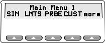
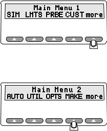
When the Main Menu 1 displays in the LCD, the following options are available:
esl002.eps
The Main Menu 1 consists of the primary test functions available to the Simulator, with the softkeys SIM, LMTS, PRBE, CUST, and more. Press the up arrow below the menu item to select a menu option, change a setting, or to advance to additional menus.
Note
If you see a message warning you that your battery is low, you need to attach the battery charger. Call Fluke Biomedical for assistance if needed.
Toggle between Main Menu 1 and Main Menu 2 with the more softkey. For example, you have these options at the Main Menu 1 screen:
Press the softkey SIM, and then MAN to open the Simulations menu. The menu “Simulations:” appears in the Simulator LCD. This menu allows you to set oxygen saturation levels and heart rate in beats-per-minute (BPM).
Press the softkey MAN to set the Sp02 levels from 35 to 100%, and the heart rate from 25 to 250 BPM.
1.The LCD indicates current Sp02 level and BPM. Additional softkey options now available allow you to set the SpO2 levels (02+ and 02-), as well as increase and decrease the BPM (BPM+ and BPM-).
Return to the previous menu, Main Menu 1, by pressing the esc softkey. For detailed information on using the test features, refer to the relevant chapter in this users guide.
Using the Optical Finger Probe (All Versions)
Connect the finger probe of the pulse oximeter under test to the Simulator finger probe attachment. Position the pulse oximeter LEDs on the bottom of the Simulator finger probe attachment.
From the Main Menu 1, select the SpO2 and Heart Rate settings by pressing the appropriate + or - (plus or minus) keys, and viewing the settings displayed on the the Simulator LCD.
Note
Oximeters take from 5 to 20 pulses to respond to a change in simulated
SpO2 or BPM.
1-5

Index 2MF
Users Guide
1-6

Chapter 2
Blood Oxygen and Pulse Oximeters
Blood Pressure
Blood pressure readings provide valuable information about the condition of our bodies, indicating health or the lack of it. As the heart contracts (systole) and relaxes (diastole), the volume of freshly-oxygenated blood increases and decreases measurably within the artery walls. This action causes the artery walls to expand and contract in rhythm with the heart. The force of the blood exerted upon the artery walls is what is called blood pressure. Contraction produces the highest pressure, and relaxation the lowest.
A sphygmomanometer (shown in Figure 2-1) is one tool for measuring blood pressure. When our blood pressure is taken, it is measured at the brachial artery in the forearm in millimeters of mercury (mmHg). If our blood pressure reading is at or near 120 mmHg (systolic) over 80 mmHg (diastolic), we are considered to be in peak health, all else being normal.
esl003.eps
Figure 2-1. Sphygmomanometer
Gases in Blood
Blood pressure is not the whole story, however, since the exact concentration of gases such as carbon dioxide and especially oxygen in your blood cannot be determined by a simple blood pressure test.
To determine gas concentrations accurately, specifically saturated oxygen, a blood-gas sensing device must be used, and must be capable of detecting the wide range of nominal values for these gases. Gas concentrations in blood, specifically oxygen (O2) and carbon
2-1

Index 2MF
Users Guide
dioxide (CO2), can be expressed as milliliters of gas per liter of blood, and can be indicated by the partial pressure that the gases exert in your blood at a given temperature.
Pulse Oximeters
Because of their ease of use in many hospitaland critical-care situations, pulse oximeters have greatly increased in popularity since their introduction. Today, pulse oximeters are virtually required equipment in situations where the monitoring of arterial oxygen saturation (SaO2) is essential, such as when anesthesia is in use, both during an operation and in post-operative recovery, intensive care, transport, and patient home care.
Pulse oximeters have proven to be capable and reliable, being highly accurate in measuring blood SaO2 in the range of 80-100%, while at the same time needing little, if any, calibration. No patient preparation is required before using the pulse oximeter; in addition, the devices are so simple to operate that specialized training is unnecessary.
How Pulse Oximeters Work
Pulse oximeters are defined as non-invasive, arterial, oxygen-saturation monitors which measure the ratio of two principal forms of hemoglobin in the blood: saturated arterial hemoglobin (also called oxyhemoglobin), HbO2/SAT, to unsaturated (or reduced) hemoglobin, Hb.
The arterial oxygen saturation, SaO2, is defined as the ratio of the concentration of oxyhemoglobin (cHbO2) to the concentration of HbO2 + Hb (cHbO2 + cHb). Oxygen saturation is commonly expressed as a percentage and is calculated according to the formula in Figure 2-2.
esl004.eps
Figure 2-2. Formula for Determining Saturated Oxygen Level
Using this information, a correctly calibrated and operating pulse oximeter can accurately predict the level of oxygen in the blood, which in turn provides valuable data about the health of a patient, and in the case of anesthesia and post-operative recovery, the status of the patient.
Spectrophotometry
Pulse oximeters operate on the principle known as spectrophotometry, using wavelengths of light to determine the concentration of oxygen in the blood. Because we already know the wavelengths for the light absorption of blood hemoglobin, we can mathematically determine the arterial oxygen saturation in a patient's blood.
The light emitting diodes (LED's) of a pulse oximeters shine two types of light—near infrared light (at 940 nanometers) and red light (at 660 nanometers)—wavelengths that pass through the skin and which are absorbed by both the oxyhemoglobin and the reduced hemoglobin. These light beams pass through the index finger of a patient to photo detectors on the opposite side of the pulse oximeter.
2-2

Blood Oxygen and Pulse Oximeters |
2 |
Pulse Oximeters |
Figure 2-3 shows a typical pulse oximeter configuration, noting the location of the red and infrared LED's.
940nm Infrared LED

 660nm Red LED
Photosensor
esl005.eps
Figure 2-3. Diagram of Sample Finger Probe for a Typical Pulse Oximeter
Using this dual light emitting and sensing technology, the pulse oximeter determines the amount of light absorbed by the blood and calculates the percent of oxygen saturation (SaO2).
However, it is not quite that simple. Pulse oximeters must also calculate out the effect of absorption caused by the presence of venous and capillary blood and soft tissue in order to obtain the true SaO2 value. To do so, pulse oximeters use a system that distinguishes between “AC" components (the pulsating arterial blood) and “DC" components (the non- pulsating components mentioned just above).
Figure 2-4 shows the different AC and DC components graphically.
AC |
Absorption due to pulse |
|
Capillary blood |
Light |
|
Absorption |
|
DC |
|
esl006.eps
Figure 2-4. Diagram of Light Absorbers in Tissue
The pulse oximeter determines the AC component of absorbency at each wavelength and divides this by the corresponding DC (amplitude) component. This results in a "pulseadded" absorbency that is independent of the light intensity. The ratio (R) of these pulseadded absorbances is calculated using the formula shown in Figure 2-5.
esl007.eps
Figure 2-5. AC/DC Infrared and Red Absorption Ratio
When the ratio of red-to-infrared absorbance equals 1.00, the saturation is approximately 81%.
2-3

Index 2MF
Users Guide
References
•Accuracy and Precision of Fourteen Pulse Oximeters, B. Hannhart, et al, Neonatal Intensive Care, Nov./Dec. 1991.
•Clinical Pulse Oximetry, Thomas L. Petty, MD, Anesthesiology, v. 70, no. 1, Jan. 1989.
•Oximetry/Blood Gas, --- , Medical Electronics, Oct. 1989.
•The Concise Columbia Encyclopedia, (Columbia University Press, 1991), Microsoft Bookshelf, 1992.
2-4
Chapter 3
Index 2MF Overview
The Index 2MF "Finger"
The Simulator system has a patented optical “finger” that takes the place of an actual patient's index finger. This finger works with any pulse oximeter that detects SpO2 (Saturation of Peripheral Oxygen) through the index finger (as opposed to the earlobe or toe) tissue.
Inserting the Index finger into the pulse oximeter probe effectively connects the two devices for testing purposes.
Note
When connecting a finger sensor, onto the Simulator's “finger,” make sure that the red LEDs (light emitting diodes) are on the bottom and that the pulse oximeter fingertip sensor is on as far as possible.
Simulator Electrical Testing (MFE Version only)
Electrical testing of oximeters is similar to optical testing. However, all electrical testing simulations are output through the electrical port on the back of the Simulator, thus eliminating the probe from the circuit. FBC makes specific cables to connect the electrical port on the Simulator to oximeter port for electrical testing. Check FBC website or price list for details about these specific cables. A separate probe check is performed via the probe port on the back of the unit that analyzes LEDs, photodiodes, and wire resistance for potential problems.
Simulation Settings
Once connected, the Simulator can simulate virtually any patient condition, with programmable SpO2 ranges from 35% to 100%, pulse rates from 30 BPM to 250 BPM, and an amplitude factor (non-pulsatile components such as soft tissue and venous blood, also called the DC component) of 0% to 20%.
Running Tests
The Simulator runs through a series of simulations to test the sensitivity and performance limits of the pulse oximeter in question. You can run one test or a series of tests, with
3-1
Index 2MF
Users Guide
stable or fluctuating oxygen and pulse levels. You can even connect the Simulator to a computer to control the Simulator and run all tests.
Evaluating Test Results
The Simulator is what may be called a "Transfer Standard.” Such a standard lets you take measurements on an unknown device, and see how closely it compares to a known device measured with the same transfer standard (or an identical one).
Fluke Biomedical has measured the operational characteristics of different makes of oximeters, all believed to be properly calibrated and operating correctly. Users access these measurements when selecting an oximeter make for testing.
For a Transfer Standard such as the Simulator, simulating devices which have readout resolutions of 1 % (oximeters) or repeatability of simulations better than 1 % is mandatory. The Simulator repeatability is conservatively specified at better than +1 standard deviation.
In Fluke Biomedical's experience with oximeters characterized by make, oximeters track the SpO2 simulations typically within 1 % to 2 % from 100 % - 60 %. Below 60 %, many pulse oximeters have unspecified accuracies; results can vary widely. That means, for example, that if you have set up a simulation of 92 %, you can expect your oximeter to read 92 %, ±1 %.
Print results for study and archiving purposes directly from the Simulator via the built-in serial RS-232 port or the Centronics parallel printer port. Results can also be sent over a serial cable directly to a computer, for onscreen evaluation or storage in a database.
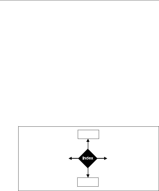
Simulator Functionality
Figure 3-1 illustrates the basic functions of the Simulator system.
Manual
Testing
Control by |
|
Automatic |
Computer |
|
Testing |
|
|
|
Result
esl008.eps
Figure 3-1. Basic Simulator Functions
3-2
Chapter 4
The Main Menus
Introduction
When you first turn on the Simulator, it sequentially displays the following screens for about one second each before ending with the Main Menu 1 screen:
•Bio-Tek Instruments Inc. and model number and version
•Software version number and copyright years
•Make of last selected R-curve
esl009.eps
Note
If at power-up, the batteries are low and in need of recharging, the message “WARNING! BATTERY LOW!” appears on the LCD.
The Main Menu 1
The Main Menu 1 choices give you access to the full Simulator system. This section explains each softkey and its associated menu choices.
Note
Pressing the esc softkey (visible in many menu screens) returns you to a previous menu. Pressing more, when visible, toggles between menus.
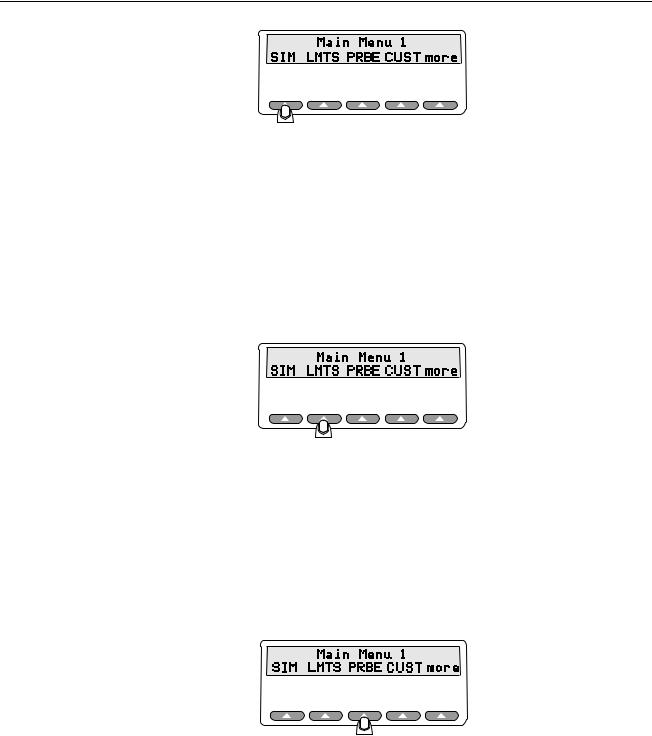
SIM lets you set oxygen saturation levels and heart rates (BPM.)
4-1
Index 2MF
Users Guide
fgg010.eps
Selecting SIM opens the menu displaying the following:
•MAN to run manual simulations
•PRESET to run factory-defined simulations
•AMB to set ambient light levels
•CUST to create custom makes
•esc softkey to return to Main Menu 1
LMTS lets you set the alarm limits for oxygen, beats per minute, pulse amplitude, and lets you set up a timer for asystole.
fgg011.eps
Selecting LMTS opens the menu displaying the following:
•O2 to set up Sp02 alarm limits level and response time
•BPM to set up rate alarm limits and response time
•AMP to select pulse amplitude limits
•ASYS to set up asystole
PRBE offers the electrical probe test menu to analyze oximeter probe integrity. Tests include LED voltages, photo diode results, and pin-to-pin resistance.
fgg012.eps
Selecting PRBE tests attached probes and displays the following options:
•LEDS to view the red and infrared LEDs
•PHTO to view photo diode results
•RES to view pin-to-pin resistance
•REDO (requires an attached probe)
•esc softkey to return to Main Menu 1
4-2
The Main Menus 4
The Main Menu 2
fgg013.eps
The CUST menu options are for creating custom makes by choosing a light technology and R-Curve. This custom make can be stored for later use. Custom makes are used when the pulse oximeter being tested is not in the factory preset makes.
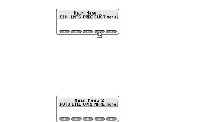
The Main Menu 2
The softkey more toggles between Main Menu 1 and Main Menu 2. Main Menu 2 allows you to select a pulse oximeter type by make, configure the Simulator serial (RS232) port, and adjust the contrast of the LCD screen.
fgg161.eps
The choices available at the Main Menu 2 include:
•AUTO to create and run tailored test procedures
•UTIL to change the display and configure the RS232
•OPTS to open the Advanced Options menu
•MAKE to select the pulse oximeter being tested
•more to toggle Main Menu 1
Each of these Main Menu choices is discussed separately in the next few chapters.
Note
Pressing esc at any point within the Simulator will always return you to any previous menu, until you have returned to Main Menu 1 or 2.
4-3

Index 2MF
Users Guide
4-4
Chapter 5
Configuring the Simulator
Configuring for Specific Oximeter Make
Light technology and R-Curve data must be known in order to test a pulse oximeter, optically via finger or electrically. You can configure the Simulator to match the make of pulse oximeter(s) you will be testing. The Simulator stores the definitions for different makes of pulse oximeters. You can change variables for each of the pulse oximeter types to match the devices you will be testing.
Accessing the Make Menu
Change the make of the pulse oximeter stored in the Simulator's memory using the Make menu.
1. To get to the Make menu, press more from Main Menu 1.
fgg014.eps
2. You will then see the screen for the Main Menu 2. Press the softkey MAKE.
fgg169.eps
5-1
Index 2MF
Users Manual
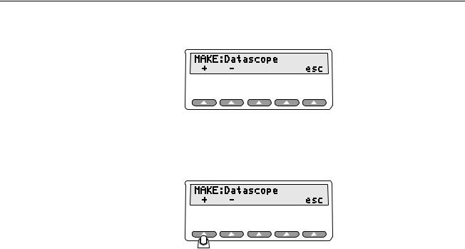
You will see the following appear in the Simulator's LCD display:
esl016.eps
3.Press the softkey for the + or - to scroll through the Simulator's pre-programmed pulse oximeter makes and models. In the screen that follows, the selected make is the Datascope.
esl017.eps
4.To return to Main Menu 2, press esc.
5.Then, to return to Main Menu 1, press the softkey more.
Verified Oximeter Makes
The following makes of oximeters have been verified as working properly, both electronically and with their probes, and are pre-programmed into the Simulator:
•BCI® (3101)
•Criticare® (504)
•Datascope® (Passport)
•Datex® (CardioCap, Ultima, Satellite Trans, AS/3, 251)
•HP® (Merlin)
•Masimo®
•Nellcor® (N-100, 200)
•Nihon-Kohden® (Lifescope)
•Ohmeda® (3700) and Nova
•Respironics®
R-Curve Specifications
Fluke Biomedical, in cooperation with the manufacturers, developed the R-Curves for the devices listed previously.
5-2
Loading...