


725
Table of contents
 Loading...
725
Multifunction Process Calibrator
®
October, 1998 Rev.3, 5/04
© 1998-2004 Fluke Corporation, All rights reserved.
All product names are trademarks of their respective companies.
Users Manual

LIMITED WARRANTY AND LIMITATION OF LIABILITY
Each Fluke product is warranted to be free from defects in material and workmanship under normal use and service. The warranty period is three years and
begins on the date of shipment. Parts, product repairs, and services are warranted for 90 days. This warranty extends only to the original buyer or end-user
customer of a Fluke authorized reseller, and does not apply to fuses, disposable batteries, or to any product which, in Fluke’s opinion, has been misused, altered,
neglected, contaminated, or damaged by accident or abnormal conditions of operation or handling. Fluke warrants that software will operate substantially in
accordance with its functional specifications for 90 days and that it has been properly recorded on non-defective media. Fluke does not warrant that software will
be error free or operate without interruption.
Fluke authorized resellers shall extend this warranty on new and unused products to end-user customers only but have no authority to extend a greater or different
warranty on behalf of Fluke. Warranty support is available only if product is purchased through a Fluke authorized sales outlet or Buyer has paid the applicable
international price. Fluke reserves the right to invoice Buyer for importation costs of repair/replacement parts when product purchased in one country is submitted
for repair in another country.
Fluke’s warranty obligation is limited, at Fluke’s option, to refund of the purchase price, free of charge repair, or replacement of a defective product which is
returned to a Fluke authorized service center within the warranty period.
To obtain warranty service, contact your nearest Fluke authorized service center to obtain return authorization information, then send the product to that service
center, with a description of the difficulty, postage and insurance prepaid (FOB Destination). Fluke assumes no risk for damage in transit. Following warranty
repair, the product will be returned to Buyer, transportation prepaid (FOB Destination). If Fluke determines that failure was caused by neglect, misuse,
contamination, alteration, accident, or abnormal condition of operation or handling, including overvoltage failures caused by use outside the product’s specified
rating, or normal wear and tear of mechanical components, Fluke will provide an estimate of repair costs and obtain authorization before commencing the work.
Following repair, the product will be returned to the Buyer transportation prepaid and the Buyer will be billed for the repair and return transportation charges (FOB
Shipping Point).
THIS WARRANTY IS BUYER'S SOLE AND EXCLUSIVE REMEDY AND IS IN LIEU OF ALL OTHER WARRANTIES, EXPRESS OR IMPLIED, INCLUDING BUT
NOT LIMITED TO ANY IMPLIED WARRANTY OF MERCHANTABILITY OR FITNESS FOR A PARTICULAR PURPOSE. FLUKE SHALL NOT BE LIABLE FOR
ANY SPECIAL, INDIRECT, INCIDENTAL OR CONSEQUENTIAL DAMAGES OR LOSSES, INCLUDING LOSS OF DATA, ARISING FROM ANY CAUSE OR
THEORY.
Since some countries or states do not allow limitation of the term of an implied warranty, or exclusion or limitation of incidental or consequential damages, the
limitations and exclusions of this warranty may not apply to every buyer. If any provision of this Warranty is held invalid or unenforceable by a court or other
decision-maker of competent jurisdiction, such holding will not affect the validity or enforceability of any other provision.
11/99
Fluke Corporation
P.O. Box 9090
Everett, WA 98206-9090
U.S.A.
Fluke Europe B.V.
P.O. Box 1186
5602 BD Eindhoven
The Netherlands

Table of Contents
Title Page
Introduction....................................................................................................................1
Contacting Fluke............................................................................................................ 1
Standard Equipment...................................................................................................... 3
Safety Information.......................................................................................................... 3
Getting Acquainted with the Calibrator .......................................................................... 8
Input and Output Terminals ...................................................................................... 8
Keys.......................................................................................................................... 10
Display ...................................................................................................................... 13
Getting Started .............................................................................................................. 14
Shut Down Mode ........................................................................................................... 14
Contrast Adjustment ...................................................................................................... 16
Using Measure Mode..................................................................................................... 17
Measuring Electrical Parameters (Upper Display).................................................... 17
Current Measurement with Loop Power.................................................................... 17
Measuring Electrical Parameters (Lower Display).................................................... 19
Measuring Temperature............................................................................................ 20
i

725
Users Manual
Using Thermocouples........................................................................................... 20
Using Resistance-Temperature Detectors (RTDs) ............................................... 23
Measuring Pressure .................................................................................................. 26
Zeroing with Absolute Pressure Modules.................................................................. 27
Using Source Mode........................................................................................................ 29
Sourcing 4 to 20 mA.................................................................................................. 29
Simulating a 4- to 20-mA Transmitter........................................................................ 29
Sourcing Other Electrical Parameters ....................................................................... 29
Simulating Thermocouples........................................................................................ 32
Simulating RTDs........................................................................................................ 32
Sourcing Pressure..................................................................................................... 35
Setting 0 % and 100 % Output Parameters ................................................................... 37
Stepping and Ramping the Output................................................................................. 37
Manually Stepping the mA Output............................................................................. 37
Auto Ramping the Output.......................................................................................... 38
Storing and Recalling Setups......................................................................................... 38
Calibrating a Transmitter................................................................................................ 39
Calibrating a Pressure Transmitter................................................................................. 41
Calibrating an I/P Device................................................................................................ 43
Testing an Output Device............................................................................................... 45
Remote Control Commands........................................................................................... 46
Replacing the Batteries.................................................................................................. 49
Replacing the Fuses ...................................................................................................... 49
Maintenance................................................................................................................... 50
Cleaning the Calibrator.............................................................................................. 50
Service Center Calibration or Repair......................................................................... 50
Replacement Parts.................................................................................................... 51
Accessories.................................................................................................................... 53
ii

Contents (continued)
External Fluke Pressure Module Compatibility ......................................................... 53
Specifications................................................................................................................. 56
DC Voltage Measurement......................................................................................... 56
DC Voltage Source ................................................................................................... 56
Millivolt Measurement and Source*........................................................................... 56
DC mA Measurement and Source............................................................................ 57
Ohms Measurement.................................................................................................. 57
Ohms Source............................................................................................................ 57
Frequency Measurement.......................................................................................... 57
Frequency Source..................................................................................................... 58
Temperature, Thermocouples................................................................................... 58
Loop Power Supply................................................................................................... 59
RTD Excitation (simulation) ...................................................................................... 59
Temperature, RTD Ranges, and Accuracies (ITS-90).............................................. 59
Pressure Measurement............................................................................................. 60
General Specifications.............................................................................................. 60
iii

725
Users Manual
iv

List of Tables
Table Title Page
1. Summary of Source and Measure Functions........................................................................ 2
2. International Symbols ........................................................................................................... 7
3. Input/Output Terminals and Connectors............................................................................... 9
4. Key Functions....................................................................................................................... 11
5. Thermocouple Types Accepted ............................................................................................ 21
6. RTD Types Accepted............................................................................................................24
7. mA Step Values.................................................................................................................... 38
8A. Remote Control Upper Display ............................................................................................. 46
8B. Remote Control Lower Display ............................................................................................. 46
8C. "S" Commands Select Sensor Type ..................................................................................... 48
9. Replacement Parts ............................................................................................................... 51
10. Fluke Pressure Module Compatibility ................................................................................... 53
11. Pressure Modules................................................................................................................. 54
v

725
Users Manual
vi

List of Figures
Figure Title Page
1. Standard Equipment............................................................................................................. 6
2. Input/Output Terminals and Connectors............................................................................... 8
3. Keys...................................................................................................................................... 10
4. Elements of a Typical Display............................................................................................... 13
5. Voltage-to-Voltage Test........................................................................................................ 15
6. Adjusting the Contrast .......................................................................................................... 16
7. Measuring Voltage and Current Output ................................................................................ 17
8. Connections for Supplying Loop Power................................................................................ 18
9. Measuring Electrical Parameters.......................................................................................... 19
10. Measuring Temperature with a Thermocouple ..................................................................... 22
11. Measuring Temperature with an RTD, Measuring 2-, 3-, and 4-Wire Resistance ................ 25
12. Gage and Differential Pressure Modules.............................................................................. 26
13. Connections for Measuring Pressure.................................................................................... 28
14. Connections for Simulating a 4- to 20-mA Transmitter......................................................... 30
15. Electrical Sourcing Connections........................................................................................... 31
16. Connections for Simulating a Thermocouple........................................................................ 33
17. Connection for Simulating a 3-Wire RTD.............................................................................. 34
vii

725
Users Manual
18. Connections for Sourcing Pressure....................................................................................... 36
19. Calibrating a Thermocouple Transmitter............................................................................... 40
20. Calibrating a Pressure-to-Current (P/I) Transmitter............................................................... 42
21. Calibrating a Current-to-Pressure (I/P) Transmitter............................................................... 44
22. Calibrating a Chart Recorder.................................................................................................45
23. Replacing the Battteries ........................................................................................................ 50
24. Replacement Parts................................................................................................................ 52
viii

Multifunction Process Calibrator
Introduction
Your Fluke 725 Multifunction Process Calibrator (referred
to as “the calibrator”) is a handheld, battery-operated
instrument that measures and sources electrical and
physical parameters. See Table 1.
In addition to the functions in Table 1, the calibrator has
the following features and functions:
• A split-screen display. The upper display allows you
to measure volts, current, and pressure only. The
lower display allows you to measure and source
volts, current, pressure, resistance temperature
detectors, thermocouples, frequency, and ohms.
• Calibrates a transmitter using the split-screen.
• A thermocouple (TC) input/output terminal and
internal isothermal block with automatic referencejunction temperature compensation.
• Stores and recalls setups.
• Manual stepping and automatic stepping and
ramping.
• Controls the calibrator remotely from a PC running a
terminal emulator program.
Contacting Fluke
To order accessories, receive operating assistance, or
get the location of the nearest Fluke distributor or Service
Center, call:
USA: 1-888-99-FLUKE (1-888-993-5853)
Canada: 1-800-36-FLUKE (1-800-363-5853)
Europe: +31 402-675-200
Japan: +81-3-3434-0181
Singapore: +65-738-5655
Anywhere in the world: +1-425-446-5500
Or, visit Fluke's Web site at www.fluke.com.
1
725
Users Manual
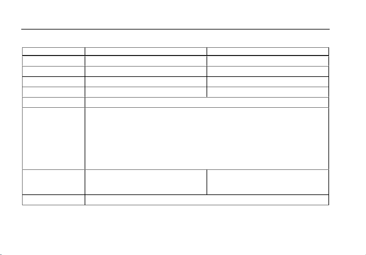
Table 1. Summary of Source and Measure Functions
Function Measure Source
dc V 0 V to 30 V 0 V to 10 V
dc mA 0 to 24 mA 0 to 24 mA
Frequency 1 CPM to 10 kHz 1 CPM to 10 kHz
Resistance 0 Ω to 3200 Ω 15 Ω to 3200 Ω
Thermocouple Types E, J, K, T, B, R, S, L, U, N, mV
RTD
(ResistanceTemperature
Detector)
Pressure 27 modules ranging from 10 in. H2O to
10,000 psi
Other functions Loop supply, Step, Ramp, Memory, Dual display
Pt100 Ω (385)
Pt100 Ω (3926)
Pt100 Ω (3916)
Pt200 Ω (385)
Pt500 Ω (385)
Pt1000 Ω (385)
Ni120
27 modules ranging from 10 in. H2O to
10,000 psi using an external pressure source
(hand pump)
2

Standard Equipment
Standard Equipment
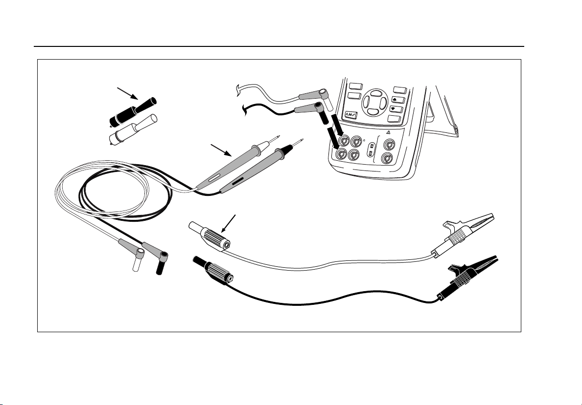
The items listed below and shown in Figure 1 are included
with your calibrator. If the calibrator is damaged or
something is missing, contact the place of purchase
immediately. To order replacement parts or spares, see
the user-replaceable parts list in Table 9.
• TL75 test leads (one set)
• AC70A alligator clips (one set)
• Stackable alligator clip test leads (one set)
• 725 Product Overview Manual
• 725 CD-ROM (contains Users Manual)
• Spare fuse
Safety Information
The calibrator is designed in accordance with IEC1010-1,
ANSI/ISA S82.01-1994 and CAN/CSA C22.2 No. 1010.1-
92. Use the calibrator only as specified in this manual,
otherwise the protection provided by the calibrator may be
impaired.
A Warning identifies conditions and actions that pose
hazard(s) to the user; a Caution identifies conditions and
actions that may damage the calibrator or the equipment
under test.
International symbols used on the calibrator and in this
manual are explained in Table 2.
3

725
Users Manual
W Warning
To avoid possible electric shock or personal injury:
• Do not apply more than the rated voltage, as marked on the calibrator, between the terminals, or
between any terminal and earth ground (30 V 24 mA max all terminals).
• Before each use, verify the calibrator’s operation by measuring a known voltage.
• Follow all equipment safety procedures.
• Never touch the probe to a voltage source when the test leads are plugged into the current terminals.
• Do not use the calibrator if it is damaged. Before you use the calibrator, inspect the case. Look for
cracks or missing plastic. Pay particular attention to the insulation surrounding the connectors.
• Select the proper function and range for your measurement.
• Make sure the battery door is closed and latched before you operate the calibrator.
• Remove test leads from the calibrator before you open the battery door.
• Inspect the test leads for damaged insulation or exposed metal. Check test leads continuity. Replace
damaged test leads before you use the calibrator.
• When using the probes, keep your fingers away from the probe contacts. Keep your fingers behind the
finger guards on the probes.
• Connect the common test lead before you connect the live test lead. When you disconnect test leads,
disconnect the live test lead first.
• Do not use the calibrator if it operates abnormally. Protection may be impaired. When in doubt, have the
calibrator serviced.
• Do not operate the calibrator around explosive gas, vapor, or dust.
4

Safety Information
W Warning
• When using a pressure module, make sure the process pressure line is shut off and depressurized
before you connect it or disconnect it from the pressure module.
• Use only 4 AA batteries, properly installed in the calibrator case, to power the calibrator.
• Disconnect test leads before changing to another measure or source function.
• When servicing the calibrator, use only specified replacement parts.
• To avoid false readings, which could lead to possible electric shock or personal injury, replace the
battery as soon as the battery indicator (M) appears.
Caution
To avoid possible damage to calibrator or to equipment under test:
• Disconnect the power and discharge all high-voltage capacitors before testing resistance or continuity.
• Use the proper jacks, function, and range for your measurement or sourcing application.
5
725
Users Manual
AC72
Alligator Clips
Test Lead Set
TL75
m
4
W
Stackable
Test Leads
Figure 1. Standard Equipment
STORE
SETUP
RECALL
3
0
V
M
A
X
A
L
S
O
U
R
C
E
/ M
E
A
S
U
R
E
m
+
A
V
3
W
H
z
R
T
D
-
A
C
O
M
100%
25%
25%
0%
L
T
E
R
M
I
N
A
L
S
M
E
A
S
U
R
E
V
T
C
m
A
L
O
O
P
C
O
M
sh01f.eps
6
Safety Information
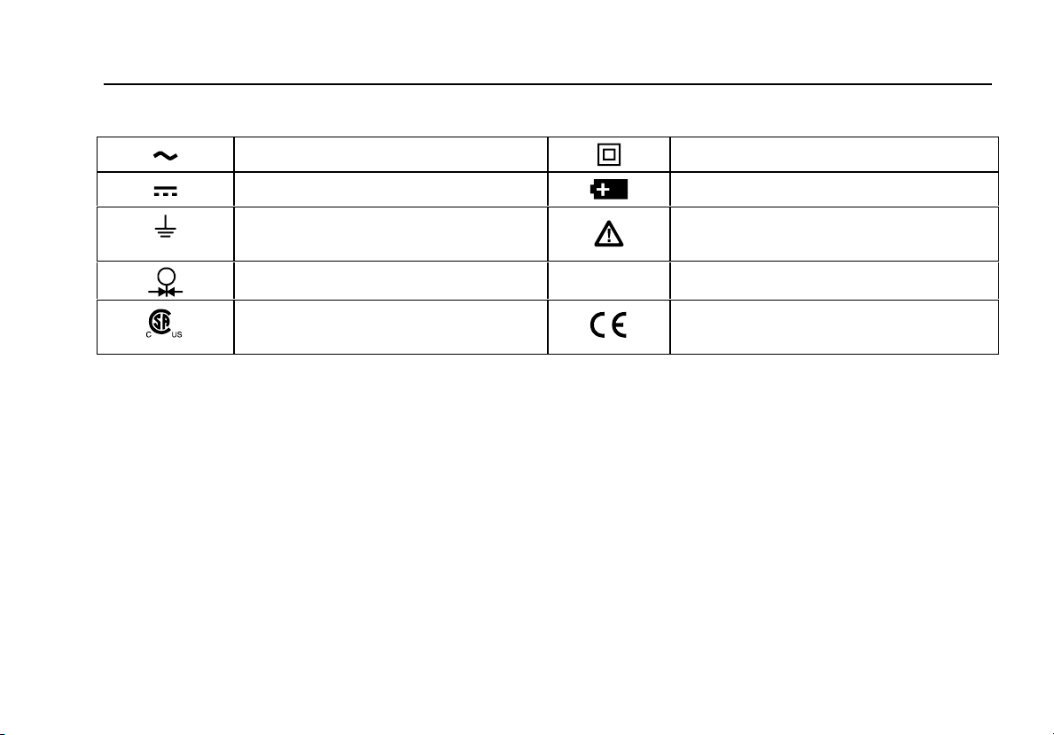
Table 2. International Symbols
AC - Alternating current Double insulated
DC - Direct current Battery
Earth ground Refer to the manual for information about
this feature.
Pressure
Conforms to Canadian Standards
Association directives
O
ON/OFF
Conforms to European Union directives
7
725
Users Manual
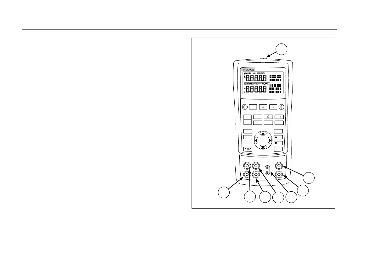
Getting Acquainted with the Calibrator
Input and Output Terminals
Figure 2 shows the calibrator input and output terminals.
Table 3 explains their use.
1
725
MULTIFUNCTION CALIBRATOR
V mA
TC RTD
ZERO
Hz
C ˚F
˚
100%
25%
25%
0%
MEAS
SOURCE
STORE
SETUP
RECALL
V mA
LOOP
2
8
7
6
5
3
4
sh05f.eps
Figure 2. Input/Output Terminals and Connectors
8

Table 3. Input/Output Terminals and Connectors
No Name Description
Getting Acquainted with the Calibrator
A
B, C
D
E, F
G, H
Pressure module
connector
MEASURE V, mA
terminals
TC input/output Terminal for measuring or simulating thermocouples. This terminal accepts a miniature
SOURCE/ MEASURE
V, RTD, Hz, Ω
terminals
SOURCE/ MEASURE
mA terminals, 3W, 4W
Connects the calibrator to a pressure module or the calibrator to a PC for a remote
control connection.
Input terminals for measuring voltage, current, and supplying loop power.
polarized thermocouple plug with flat, in-line blades spaced 7.9 mm (0.312 in) center to
center.
Terminals for sourcing or measuring voltage, resistance, frequency, and RTDs.
Terminals for sourcing and measuring current, and performing 3W and 4W RTD
measurements.
9
725
Users Manual
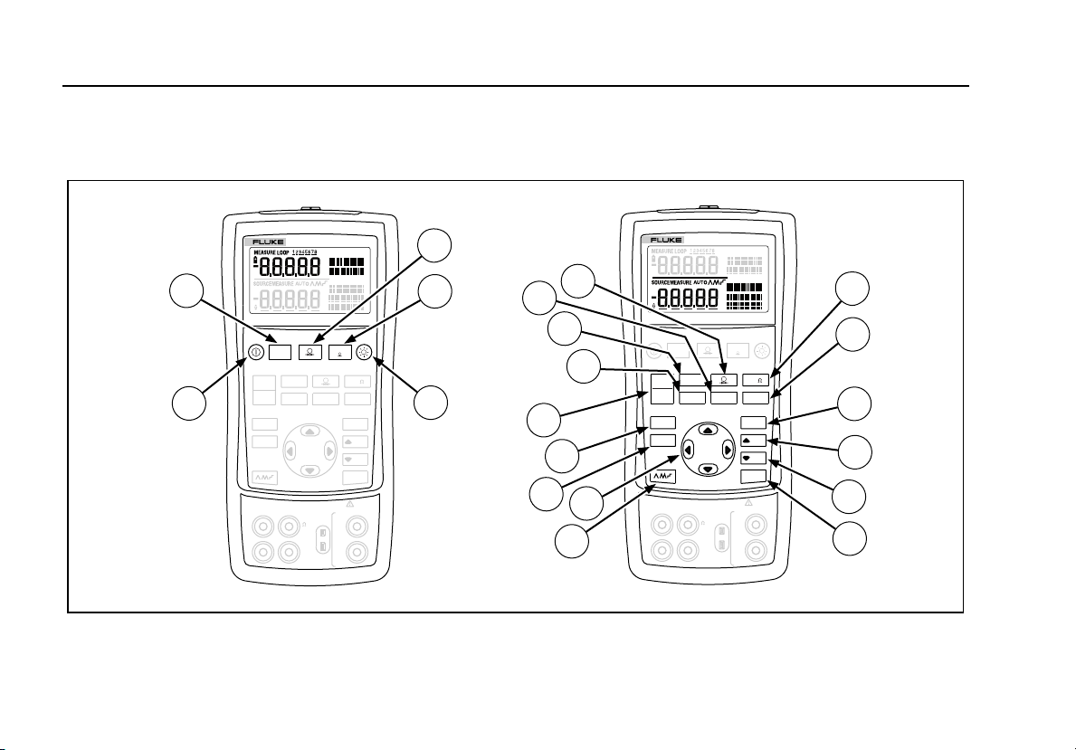
Keys
Figure 3 shows the calibrator keys and Table 4 explains
their use.
725
MULTIFUNCTION CALIBRATOR
3
725
MULTIFUNCTION CALIBRATOR
10
2
4
20
19
18
V mA
TC RTD
30V MAX ALL TERMINALS
V
TC
Hz
RTD
COM COM
ZERO
Hz
C ˚F
˚
100%
25%
25%
0%
MEASURE
V
mA
LOOP
V mA
TC RTD
V
Hz
RTD
COM COM
ZERO
16
14
17
15
13
12
Hz
C ˚F
˚
100%
25%
25%
0%
MEASURE
V
TC
mA
LOOP
5
V mA
LOOP
MEAS
1
SOURCE
STORE
SETUP
RECALL
SOURCE / MEASURE
+
mA
3W
-
mA
4W
30V MAX ALL TERMINALS
MEAS
SOURCE
STORE
SETUP
RECALL
SOURCE / MEASURE
+
mA
3W
-
mA
4W
V mA
LOOP
6
7
8
9
10
11
sh41f.eps
Figure 3. Keys

Getting Acquainted with the Calibrator
Table 4. Key Functions
No Name Description
A O Turns the power on or off.
B l Selects voltage, mA or Loop Power measurement function in the upper display.
C A Selects the pressure measurement function in the upper display. Repeated pushes cycle
through the different pressure units.
D K Zeros the pressure module reading. This applies to both upper and lower displays.
E C Turns backlight on or off. Turns Contrast Adjust mode on when powering up.
F F Toggles frequency and ohms measurement and sourcing functions.
G D Toggles between Centigrade or Fahrenheit when in TC or RTD functions.
H G Recalls from memory a source value corresponding to 100 % of span and sets it as the
source value. Press and hold to store the source value as the 100 % value.
I H Increments output by 25 % of span.
J I Decrements output by 25 % of span.
K J Recalls from memory a source value corresponding to 0 % of span and sets it as the
source value. Press and hold to store the source value as the 0 % value.
Identifies Firmware version. Press and hold J when powering up.
11

725
Users Manual
Table 4. Key Functions (cont.)
No Name Description
L L
AM
AMOYOZ
M XW
Y Z
N Q
O S
P
M
Q T
R V
S R
T U
12
Cycles through :
E
Slow repeating 0 % - 100 % - 0 % ramp
P
Fast repeating 0 % - 100 % - 0 % ramp
N
Repeating 0 % - 100 % - 0 % ramp in 25 % steps
Disables Shut Down Mode
Enables Shut Down Mode
Increases or decreases the source level.
Cycles through the 2-, 3-, and 4-wire selections.
Moves through the memory locations of calibrator setups.
In Contrast Adjustment mode; up-darkens contrast, down-lightens contrast.
Retrieves a previous calibrator setup from a memory location.
Saves the calibrator setup. Saves Contrast Adjust setup.
Cycles the calibrator through MEASURE and SOURCE modes in the lower display.
Selects TC (thermocouple) measurement and sourcing function in the lower display. Repeated pushes cycle through
the thermocouple types.
Toggles between voltage, mA sourcing, or mA simulate functions in the lower display.
Selects RTD (resistance temperature detector) measurement and sourcing function in lower display. Repeated pushes
cycle through the RTD types.
Selects the pressure measurement and sourcing function. Repeated pushes cycle through the different pressure units.
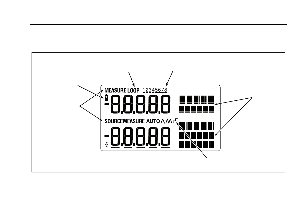
Display
Figure 4 shows the elements of a typical display.
Getting Acquainted with the Calibrator
Low Battery
Symbol
Mode
Indicator
Loop
Annunciator
Memory Locations
for Calibrator Setups
Figure 4. Elements of a Typical Display
Units
Display
Auto
Ramp
sh07f.eps
13
Loading...