


 Loading...
®
1625
Earth/Ground Tester
Users Manual
January 2006
© 2006 Fluke Corporation, All rights reserved. Printed in USA All product names are trademarks of their respective companies.
LIMITED WARRANTY AND LIMITATION OF LIABILITY
Each Fluke product is warranted to be free from defects in material and workmanship under normal use and service. The warranty period is two years and begins on the date of shipment. Parts, product repairs, and services are warranted for 90 days. This warranty extends only to the original buyer or end-user customer of a Fluke authorized reseller, and does not apply to fuses, disposable batteries, or to any product which, in Fluke's opinion, has been misused, altered, neglected, contaminated, or damaged by accident or abnormal conditions of operation or handling. Fluke warrants that software will operate substantially in accordance with its functional specifications for 90 days and that it has been properly recorded on non-defective media. Fluke does not warrant that software will be error free or operate without interruption.
Fluke authorized resellers shall extend this warranty on new and unused products to enduser customers only but have no authority to extend a greater or different warranty on behalf of Fluke. Warranty support is available only if product is purchased through a Fluke authorized sales outlet or Buyer has paid the applicable international price. Fluke reserves the right to invoice Buyer for importation costs of repair/replacement parts when product purchased in one country is submitted for repair in another country.
Fluke's warranty obligation is limited, at Fluke's option, to refund of the purchase price, free of charge repair, or replacement of a defective product which is returned to a Fluke authorized service center within the warranty period.
To obtain warranty service, contact your nearest Fluke authorized service center to obtain return authorization information, then send the product to that service center, with a description of the difficulty, postage and insurance prepaid (FOB Destination). Fluke assumes no risk for damage in transit. Following warranty repair, the product will be returned to Buyer, transportation prepaid (FOB Destination). If Fluke determines that failure was caused by neglect, misuse, contamination, alteration, accident, or abnormal condition of operation or handling, including overvoltage failures caused by use outside the product’s specified rating, or normal wear and tear of mechanical components, Fluke will provide an estimate of repair costs and obtain authorization before commencing the work. Following repair, the product will be returned to the Buyer transportation prepaid and the Buyer will be billed for the repair and return transportation charges (FOB Shipping Point).
THIS WARRANTY IS BUYER'S SOLE AND EXCLUSIVE REMEDY AND IS IN LIEU OF ALL OTHER WARRANTIES, EXPRESS OR IMPLIED, INCLUDING BUT NOT LIMITED TO ANY IMPLIED WARRANTY OF MERCHANTABILITY OR FITNESS FOR A PARTICULAR PURPOSE. FLUKE SHALL NOT BE LIABLE FOR ANY SPECIAL, INDIRECT, INCIDENTAL OR CONSEQUENTIAL DAMAGES OR LOSSES, INCLUDING LOSS OF DATA, ARISING FROM ANY CAUSE OR THEORY.
Since some countries or states do not allow limitation of the term of an implied warranty, or exclusion or limitation of incidental or consequential damages, the limitations and exclusions of this warranty may not apply to every buyer. If any provision of this Warranty is held invalid or unenforceable by a court or other decision-maker of competent jurisdiction, such holding will not affect the validity or enforceability of any other provision.
Fluke Corporation |
Fluke Europe B.V. |
P.O. Box 9090 |
P.O. Box 1186 |
Everett, WA 98206-9090 |
5602 BD Eindhoven |
U.S.A. |
The Netherlands |
11/99
Table of Contents
Title |
Page |
Introduction .......................................................................................... |
1 |
Models and Accessories........................................................................ |
3 |
Safety Instructions ................................................................................ |
4 |
Qualified Staff .................................................................................. |
5 |
Setup ..................................................................................................... |
5 |
Unpacking......................................................................................... |
5 |
Checking the Scope of Delivery ....................................................... |
5 |
General ................................................................................................. |
6 |
Additional Accessories ......................................................................... |
6 |
Assembly .............................................................................................. |
7 |
Description of Functions....................................................................... |
7 |
Measurement of Interference Voltage (UST) ..................................... |
8 |
Measurement of Interference Frequency (FST).................................. |
8 |
Measurement of Earthing Resistance (RE)........................................ |
9 |
Selective Measurement of Earthing Resistance (RE A) ................ |
9 |
Resistance Measurement (R~) .......................................................... |
9 |
Low Resistance Measurement (RF)................................................. |
9 |
Checking for Correct Measuring Connection ................................... |
9 |
Beeper............................................................................................... |
9 |
LO-BAT............................................................................................ |
10 |
Specifications........................................................................................ |
10 |
Measurement of Interference Voltage DC + AC (UST) ..................... |
13 |
Measurement of Interference Frequency (FST).................................. |
13 |
Earthing Resistance (RE)................................................................... |
13 |
Selective Measurement of the Earthing Resistance (REA)............ |
17 |
Resistance Measurement (R~) .......................................................... |
18 |
Resistance Measurement (RF)......................................................... |
19 |
Compensation of Lead Resistance (RK) ............................................ |
20 |
Description of the Operating Elements ................................................. |
21 |
Description of Display Elements ...................................................... |
23 |
Procedure of Measurements.................................................................. |
24 |
POWER ON Functions ................................................................. |
25 |
Operation ...................................................................................... |
26 |
Checking of Correct Measuring Connection (Socket Allocation). 30 |
|
Safety Control Measurements....................................................... |
31 |
i

1625
Users Manual
Measurement of Interference - Voltages and Frequencies................ |
31 |
Measurement of Earthing Resistances.............................................. |
32 |
3-pole/4-pole Measurement of Earthing Resistance ..................... |
33 |
Measurement of Single Earth Electrode Resistances in |
|
Mesh Operated Earthing Systems Using Selective Clamp |
|
Method ......................................................................................... |
36 |
3-pole/4-pole Measurement of Single Earth Electrode |
|
Resistances ................................................................................... |
37 |
Measurements on High Voltage Pylons........................................ |
39 |
Correcting Clip-on Transformer Errors ........................................ |
42 |
Compensation of Earth Electrode Connecting Lead..................... |
44 |
Measurement of Soil Resistivity....................................................... |
45 |
Measurement of Resistances ............................................................ |
48 |
Resistance Measurement (R~)...................................................... |
48 |
Resistance Measurement (RF)..................................................... |
49 |
Compensation of Measuring Lead Resistance.............................. |
50 |
Changing of All Data Settings with Personalized CODE................. |
51 |
Storing a Code.............................................................................. |
53 |
Deleting a Code............................................................................ |
54 |
Description of Displays ........................................................................ |
55 |
Care and Maintenance .......................................................................... |
60 |
Replacing Batteries........................................................................... |
61 |
Recalibration .................................................................................... |
62 |
Storage.............................................................................................. |
62 |
Specifications ....................................................................................... |
64 |
Principle of Operation .......................................................................... |
65 |
Purpose............................................................................................. |
65 |
Operation.......................................................................................... |
68 |
Settings on the Tester ................................................................... |
69 |
Applications ..................................................................................... |
70 |
Description of Displays ................................................................ |
72 |
ii
List of Tables
|
Table |
Title |
Page |
1. |
Models and Accessories |
................................................. |
3 |
2. |
Electrical Measurement Specifications .......................... |
14 |
|
3. |
Description of Displays.................................................. |
|
56 |
iii

1625
Users Manual
iv
List of Figures
|
Figure |
Title |
Page |
1. |
Fluke 1625 Earth/Ground Tester.................................... |
2 |
|
2. |
Description of Functions |
................................................ |
8 |
3. |
Display ........................................................................... |
|
10 |
4. |
Operating Elements........................................................ |
|
21 |
5. |
Display Elements ........................................................... |
|
23 |
6. |
Operational Modes ......................................................... |
|
27 |
7.Measurement of Interference -
|
Voltages and Frequencies............................................... |
32 |
8. |
Earthing Resistances Measurement - Method................ |
33 |
9.3-pole/4-pole Measurement of Earthing Resistance -
Process............................................................................ |
34 |
10. Earth Resistance - Maximum Permissible Value ........... |
35 |
11.Measurement of Single Earth Electrode Resistances in
Mesh Operated Earthing Systems .................................. |
36 |
12.3-pole/4-pole Measurement of Single Earth
Electrode Resistances..................................................... |
37 |
13.Measuring the Earthing Resistance without
|
Disengaging the Overhead Earth Wire........................... |
40 |
14. |
Correcting Clip-on Transformer Errors.......................... |
43 |
15. |
Compensation of Earth Electrode Connecting Lead ...... |
44 |
16. |
Measurement of Soil Resistivity .................................... |
45 |
17. |
Resistance Measurement (R~) ....................................... |
48 |
18. |
Resistance Measurement (RF) ...................................... |
49 |
19. |
Evaluation of Measured Value....................................... |
50 |
20. |
Compensation of Measuring Lead Resistance ............... |
51 |
v

1625
Users Manual
vi
Earth/Ground Tester
Introduction
At locations involving the generation, distribution and consumption of electrical energy, certain safety measures must be met in order to protect human life. In many cases, these safety measures are national and international regulations which must be checked regularly. Grounding, the connection of exposed conductive parts to the earth in case of a fault, represents the most fundamental safety measure. There are requirements for grounding of transformers, high and medium voltage power pylons, railway tracks, tanks, vats, foundations and lightning protection systems.
The effectiveness of grounding systems should be checked using a ground test instruments such as the 1625 which checks the effectiveness of connections to the ground. The 1625 provides the perfect solution by combining the latest technology into a compact, field-rugged and extremely easy to use instrument. In addition to performing standard 3- and 4-pole ground resistance measurements, an innovative process accurately measures individual earth electrode resistances in single and meshed earthed systems without disconnecting any parallel electrodes. One specific application of this capability is quick and accurate measurement of power pylon grounds. The 1625 also incorporates automatic frequency control (AFC) to minimize interference. Before measuring, the instrument identifies existing interference and selects a measurement frequency to minimise its effect. The 1625 incorporates microprocessor controlled automatic measurements including checking probe hookup to ensure that measurements are taken correctly. It measures all probe ground resistances to ensure reliable, repeatable results. Probe resistance and auxiliary earth resistance are also measured and displayed.
1
1625
Users Manual
Notes
•The terms earth and earthing also refer to ground and grounding and is used interchangeably throughout this manual.
•For stakeless earth resistance measurements, the EI-1625 must be purchased. (The EI-1625 comes standard with the 1625 Kit). Refer to Appendix A for a complete set of operating information including specifications.
•Selective measurements are described in the main section of this manual.
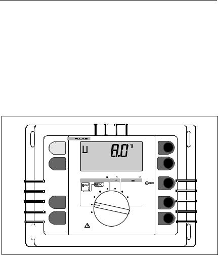
Figure 1 displays the Fluke 1625 Earth/Ground Tester:
|
1625 EARTH / GROUND TESTER |
||
START |
ST |
|
H/C2 |
TEST |
|
|
|
DISPLAY |
|
|
S/P2 |
MENU |
|
|
|
|
|
|
|
|
|
AC |
|
|
Earth/Ground Resistance 300 k |
Resistance |
DC Low Resistance 3k |
|
300 k |
||
|
RA |
R |
R |
|
4 POLE |
2 POLE |
|
|
|
2 POLE |
|
|
3 POLE |
|
|
|
4 POLE |
|
4 POLE |
CHANGE |
3 POLE |
|
ES/P1 |
ITEM |
|
||
|
|
||
|
OFF |
|
|
SELECT |
|
|
E/C1 |
|
|
|
edw001.eps |
Figure 1. Fluke 1625 Earth/Ground Tester
2
Earth/Ground Tester
Models and Accessories
Models and Accessories
Table 1 lists the models and accessories.
Table 1. Models and Accessories
Description |
Item/Part Number |
|
|
Earth Ground Tester - Basic |
Fluke-1625 |
(Includes manual, 2 leads and 2 clips) |
|
|
|
Earth Ground Tester - Fully Loaded |
Fluke-1625 Kit |
(Includes manual, 2 leads and 2 clips, |
|
ES162P4, EI-1623) |
|
|
|
Service Replacement Kit |
Fluke-162x-7001 |
(Includes 2 Leads, 2 Clips) |
|
|
|
Stake Set for 3 Pole Measurement |
ES-162P3 |
(Includes three stakes, one 25 m cable |
|
reel, one 50 m cable reel) |
|
|
|
Stake set for 4 Pole Measurement |
ES-162P4 |
(Includes four stakes, two 25 m cable |
|
reels, one 50 m cable reel) |
|
|
|
Selective/Stakeless Clamp Set for |
EI-1625 |
1625. (Includes EI-162X and EI- |
|
162AC and 2-3 wire adapter cable) |
|
|
|
Clip-on Current Transformer (sensing) |
EI-162X |
with shielded cable set |
|
|
|
Shielded Cable (Used w/EI-162X |
2539195 |
Clamp) |
|
|
|
Clip-on Current Transformer (inducing) |
EI-162AC |
|
|
12.7 Inch (320mm) Spilt Core Trans- |
EI-162BN |
former |
|
|
|
2-3 Wire Adapter Cable for 1625 for EI- |
2577171 |
162AC Current Transformer |
|
|
|
Earth Stake |
2539121 |
|
|
Cable Reel w/25m Wire |
2539100 |
|
|
Cable Reel w/50m Wire |
2539117 |
|
|
1625 Users Manual |
2560348 |
|
|
3

1625
Users Manual
Safety Instructions
W Warning
This measuring equipment is only to be operated by qualified staff and in accord with its technical data in compliance with the safety precautions and instructions set forth below. In addition, use of this equipment requires compliance with the legal and safety instructions pertaining to the specific application in question. Similar precuations apply to the use of accessories.
Caution
Operation of electrical equipment inevitably causes certain parts of such equipment to carry dangerous voltage. Noncompliance with precautions may therefore cause major physical or material damage.
Fault-free and reliable operation of this instrument requires suitable transport and storage, setting-up and assembly, as well as care in operation and maintenance.
If there is reason to believe that risk-free operation is no longer possible, the instrument should be switched off immediately and protected against accidental restarting. Risk-free operation shall be deemed to be no longer possible if and when the instrument
•shows visible damage,
•fails to work in spite of functioning batteries,
•has been exposed for some time to unfavorable conditions ( e.g. storage beyond the permissible climatic limits without adaptation to the ambient climate, dewing etc.),
•has been exposed to major strain during transport ( e.g. been dropped from some height without visible external damage etc.), or
•shows " E1 ... E5 " on the display.
4

Earth/Ground Tester
Setup
Qualified Staff
Consists of persons familiar with the setting up, assembly, starting up and operation of the product and possess the qualifications required for such activities, such as
•training, instruction and/or authorization to perform the following operations on circuits and equipment according to safety engineering standards: switching on and off, disconnecting, earthing/grounding, labeling;
•training or instructions according to safety engineering standards in the care and main tenance of adequate safety equipment.
•training in rendering first aid.
Setup
Unpacking
Check delivery for damage during transport. Keep the packing material for later transport and check scope of delivery.
Checking the Scope of Delivery
Upon unpacking immediately check the accessories for missing parts. The accessories supplied are listed on page 2.
Caution
Although the instrument is easy to operate please read these operating instructions carefully for safety reasons and in order to make optimum use of the instrument.
The measuring functions are only all activated when the instrument is connected.
5

1625
Users Manual
General
Microprocessor controlled universal earth resistance meter with fully automated measuring frequency selection process as well as automatic testing of probeand auxiliary earth electrode resistances and possible interference voltages as per DIN IEC61557-5/EN61557-5.
•Measurement of interference voltage (UST)
•Measurement of interference frequency (FST)
•Measurement of probe resistance (RS)
•Measurement of auxiliary earth electrode resistance (RH)
•Measurement of earthing resistance 3pole, 4pole, (RE) with or without using the external clip-on current transformer for selective measurement of single earthing branches in mesh operated earthing systems
A
•Resistance measurement 2pole with AC voltage (R~)
•Resistance measurement with DC voltage 2pole, 4pole, (RF)
With its various possibilities of measurement and the fully automated measuring sequence control (incl. automatic frequency control AFC), this instrument offers the latest measuring technology in the field of earthing resistance measurements. By means of the selectable limit input with visual and accoustical confirmation/error message and with the code programmable and customer defined special functions, e.g. measuring voltage 20 V (for agricultural systems), earthing impedance R* (measuring frequency 55 Hz) switched on or off etc., these instruments are individually programmable for use as a simple meter as well as a high end fully automated measuring device.
Additional Accessories
An external current transformer with a transformation ratio between 80 and 1200:1 for the measurement of a single branch in mesh operated earthing systems is available as an option and enables the user to measure on high voltage pylons without seperating the overhead earth wires or earth strips at the bottom of the pylons and also to measure lightning protection systems without seperating the individual lightning protection wires.
6

Earth/Ground Tester
Assembly
Assembly
The instrument is made up of two parts:
1.The base part which contains the measuring electronics.
2.The protective housing.
The functions are selected with the central rotary switch. Four rubber buttons, which start measurements, read out supplementary measuring values and select special functions, are located on the left hand side of the front panel. This design enables quick and clear one-hand operation.
The measured values are displayed on a liquid crystal display with correct decimal point and unit. Various additional special characters indicate measuring mode, operating condition and error messages.
The auxiliary power supply consists of 6 x 1.5 V batteries (IEC R6 or LR6 or type AA).
This device has been developed, designed and manufactured in compliance with quality system DIN ISO 9001.
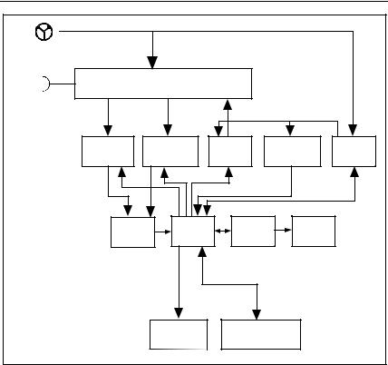
Description of Functions
The following flowchart presents a description of the functions of the 1625 Earth/Ground Tester.
7
1625
Users Manual
EXT |
|
|
|
|
|
|
H |
|
|
|
|
|
|
S |
Switching |
|
|
|
|
|
ES |
|
|
|
|
|
|
E |
|
|
|
|
|
|
Voltage |
|
Current |
Source |
|
Undervoltage |
Supply |
measurement |
|
measurement |
|
detection |
voltage |
|
|
|
|
||||
ADC |
|
Processor |
|
LCD |
Display |
|
Comp |
|
driver |
|
|||
|
|
|
|
|||
|
|
Relais |
Rotary selector |
|
||
|
|
driver |
switch buttons |
|
||
|
|
|
|
|
|
edw003.eps |
Figure 2. Description of Functions
Measurement of Interference Voltage (UST)
Fullwave rectification for DC and AC (DC without operational sign, AC signal sinus calibrated for r.m.s. values). If limit values are exceeded no measurement will be started.
Measurement of Interference Frequency (FST)
For interference voltage >1 V its frequency is derived from the period time.
8

Earth/Ground Tester
Description of Functions
Measurement of Earthing Resistance (RE)
The earthing resistance is determined by a 3- or 4-pole current and voltage measurement. The measuring voltage is a square pulse AC voltage with 48 / 20 V and a frequency of 94, 105, 111 or 128 Hz. The frequency can be selected manually or automatically (AFC).
Selective Measurement of Earthing Resistance (RE A)
Measurement of a single earth electrode in a mesh operated (parallel) earthing system. The current flowing through the single earth electrode is measured with an external current transformer.
Resistance Measurement (R~)
The resistance is determined by a 2 pole current and voltage measurement. The measuring voltage is a square pulse AC voltage with 20 V and a frequency of 94, 105, 111 or 128 Hz. The frequency can be selected manually or automatically (AFC).
Low Resistance Measurement (RF)
The resistance is determined by DC current and voltage measurement. 2- as well as 4-pole measurement is possible. The short circuit current is > 200 mA. The resistance of both current directions is measured and stored.
Checking for Correct Measuring Connection
The processor checks if the measuring lead is properly connected according to the selected function via isolated, two piece contacts, inside of each 4 mm (banana) input socket, in combination with detection circuitry. A wrong or missing connection is indicated by an optical or acoustical signal.
Beeper
The built in beeper has two functions:
1.Giving messages if set limit values are exceeded.
2.Indicating dangerous conditions or maloperation. Controlling is done by means of the microprocessor.
9
1625
Users Manual
LO-BAT
Supervision of the battery charge status is done with a comparator circuit. Via microprocessor, a drop in battery capacity down to typ. 10 % of its specified value is indicated on the display with symbol LO-BAT.
Specifications
General: |
Microprocessor controlled, fully automated earth |
|
measuring instrument with additional functions |
Measuring function: |
interference voltage and frequency, earthing resis- |
|
tance 3- and 4-pole with / without clip-on current |
|
transformer, resistance 2-pole with AC, 2- and 4-pole |
|
with DC |
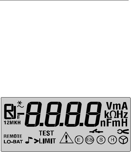
Display |
4 digit (2999 Digit) - 7 segment liquid crystal display, |
(see Figure 4): |
digit size 18 mm with supplementary signs and active |
|
illumination. |
ST
edw004.eps
Figure 3. Display
10
|
|
|
Earth/Ground Tester |
|
|
|
Specifications |
|
|
||
Operation: |
Central rotary switch and function keys |
||
Working temperature range: |
-10 °C |
… +50 °C |
|
Operating temperature range: |
0 |
°C |
… +35 °C |
Nominal temperature range: |
18 |
°C |
… +28 °C |
Storage temperature range: |
-30 °C |
… +60 °C |
|
Note
The chart of four temperature ranges for the instrument exist to satisfy European Standards requirements; the instrument can be used over the full Working temperature range by using the temperature coefficient to calculate accuracy at the ambient temperature of use.
Temperature coefficient: |
± 0.1 % of range / Kelvin |
Operating errors: |
refer to operating temperature range and RH |
|
< 20 RE, RS < 100 RE |
The maximum percentage operating error within the measurement range does not exceed ± 30 % with the measured value as fiducial value, as determined in accordance with TABLE 1.
The operating error applies under the rated operating conditions given in IEC1557-1 and the following:
•injection of series interference voltages with system frequencies of 400 Hz, 60 Hz, 50 Hz, 16 2/3 Hz or with d.c. voltage respectively across the terminals E (ES) and S. The r.m.s. value of the series interference voltage shall be 3 V;
•resistance of the auxiliary earth electrode and of the probes: 0 to 100 x RA but ≤ 50 kΩ;
•system voltages between 85 % and 110 % of the nominal voltage and between 99 % and 101 % of the nominal system frequency for measuring equipment with a mains supply and/or measuring equipment deriving its output voltage directly from the distribution system.
Limits of error: |
refer to nominal temperature range |
Climate class: |
C1 (IEC 654-1), -5 °C...+45 °C, 5 %...95 % RH |
Type of protection: |
IP 56 for case, IP 40 for battery door according to |
|
EN 60529 |
11
1625 |
|
|
Users Manual |
|
|
|
|
|
Max voltage: |
Wsocket Ato socket EFGH |
|
|
||
|
Urms = 0 V |
|
|
Sockets ” E ES S H " to each other in any com- |
|
|
bination, max. Urms= 250 V (pertains to misuse) |
|
EMC (Emission Im- |
IEC 61326-1:1997 Class A |
|
munity): |
|
|
Quality standard: |
developed, designed and manufactured to comply |
|
|
with DIN ISO 9001 |
|
External field influ- |
complies with DIN 43780 (8/76) |
|
ence: |
|
|
Auxiliary power: |
6 x |
1,5 V alkali-manganese-batteries (IEC |
|
|
LR6 or type AA ) |
Battery life span: |
with IEC LR6/type AA: typ. 3000 measurements |
|
|
(RE+RH ≤ 1 kΩ) |
|
|
with IEC LR6/type AA : typ. 6000 measurements |
|
|
(RE + RH >10 kΩ) |
|
Dimensions: |
240 mm (W) x 220 mm (D) x 90 mm ( H ) |
|
Weight: |
≤ 1.1 kg without accessories |
|
|
≤ 5.5 kg incl. accessories and batteries in carrying |
|
|
case |
|
Case material: |
NORYL, shock -and scratch proof thermoplast |
|
12
Earth/Ground Tester
Specifications
Measurement of Interference Voltage DC + AC (UST)
Measuring method: |
fullwave rectification |
|
|
|
|
|
||||||
|
|
|
|
|
|
|
|
|
|
|
|
|
Measuring |
|
Display |
|
Resolu- |
Frequency |
|
Limits of Er- |
|
||||
Range |
|
Range |
|
tion |
|
Range |
|
|
ror |
|
||
|
|
|
|
|
|
|
|
|
|
|
|
|
1…50 V |
|
0.0…50 V |
|
0.1 V |
|
DC/AC |
|
|
± (5% of |
|
||
|
|
|
|
|
|
|
45…400 Hz |
|
reading +5 |
|
||
|
|
|
|
|
|
|
sine |
|
|
digit) |
|
|
|
|
|
|
|
|
|
|
|
|
|
|
|
Measuring sequence: |
approx. 4 measurements /s |
|
|
|
||||||||
Internal resistance: |
approx. 1.5 MΩ |
|
|
|
|
|
||||||
Max. overload: |
|
Urms = 250 V |
|
|
|
|
|
|||||
Measurement of Interference Frequency (FST) |
|
|||||||||||
Measuring method: |
Measurement of oscillation period of the interfer- |
|
||||||||||
|
|
|
ence voltage |
|
|
|
|
|
|
|||
|
|
|
|
|
|
|
|
|
|
|
|
|
Measuring |
Display Range |
|
Resolution |
Range |
|
Limits of |
|
|||||
Range |
|
|
Error |
|
||||||||
|
|
|
|
|
|
|
|
|
|
|||
|
|
|
|
|
|
|
|
|||||
16.0 … 400 |
16.0…299.9…99 |
|
0.1 … 1 Hz |
1 V … |
|
± (1% v. mv |
|
|||||
Hz |
9 Hz |
|
|
|
|
|
50 V |
|
+2 digit) |
|
||
|
|
|
|
|
|
|
|
|
|
|||
Earthing Resistance (RE) |
|
|
|
|
|
|
|
|||||
Measuring method: |
|
current and voltage measurement with probe |
|
|||||||||
|
|
|
|
as IEC61557-5 |
|
|
|
|
|
|||
Open circuit voltage: |
|
20 / 48 V, AC |
|
|
|
|
|
|||||
Short circuit current: |
|
250 mA |
AC |
|
|
|
|
|
||||
Measuring frequency: |
|
94 , 105 , 111 , 128 Hz selected manually or |
|
|||||||||
|
|
|
|
automatic.(AFC) 55 Hz in function R* |
|
|||||||
Noise rejection: |
|
|
120 dB ( 16 2/3, 50 , 60, 400 Hz ) |
|
||||||||
Max. overload: |
|
|
Urms = 250 V |
|
|
|
|
|
||||
13

1625
Users Manual
Table 2. Electrical Measurement Specifications
|
|
|
Requirements |
|
|
Intrinsic Er- |
Reference Con- |
|
or Test in Ac- |
Type |
|
ror or Influ- |
ditions or Speci- |
Designation |
cordance with |
||
of |
|||||
ence Quan- |
fied Operating |
Code |
the Relevant |
||
Test |
|||||
tity |
Range |
|
Parts of |
||
|
|
||||
|
|
|
IEC 1557 |
|
|
|
|
|
|
|
|
Intrinsic error |
Reference condi- |
A |
Part 5, 6.1 |
R |
|
|
tions |
|
|
|
|
|
|
|
|
|
|
Position |
Reference posi- |
E1 |
Part 1, 4.2 |
R |
|
|
tion |
|
|
|
|
|
± 90° |
|
|
|
|
|
|
|
|
|
|
Supply volt- |
At the limits |
E2 |
Part 1, 4.2, |
R |
|
age |
stated by the |
|
4.3 |
|
|
|
manufacturer |
|
|
|
|
|
|
|
|
|
|
Temperature |
0 °C and 35 °C |
E3 |
Part 1, 4.2 |
T |
|
|
|
|
|
|
|
Series inter- |
See 4.2 and 4.3 |
E4 |
Part 5, 4.2, |
T |
|
ference volt- |
|
|
4.3 |
|
|
age |
|
|
|
|
|
|
|
|
|
|
|
Resistance |
0 to 100 x RA |
E5 |
Part 5, 4.3 |
T |
|
of the probes |
but ≤ 50 kΩ |
|
|
|
|
and auxiliary |
|
|
|
||
|
|
|
|
||
earth elec- |
|
|
|
|
|
trodes |
|
|
|
|
|
|
|
|
|
|
|
System fre- |
99 % to 101 % of |
E7 |
Part 5, 4.3 |
T |
|
quency |
the nominal fre- |
|
|
|
|
|
quency |
|
|
|
|
|
|
|
|
|
|
System volt- |
85 % to 110 % of |
E8 |
Part 5, 4.3 |
T |
|
age |
the nominal volt- |
|
|
|
|
|
age |
|
|
|
|
|
|
|
|
|
|
Operating |
|
|
Part 5, 4.3 |
R |
|
error |
B = ±( A +1,15 E12 E22 E32 E42 E52 E62 E72 E82 |
|
|
||
|
|
|
|
|
|
14

|
|
|
|
|
|
|
|
|
Earth/Ground Tester |
||
|
|
|
|
|
|
|
|
|
Specifications |
||
|
|
|
|
|
|
|
|
|
|
|
|
|
|
|
|
|
|
|
|
|
|
|
|
|
|
A |
= |
intrinsic error |
B[%]= ± |
|
B |
|
x 100% |
||
|
|
En |
|
= |
variations |
fiducial value |
|||||
|
|
R |
= |
routine test |
|
|
|
|
|
||
|
|
T |
= |
type test |
|
|
|
|
|
||
|
|
|
|
|
|
|
|
|
|
|
|
|
|
|
|
|
|
|
|
|
|
|
|
|
|
Measuring |
|
|
|
|
Instrinsic |
Max. Op- |
|||
|
|
Display Range |
|
Resolution |
|
|
erating |
||||
|
|
Range |
|
|
Error |
|
|||||
|
|
|
|
|
|
|
Error |
||||
|
|
|
|
|
|
|
|
|
|
|
|
|
|
|
|
|
|
|
|
|
|
|
|
|
|
|
|
|
0.001 Ω...2.999 Ω |
|
0.001 Ω |
|
|
|
|
|
|
|
|
|
|
|
|
|
|
|
|
|
|
|
|
|
3.00 Ω...29.99 Ω |
|
0.01 Ω |
|
|
|
|
|
|
|
|
|
|
|
|
|
|
||
|
|
0.020 Ω |
30.0 Ω...299.9 Ω |
|
0.1 Ω |
|
± ( 2 % of |
|
± ( 5% of |
||
|
|
|
|
|
|
|
|
|
mv +2 digit ) |
|
mv +5 |
|
|
300 kΩ |
|
0.300 kΩ...2.999 kΩ |
|
1 Ω |
|
|
|||
|
|
|
|
|
|
|
digit ) |
||||
|
|
|
|
|
|
|
|
|
|
|
|
|
|
|
|
|
|
|
|
|
|
|
|
|
|
|
|
|
3.00 kΩ...29.99 kΩ |
|
10 Ω |
|
|
|
|
|
|
|
|
|
|
|
|
|
|
|
|
|
|
|
|
|
30.0 kΩ...299.9 kΩ |
|
100 Ω |
|
|
|
|
|
|
|
|
|
|
|
|
|
|
|
|
Measuring time:
Additional error because of probe-and auxiliary earth electrode resistance:
Measuring error of RH and RS:
Max. probe resistance:
Max. auxiliary earth electrode resistance:
typ. 8 sec. with a fixed frequency
30 sec. max. with AFC and complete cycle of all
measuring frequencies
RH (RS + 2000Ω) × 1.25× 10− 6% + 5digits RE
typ. 10 % of RE + Rs + RH
≤1 M Ω
≤1 M Ω
Automatic check if error is kept within the limits required by IEC61557-5.
If after a measurement of probe-, auxiliary earth electrodeand earthing resistance, a measurement error of higher than 30 % is assumed because of the in-
15

1625
Users Manual
fluencing conditions (see diagramm), the display shows a warning symbol W and a notice that RS or RH are too high.
F |
|
|
|
3000 |
1000 |
|
1000% |
|
|
|
|
||
|
|
|
|
|
|
|
|
|
|
|
|
RH/RE= 300 |
|
100% |
|
|
|
|
100 |
|
|
|
|
|
|
|
|
|
|
|
|
|
30 |
|
10% |
|
|
|
|
10 |
|
|
|
|
|
|
|
|
|
|
|
|
|
3 |
|
1% |
|
|
|
|
1 |
|
|
|
|
|
|
|
|
|
|
|
|
|
0,3 |
|
0,1% |
|
|
|
|
|
|
10 |
100 |
1k |
10k |
100k |
1M |
RS |
|
|
|
|
|
|
edw005.eps |
Automatic switchover of measuring resolution in dependence to auxiliary earth electrode resistance RH:
RH with Umeas = 48 V |
RH with Umeas = 20 V |
Resolution |
|
|
|
|
|
< 300 Ω |
< 250 Ω |
1 mΩ |
|
|
|
|
|
< |
6 kΩ |
< 2,5 kΩ |
10 mΩ |
|
|
|
|
< |
60 kΩ |
< 25 kΩ |
100 mΩ |
|
|
|
|
< 600 kΩ |
< 250 kΩ |
1 Ω |
|
|
|
|
|
16

Earth/Ground Tester
Specifications
Selective Measurement of the Earthing Resistance
(REA)
Measuring method: |
Current and voltage measurement with probe as per |
|||||
|
|
|
EN61557-5 and current measurement in the individual |
|||
|
|
|
branch with additional current transformer (patent ap- |
|||
|
|
|
plied for). |
|
|
|
Open circuit volt- |
20 / 48 V AC |
|
|
|||
age: |
|
|
|
|
|
|
Short circuit current: |
250 mA AC |
|
|
|||
Measuring fre- |
|
94, 105, 111, 128 Hz selected manually or automati- |
||||
quency: |
|
cally (AFC), 55 Hz (R*) |
|
|
||
Noise rejection: |
120 dB (16 2/3 , 50 , 60 , 400 Hz) |
|
||||
Max. overload: |
|
max. Urms = 250 V (measurement will not be started) |
||||
|
|
|
|
|
|
|
Measuring |
|
Display Range |
Resolution |
Intrinsic |
Operating |
|
Range |
|
Error * |
Error * |
|||
|
|
|
|
|||
|
|
|
|
|
|
|
|
|
0.001...2.999 Ω |
0.001 Ω |
|
|
|
|
|
|
|
|
|
|
|
|
3.00...29.99 Ω |
0.01 Ω |
|
|
|
|
|
|
|
|
|
|
0.020 Ω... |
|
30.0...299.9 Ω |
0.1 Ω |
± (7 % of |
± (10% of m.v. |
|
|
|
|
|
|
m.v. +2 |
+5 digit) |
30 kΩ |
|
0.300...2.999 kΩ |
1 Ω |
|||
|
digit) |
|||||
|
|
|
|
|
|
|
|
|
|
|
|
|
|
|
|
3.00...29.99 kΩ |
10 Ω |
|
|
|
|
|
|
|
|
|
|
* With recommended current clamps / transformers.
Additonal error because of probeand auxiliary earth typ.electrode resistance:
Measuring error of RH and RS:
Measuring time:
RH (RS + 2000Ω) × 1.25× 10⁻⁶% + 5digits
RETOTAL
typ.of 10% of RETOTAL + RS + RH
typ. 8 sec. with a fixed frequency 30 sec.max. with AFC and complete cycle of all measuring frequencies
17

1625
Users Manual
Minimal current in single |
0.5 mA |
with transformer (1000:1) |
branch to be measured: |
|
|
|
0.1 mA |
with transformer (200:1) |
Max. interference current |
3 A |
with a transformer (1000:1) |
through transformer: |
|
|
Resistance Measurement (R~)
Measuring method: |
current and voltage measurement |
|
||||
Measuring voltage: |
20 V AC, square pulse |
|
|
|||
Short circuit current: |
> 250 mA AC |
|
|
|||
Measuring frequency: |
94, 105, 111, 128 Hz selected manually or auto- |
|||||
|
|
|
matically (AFC) |
|
|
|
|
|
|
|
|
|
|
Measuring |
|
Display Range |
Resolution |
Intrinsic |
Operating |
|
Range |
|
Error |
Errors |
|||
|
|
|
|
|||
|
|
|
|
|
|
|
|
|
0.001 Ω ... 2.999 Ω |
0.001 Ω |
|
|
|
|
|
|
|
|
|
|
|
|
3.0 Ω ... 29.99 Ω |
0.01 Ω |
|
|
|
|
|
|
|
|
|
|
0.020 Ω... |
|
30 Ω ... 299.9 Ω |
0.1 Ω |
± ( 2 % |
± ( 5% of m.v. |
|
|
|
|
|
|
of m.v. |
+5 digit ) |
300 kΩ |
|
300 Ω ... |
2999 Ω |
1 Ω |
||
|
+2 digit ) |
|
||||
|
|
|
|
|
|
|
|
|
|
|
|
|
|
|
|
3.0 kΩ ... 29.99 kΩ |
10 Ω |
|
|
|
|
|
|
|
|
|
|
|
|
30.0 kΩ ... 299.9 kΩ |
100 Ω |
|
|
|
|
|
|
|
|
|
|
Measuring time: |
|
typ. 6 sec. |
|
|
||
Max. interference voltage: |
24 V, with higher voltages measurement will not |
|||||
|
|
|
be started |
|
|
|
Max overload: |
|
Urms max. = 250 V |
|
|
||
18
|
|
|
|
|
|
|
Earth/Ground Tester |
|
|
|
|
|
|
|
|
|
Specifications |
|
|
|
|
|
|
|
|
|
|||
Resistance Measurement (RF) |
|
|
|
||||||
Measuring method: |
currentvoltage measurement as per IEC61557-4 |
|
|||||||
|
|
|
|
possible |
|
|
|
|
|
Open circuit voltage: |
20 V DC |
|
|
|
|
||||
Short circuit current: |
200 mA DC |
|
|
|
|||||
Formation of measured |
with 4-pole measurement wires on H, S, ES can |
|
|||||||
value: |
|
be extended without additional error. |
|
|
|||||
|
|
|
|
Resistances >1 Ω in wire E can cause additional |
|
||||
|
|
|
|
error of 5m Ω/Ω. |
|
|
|
||
|
|
|
|
|
|
|
|
|
|
|
Measuring |
|
Display Range |
|
Resolution |
Intrinsic |
Operating |
|
|
|
Range |
|
|
|
|
|
Error |
Error |
|
|
|
|
|
|
|
|
|
|
|
|
|
|
0.001 Ω ... 2.999 Ω |
|
0.001 Ω |
|
|
|
|
|
|
|
|
|
|
|
|
|
|
|
0.020 Ω |
|
3.0 Ω ... 29.99 Ω |
|
0.01 Ω |
±( 2 % of |
±( 5% of |
|
|
|
|
|
|
|
|
|
m.v. +2 |
m.v. +5 |
|
|
3 kΩ |
|
30.0 Ω ... 299.9 Ω |
|
0.1 Ω |
|
|||
|
|
|
digit) |
digit) |
|
||||
|
|
|
|
|
|
|
|
||
|
|
|
|
|
|
|
|
|
|
|
|
|
300 Ω ... |
2999 Ω |
|
1 Ω |
|
|
|
|
|
|
|
|
|
|
|
||
Measuring sequence: |
approx. 2 measurements/s |
|
|
||||||
Measuring time: |
|
typ. 4 sec. incl. reversal of polarity (2 pole or 4 |
|
||||||
|
|
|
|
pole) |
|
|
|
|
|
Max. interference voltage: |
≤ 3 V AC or DC, with higher voltages measure- |
|
|||||||
|
|
|
|
ment will not be started |
|
|
|
||
Max inductivity: |
|
2 Henry |
|
|
|
|
|||
Max. overload: |
|
Urms = 250 V |
|
|
|
||||
19
Loading...