


 Loading...
Victoreen 4000M+
X-Ray Test Device
Operators Manual
May 2008
Manual No. 4000M+-1-1 Rev.7
©2006, 2007, 2008 Fluke Corporation, All rights reserved. Printed in U.S.A.
All product names are trademarks of their respective companies
Fluke Biomedical
6045 Cochran Road Cleveland, Ohio 44139 440.498.2564
www.flukebiomedical.com/
Table of Contents
Section 1: |
General Information................................................................................... |
1-1 |
1.1 |
Introduction.................................................................................................. |
1-1 |
1.2 |
Specifications............................................................................................... |
1-2 |
1.3 |
Getting Started............................................................................................. |
1-3 |
Section 2: |
Operation.................................................................................................... |
2-1 |
2.1 |
Power........................................................................................................... |
2-1 |
2.2 |
Checking the Unit ........................................................................................ |
2-1 |
2.3 |
Front Panel Configuration............................................................................ |
2-2 |
2.4 |
Rear Panel Configuration............................................................................. |
2-5 |
2.5 |
Detector Positioning..................................................................................... |
2-6 |
2.6 |
Calibration Check ........................................................................................ |
2-7 |
2.7 |
Radiographic Measurements....................................................................... |
2-7 |
2.8 |
Fluoroscopic Measurements........................................................................ |
2-9 |
2.9 |
Exposure/Rate Measurements .................................................................. |
2-10 |
Section 3: Theory of Operation................................................................................... |
3-1 |
|
3.1 |
Basic Definitions .......................................................................................... |
3-1 |
3.2 |
Measurements Modes ................................................................................. |
3-3 |
3.3 |
Filter Selection ............................................................................................. |
3-3 |
3.4 |
Sensitivity Selection..................................................................................... |
3-3 |
3.5 |
Detector Positioning..................................................................................... |
3-4 |
3.6 |
Displayed Results ........................................................................................ |
3-6 |
Appendix A: |
Detector Filter Graphs............................................................................... |
A-1 |
A.1 |
Detector Filter Graphs.................................................................................. |
A-1 |
Appendix B: |
Model 4000M+ Communication Protocol................................................. |
B-1 |
B.1 |
Data Formats............................................................................................... |
B-1 |
B.2 |
Setting Up for Operation .............................................................................. |
B-1 |
B.3 |
The Commands ........................................................................................... |
B-1 |
Appendix C: Schematic Diagram and Replacement Parts ........................................... |
C-1 |
|
C.3 |
Schematic Diagram and Replacement Parts ............................................... |
C-1 |
Appendix D: kV Correction for Various Target/Filter Combinations ........................... |
D-1 |
|
D.1 |
kV Correction for Various Target/Filter Combinations.................................. |
D-1 |
i
(Blank page)

General Information 1
Introduction
Section 1
General Information
1.1Introduction
The Model 4000M+ is a self-contained, noninvasive X-ray Test Device. In a single exposure, it simultaneously measures:
•kVp
•Exposure or Air Kerma
•Exposure Rate or Air Kerma Rate
•Time
The Model 4000M+ features a dual sensitivity preamplifier for compatibility with Radiographic, Fluoroscopic, and Dental X-Ray Machines. In addition, it is calibrated for both tungsten anode (W/Al) and molybdenum (Mo/Mo) anode X-Ray tubes, making it suitable for screen film mammography applications. Its automatic waveform phase determination and extensive diagnostics minimize the potential for error.
The external ion chamber port accepts a variety of accessory ionization chambers for various applications, including mammography, photo-timer calibration, and input phosphor image intensifier measurements.
The Model 4000M+ uses proven technology to compute tube potential with +2% accuracy. Five separate, selectable filter pairs ensure optimum accuracy over the maximum range with minimum filtration dependence. A separate internal ionization chamber measures tube output. Time is measured with crystal quartz accuracy. A microprocessor controls the electronics and performs calculations to obtain the displayed results.
1-1

Victoreen 4000M+
Operators Manual
1.2 Specifications
Measured Quantities
Kilovoltage |
Measured during the first 300 ms of exposure: |
|
- kVp average |
|
- kVp effective |
|
- kVp maximum |
|
Accuracy: +2% |
|
Range: |
|
W/Al: 27 to 155 kVp, calibrated to a tungsten anode tube with |
|
4.5 mm Al total filtration; |
|
Mo/Mo: 21-50 kVp, calibrated to a molybdenum anode tube |
|
with 0.03 mm Mo total filtration; |
|
Accuracy: 1 kV Mo/Mo (22 to 35 kVp) |
|
(Mammo generators w/30 µ Mo) |
Time |
Measured during entire exposure; referenced to 90% rise/fall |
|
kV time. |
|
Accuracy: Within 2% or 2 ms, which ever is greater. |
|
Range: 1 ms to 10 sec. |
|
|
Exposure |
Measured during entire exposure, kVp corrected. |
|
Accuracy: +5%. |
|
Range: 10 mR to 10 R |
|
|
Fluoroscopic Rate |
Accuracy: +5% |
|
Range: 0.5 to 200 R/min. |
|
|
Detection Methods
kV |
CsI/photodiode pair measures x-ray transmission through |
|
differential copper attenuator. |
Time |
Computed from kV waveform stored in memory, against |
|
quartz crystal time base. |
Exposure |
Parallel plate ionization chamber (36 cm3 volume). |
|
|
Calibration Check |
Reference to a calibrated voltage divider and a calibrated |
|
exposure monitor during irradiation. |
1-2

General Information 1
Specifications
Physical Characteristics
Display |
16 character dot-matrix LCD. |
Controls |
Six rocker switches: |
|
ON/OFF: Turns power on/off. |
|
RADIO/FLUORO: Selects radiographic or fluoroscopic mode |
|
of operation. |
|
EXP/ALL: Selects Exposure or All measurements. |
|
(W/Al)/(Mo/Mo): Selects anode/filter. |
|
HIGH/LOW: Selects High (Dental or Mammo)/Low sensitivity. |
|
ROLL/RST: Rolls display through data; Resets exposure |
|
measurement. |
Connectors |
Power Supply/Charge Connector: 5.5 X 2.1 mm Male |
|
Receptacle. |
|
Scope Connector: BNC connector for oscilloscope connection. |
|
Ion Chamber Signal Connector: BNC connector for external |
|
ion chamber. |
|
Ion Chamber Bias Connector: Banana jack supplying 300 volts |
|
as Bias Supply. |
|
RS-232 Port: 9-pin female connector configured as DCE. |
|
|
Power |
120/230 VAC External Supply; Internal, rechargeable |
|
batteries. |
Operating Conditions |
10°-40°C max.; 90% relative humidity, non-condensing |
|
|
Size |
8 cm high, 22 cm wide, 23 cm deep (3 in. high, 8 ½ in. wide, 9 |
|
in. deep) |
1.3 Getting Started
Receiving Inspection
Upon receiving the unit:
1.Check the shipping carton(s) and their contents for in-shipment damage. If damage is evident, file a claim with the carrier and contact Fluke Biomedical at 440.248.9300.
2.Check that all items listed on the packing slip are present and in good condition. If any items are missing or damaged, contact Fluke Biomedical at 440.248.9300.
Storage
If necessary to store the unit prior to use, pack it in the original container(s) if possible, and store it in an environment free of corrosive materials, fluctuations in temperature and humidity, and vibration and shock.
1-3

Victoreen 4000M+
Operators Manual
(Blank page)
Operation 2
Power
Section 2
Operation
2.1 Power
WARNING
Avoid shorting the battery. Do not mutilate or put a fire. Use only approved charging methods.
The Model 4000M+ can be powered by the internal rechargeable nickel cadmium batteries or by AC line power. An AC adapter is supplied with each unit. The connector for the adapter is located on the rear panel and labeled POWER (see Figure 2-2).
The batteries charge whenever the unit is plugged in to an AC source. The batteries will fully charge in approximately 6 hours, with the unit turned off, or in 24 hours, with the unit turned on. The batteries are protected from overcharging.
2.2 Checking the Unit
Use the following procedure to check the Model 4000M+ for proper operation in the Radiographic Mode:
1.Place the unit on the x-ray table with the black plastic disk facing up.
2.Turn the Power Switch to ON. The Model No., software revision level, and filter setting will be displayed, followed by a FLUORO Ready or RADIO Ready indication, depending on the position of the FLUORO/RADIO Switch.
3.Position the Mode Selection Switch to RADIO.
4.Position the EXP/ALL Switch to ALL.
5.Position the Tube Target (Anode)/Filter Selection Switch to W/Al.
6.Position the Sensitivity Selection Switch to LOW.
7.Rotate the filter wheel to the 70-120 kVp setting. The RADIO Ready indication should appear on the display.
NOTE
If there is a hardware failure, an ERROR message may be displayed instead of the RADIO Ready condition. Error message indications and meanings are discussed in Section 3 – Theory of Operation.
8.Position the detector as discussed in Section 3 – Theory of Operation.
9.Make an exposure at 80 kVp and 100 mA and 100 mS.
10.Ready the display.
2-1
Victoreen 4000M+
Operators Manual
2.3 Front Panel Configuration
Model 4000M+
ROLL/RST HIGH |
Mo/Mo |
EXP |
RADIO |
ON |
|
Noninvasive X-Ray Test Device |
LOW |
W/AI |
ALL FLUORO OFF |
||
|
|
|
|
|
|
|
|
|
|
|
|
|
|
|
|
|
|
|
|
|
|
|
|
|
|
|
|
VICTOREEN
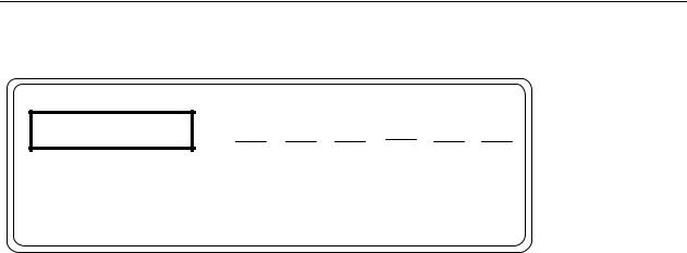
Figure 2-1. Front Panel Configuration
The Model 4000M+ features a 16-character dot matrix LCD display and six (6) rocker switches on the front panel, as shown in Figure 2-1. The following paragraphs summarize their functions.
Display
The 16-character dot matrix LCD displays the measurement results. The ROLL/RST Switch scrolls through the displayed values in the Radiographic Mode. In the Fluoroscopic Mode, displayed values are automatically toggled every two seconds.
In the Radiographic Mode, displayed values include:
•The average kVp
•The effective kVp
•The maximum kVp
•The length of the exposure in seconds
•The tube output in Roentgens or Grays
In the Fluoroscopic Mode, displayed values include:
•The real time exposure rate, in mR/min or mGy/sec
•The calculated kVp value
Tube output is displayed in user-selected quantities of Roentgens or Grays. Display units are factory preset according to the purchase order. The display units can be changed via an internal dip switch, located on the main PC Board. Use the following procedure:
1.Turn the Power Switch to OFF.
2.Place the unit upside down on a flat surface.
3.Remove the four screws (and feet) securing the case bottom to the case top.
4.Carefully remove the case bottom from the rest of the assembly.
5.Locate the four-position dip switch on the main PC board.
6.Set the first (1) position as follows:
•OFF to select Grays as the display units
•ON to select Roentgens as the display units.
2-2
Operation 2
Front Panel Configuration
NOTE
Switch positions 2, 3, and 4 have been factory set and MUST NOT be changed.
7.Carefully replace the case top.
8.Secure the case top to the rest assembly using the screws (and feet) removed in Step 3.
ON/OFF Switch
The ON/OFF Switch turns the instrument power on or off. As discussed earlier, the unit can be powered with either the internal rechargeable batteries or with AC line power using the supplied AC adapter.
NOTE
If an Invalid Filter message is displayed instead of the Filter Wheel setting, the Filter Wheel is set to CHK (or other illegal position) when the unit is turned ON in the RADIO or FLUORO modes.
If the RADIO/FLUORO Switch is set to RADIO, and the EXP/ALL Switch is set to ALL, a RADIO Ready message will be displayed.
If the RADIO/FLUORO Switch is set to FLUORO, and the EXP/ALL Switch is set to ALL, a FLUORO Ready message will be displayed followed by an exposure rate value (in mGy/sec or mR/min) and a calculated kVp value. The display will toggle between the exposure rate and kVp value.
NOTE
The display will show exposure rate only (rather than toggle between the exposure rate and calculated kVp value) in the event that the input to the detector is too low to provide an adequate signal for a kVp calculation.
RADIO/FLUORO Switch
The RADIO/FLUORO Switch selects either the Radiographic Measurement Mode or the Fluoroscopic Measurement Mode when the EXP/ALL Switch is set to ALL. When the EXP/ALL Switch is in EXP, the RADIO/FLUORO Switch selects either the DOSE or RATE mode. Refer to Section 3 – Theory of Operation for a discussion of applications for each mode.
NOTE
In the Fluoroscopic Mode, a real time display of tube output and kV are continuously updated. In the Radiographic Mode, data are accumulated until radiation ceases, and then the results are displayed.
EXP/ALL Switch
The EXP/ALL Switch selects the Ion Chamber Mode, either the Exposure Dose/Rate Mode (EXP) or the Radiographic/FLUORO Measurement Mode (ALL).
(W/Al)/(Mo/Mo) Switch
2-3
Victoreen 4000M+
Operators Manual
The (W/Al)/(Mo/Mo) Switch selects the target/filter of the X-Ray machine being used. Refer to Section 3
– Theory of Operation for a discussion of the applications for each setting.
HIGH/LOW Switch
The HIGH/LOW Switch selects the sensitivity of the detector. In the HIGH position, the kVp detector sensitivity is increased by a factor of 20, allowing compatibility with dental and mammography machines. The LOW position is suitable for most other applications.
NOTE
When the unit is in the Fluoroscopic Mode (FLUORO), the detector sensitivity is always high, regardless of the front panel HIGH/LOW Switch Setting.
ROLL/RST Switch
The ROLL/RST Switch, active only in the Radiographic Measurement and Exposure Modes, is a momentary contact rocker that allows the user to change the display mode to Auto Roll or Manual Roll and to scroll through measured quantities. The ROLL/RST Switch also zeros the display in the Exposure Dose Mode. On power up (and whenever the Sensitivity, Measurement Mode, or filter wheel selection is changed) the display mode defaults to Auto Roll.
NOTE
In the Fluoroscopic Mode, the display automatically toggles between the measured quantities. Values are updated every two seconds.
In the Auto Roll Mode, the display scrolls through the measured quantities one after the other, as if the ROLL button were being pressed once every two seconds. The display will continue to scroll until the ROLL button is pressed again.
When a Radiographic exposure is complete, the kVp average value is displayed. Other measured quantities can be displayed, one after another, by pressing the ROLL Switch to scroll through them. Holding the ROLL Switch for longer than two seconds forces the display to enter the Auto Roll Mode.
Use the following procedure to change the Display Mode:
1.If the current Display Mode is Auto Roll (i.e., the display values are changing every two seconds) and the unit is in the Radiographic Measurement Mode:
a.Press and release the ROLL Switch when the desired value is displayed (i.e., kVp Avg, kVp Eff, kVp Max, Sec, or mR). The Display Mode will change to Manual Roll. The selected value will remain displayed until ROLL is pressed again.
b.Perform Step 2 to scroll through the measured quantities, one after another.
2.If the current Display Mode is Manual Roll, press and hold the ROLL Switch for approximately two seconds. After “roll “ appears in the bottom right corner of the display, the Display Mode will change to Auto Roll. The display will be updated once every two seconds, scrolling through measured quantities one after the other.
When the ROLL/RST Switch is pressed to zero the exposure, the PLEASE WAIT message displays for approximately three seconds. The display will then read 0.0 mR or 0% Gy.
2-4

Operation 2
Rear Panel Configuration
2.4 Rear Panel Configuration
Power Supply/Charge Connector
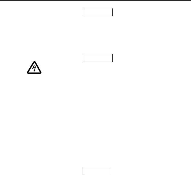
The Power Supply/Charge Connector for the AC Adapter is located on the rear panel and labeled POWER (see Figure 2-2). An AC adapter is supplied with each unit. The AC adapter supplies 9 volts, 500 mA power to the unit and recharges the internal batteries.
CAUTION
Use only the AC Adapter Supplied with the unit; other adapters may damage the unit.
Scope Connector
The Scope Connector is a BNC connector labeled SCOPE and located on the rear panel of the unit (see Figure 2-2). This connector allows the detector waveform to be displayed on a storage oscilloscope. It provides a voltage signal proportional to the radiation waveform as measured by the lightly filtered
BIAS SIGNAL |
kVp |
|
BEAM |
RANGE |
SCOPE POWER |
DIRECTION |
W/AI |
|
RS-232 |
|
|
detector.
Figure 2-2. Rear Panel Configuration
Filter Wheel
The filter wheel, located on the rear panel, allows selection of the kVp range. The wheel has six positions:
•27-42 (W/AI) or 21-50 (Mo/Mo)
•35-60
•50-85
•70-120
•CHK
•100-155
The numeric labels refer to the kVp range. The range associated with the position selected should conform to the kVp setting of the X-ray machine. The CHK position is used for a calibration check.
Beam Direction Arrow
The Beam Direction Arrow shows how the unit must be positioned to accept x-rays from the x-ray machine. For example, in the Fluoroscopic Mode, the unit must usually be turned upside down with the black plastic disk facing the x-ray tube.
2-5
Victoreen 4000M+
Operators Manual
NOTE
When the unit is upside down in the Fluoroscopic Mode, the display automatically inverts so it can be read from that position.
Ion Chamber Signal Connector
The Ion Chamber Signal Connector, labeled SIGNAL, is a BNC connector that accepts the input and signal from the external ion chamber.
CAUTION
An electrical shock hazard exists on the ion chamber bias (HV). Extreme care should be taken when in close proximity to the ion chamber bias.
Ion Chamber Bias Connector
The Ion Chamber Bias Connector, labeled BIAS, is a banana-type jack supplying 300 DC volts as bias supply for an external ion chamber.
RS-232 Port
The RS-232 Port is a 9-pin female connector configured as Data Communications Equipment (DCE). See Appendix B for more information on this port.
2.5 Detector Positioning
The detector must be positioned according to the type of measurement required. Section 3 – Theory of Operation includes a detailed discussion of detector positioning.
The following guidelines outline general detector positioning principles:
1. Locate the detector 46 to 102 centimeters (18 to 40 inches) away from the source of x-rays.
NOTE
The optimum source-to-detector distance (SDD) is 66 centimeters (26 inches) for most measurements. Refer to Appendix A for a discussion of source-to- detector distance.
2.The black plastic disk (on the top panel of the Model 4000M+) must point toward the source, and must be in the approximate center of the beam.
3.The beam must be parallel to, and in the same direction as, the BEAM DIRECTION arrow printed on the rear panel of the Model 4000M+.
4.To eliminate measurement error due to the ‘heel’ effect, position the Model 4000M+ so that the front-to-rear panel axis is parallel to the tube axis.
2-6

Operation 2
Calibration Check
2.6 Calibration Check
A calibration check should be performed periodically, or whenever a problem with the unit is suspected. Use the following procedure to perform a calibration check on the Model 4000M+:
1.Turn the Power Switch to ON. The Model No., software revision level, and filter setting will be displayed, followed by a FLUORO Ready or RADIO Ready indication, depending on the position of the FLUORO/RADIO Switch.
2.Position the Mode Selection Switch to RADIO.
3.Position the Sensitivity Selection Switch to LOW.
4.Rotate the filter wheel to the CHK position.
5.Position the detector as discussed in Section 3 – Theory of Operation.
6.Set the x-ray machine to 100 kV, 100 mA, and 100 msec.
7.Make an exposure.
8.At the end of the exposure, one of the following messages will be displayed:
a.CHK OK, indicating that the Model 4000M+ has passed the calibration check.
b.CHK Error LOW or CHK Error HIGH, indicating that the Model 4000M+ has NOT passed the calibration check. Repeat Steps 2 through 6.
If the unit continues to fail the calibration test, contact Fluke Biomedical at 440.248.9300 for further instructions.
2.7 Radiographic Measurements
Use the following procedure to make kVp, exposure, and time measurements with the Model 4000M+ in the Radiographic Mode:
1.Turn the Power Switch to ON. The Model No., software revision level, and filter setting will be displayed, followed by a FLUORO Ready or RADIO Ready indication, depending on the position of the FLUORO/RADIO Switch.
2.Position the Mode Selection Switch to RADIO.
3.Position the EXP/ALL Switch to ALL.
4.Position the Sensitivity Selection Switch to HIGH or LOW as required. (Refer to Sensitivity Selection in Section 3 – Theory of Operation.)
5.Position the Tube Target (Anode)/Filter Selection Switch to Mo/Mo or W/Al as required. (Refer to Tube Target (Anode)/Filter Selection in Section 3 – Theory of Operation.)
6.Rotate the filter wheel to the appropriate kVp setting, depending on the kVp setting of the X-Ray machine. The RADIO Ready indication should appear on the display.
NOTE
If there is a hardware failure, an ERROR message may be displayed instead of the RADIO Ready condition. Error message indications and meanings are discussed in Section 3 – Theory of Operation.
7.Position the detector as discussed in Section 3 – Theory of Operation.
8.Make an exposure.
2-7

Victoreen 4000M+
Operators Manual
9.At the end of the exposure, the value selected when the display was placed in the Manual Roll Mode will be displayed. If the selected value is Average kVp, the following will be displayed: XX.X kVp Avg
10.If the display is in Auto Roll Mode, the effective kVp maximum kVp, exposure time, and tube output will be displayed in sequence. The display will continue to scroll through the values, changing once every two seconds, until either:
a.Another exposure is made; when the exposure is complete, Analyzing... will be displayed. Values for the new exposure will then be displayed, automatically changing once every two seconds.
b.The ROLL/RST button is pressed and held until roll is displayed in the lower right corner of the display. This puts the display in the Manual Roll Mode. Go to Step 11.
NOTE
The default display mode is Auto Roll; i.e., on power up, when the Measurement Mode Switch is changed from FLUORO to RADIO, the sensitivity selection (HIGH/LOW) is changed, or the filter wheel is repositioned, the display will automatically go into the Auto Roll Mode.
11.If the display is in the Manual Roll Mode:
a.Press ROLL/RST. Assuming, from Step 9, that the Average kVp value is displayed, pressing ROLL will display the effective kVp as:
XX.X kVp Eff
b.Press ROLL/RST. The maximum kVp will be displayed as: XX.X kVp Max
c.Press ROLL/RST. The exposure time will be displayed as: XX.XX Sec
d.Press ROLL/RST. The tube output will be displayed as: XX.XX mR.
e.Press ROLL/RST. The average kVp will be displayed as: XX.X kVp Avg
f.Repeat Steps a through e as desired to scroll through the data.
g.Press and hold the ROLL/RST button for longer than two seconds to place the display in the Autoroll Mode. The display will continuously scroll through the measured quantities as if the ROLL/RST button were being pressed once every two seconds. Press ROLL/RST again to exit the Autoroll Mode.
12.Repeat Steps 3 through 11 as required.
NOTE
The Model 4000M+ is auto resetting; therefore, another exposure can be made at any time. At the end of each exposure, Analyzing... will appear on the screen. The updated values will automatically be displayed in the previously selected display mode (Auto Roll or Manual Roll).
2-8
Loading...