


 Loading...
®
79/26
Series III Multimeter
Instruction Sheet
WRead First: Safety Information
∙Never use the meter if the meter or test leads look damaged.
∙Be sure the test leads and switch are in the correct position for the desired measurement.
∙Never measure resistance in a circuit when power is applied.
∙Never touch the probe to a voltage source when the test leads are plugged into the 10 A or 40 mA input jack.
∙Never apply more than rated voltage between any input jack and earth ground.
∙Be careful when working with voltages above 60 V dc or 30 V ac rms. Such voltages pose a shock hazard.
∙Keep your fingers behind the finger guards on the test probes when making measurements.
WWarning
To avoid false readings, which could lead to possible electric shock or personal injury, replace the battery as soon as the battery indicator M appears.
Symbols
WRead First: Safety Information
YDangerous Voltage May Be Present
TDouble Insulation
Overvoltage Installation Category per IEC 1010:
CAT II |
Typical locations include main wall outlets, local |
|
appliances, and portable equipment. |
CAT III |
Typical locations include switches in the fixed |
|
installation and equipment for industrial use |
|
permanently connected to the fixed installation. |
PN 687589 August 1997 Rev. 2, 4/98
ã 1997, 1998 Fluke Corporation. All rights reserved. Printed in U.S.A. All product names are trademarks of their respective companies.
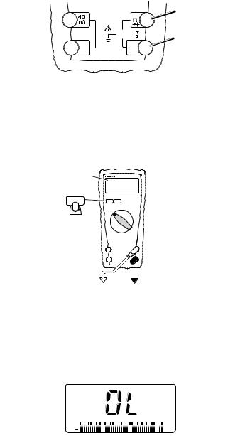
Input Jacks
Milliamp
Amp
Volts, Ohms,
V
Diode Test
600V |
CAT |
Common Terminal |
1000V |
CAT |


 FUSED
FUSED 

jo1f.eps
See Specifications for overload protection.
Ranging
The meter defaults to autorange when you turn on the meter.
Manual ranging is available in V ac, V dc, Hz, ohms, capacitance, A ac, and A dc.
MANUAL
MANUAL
RANGE
RANGE
Momentary
CAT 
CAT
+  _
_
jo11f.eps
To return to autorange, press 
 for 1 second or turn the rotary switch.
Bar Graph
The bar graph shows readings relative to the full scale value of the displayed measurement range and indicates polarity.
0 2001 400 2 600 3800 41000
+ |
mV |
|
jo19f.eps
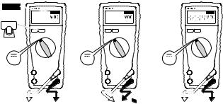
Automatic Touch Holdâ Mode
W Warning
To avoid electric shock, do not use the Touch Holdâ mode to determine if a circuit with high voltage is dead. The Touch Holdâ mode will not capture unstable or noisy readings.
The Touch Holdâ mode automatically captures and displays a stable voltage reading.
HOLD
HOLD |
HOLD |
HOLD |
RANGE |
RANGE |
RANGE |
V |
|
V |
|
V |
|
|
CAT |
|
CAT |
|
CAT |
|
|
|
CAT |
|
CAT |
+ |
_ |
+ |
_ |
+ |
_ |

 Single Beep
jo4f.eps
When the meter detects a new input, it beeps and displays a new reading.
Stray voltages can cause the meter to display a new reading.
To exit the Touch Holdâ mode, press the yellow key a second time or turn the rotary switch.
Smoothing Displayed Readings
Smoothing displays the average of eight readings. When the input signal changes rapidly, smoothing makes the digital display readings more stable. Smoothing does not work in continuity, LoOhms, and capacitance.
To select Smoothing, press the yellow key while turning on the meter.

Standby
If the meter is on but is inactive for an hour (20 minutes in diode test), the screen only displays four bar graph segments. To resume operation, turn the rotary switch or press a button.
AC and DC Voltage (K L mL)
|
Volts AC |
|
Volts DC |
Millivolts DC |
|
|
RANGE |
|
RANGE |
|
RANGE |
V |
|
V |
|
mV |
|
|
|
|
|
|
|
|
CAT |
|
CAT |
|
CAT |
|
|
|
CAT |
|
CAT |
+ |
_ |
+ |
_ |
+ |
_ |
jo3f.eps
In the mV dc function, the meter defaults to 400 mV. To enter the 40 mV range, press 
 momentarily.
Frequency (Hz)
The bar graph indicates the ac voltage present.
W Warning
To avoid electric shock, disregard the bar graph when frequency is > 1 kHz. If the frequency of the measured signal is > 1 kHz, the bar graph voltage is unspecified.


 Hz
Hz
+mV
RANGE
Hz
CAT 
CAT
+ _
_
jo20f.eps
Loading...