


®
2635A
Hydra Series II Data Bucket
Users Manual
PN 686698 November 1997
© 1997 Fluke Corporation, All rights reserved. Printed in U.S.A. All product names are trademarks of their respective companies.
LIMITED WARRANTY & LIMITATION OF LIABILITY
Each Fluke product is warranted to be free from defects in material and workmanship under normal use and service. The warranty period is one year and begins on the date of shipment. Parts, product repairs and services are warranted for 90 days. This warranty extends only to the original buyer or end-user customer of a Fluke authorized reseller, and does not apply to fuses, disposable batteries or to any product which, in Fluke’s opinion, has been misused, altered, neglected or damaged by accident or abnormal conditions of operation or handling. Fluke warrants that software will operate substantially in accordance with its functional specifications for 90 days and that it has been properly recorded on non-defective media. Fluke does not warrant that software will be error free or operate without interruption.
Fluke authorized resellers shall extend this warranty on new and unused products to end-user customers only but have no authority to extend a greater or different warranty on behalf of Fluke. Warranty support is available if product is purchased through a Fluke authorized sales outlet or Buyer has paid the applicable international price. Fluke reserves the right to invoice Buyer for importation costs of repair/replacement parts when product purchased in one country is submitted for repair in another country.
Fluke’s warranty obligation is limited, at Fluke’s option, to refund of the purchase price, free of charge repair, or replacement of a defective product which is returned to a Fluke authorized service center within the warranty period.
To obtain warranty service, contact your nearest Fluke authorized service center or send the product, with a description of the difficulty, postage and insurance prepaid (FOB Destination), to the nearest Fluke authorized service center. Fluke assumes no risk for damage in transit. Following warranty repair, the product will be returned to Buyer, transportation prepaid (FOB Destination). If Fluke determines that the failure was caused by misuse, alteration, accident or abnormal condition of operation or handling, Fluke will provide an estimate of repair costs and obtain authorization before commencing the work. Following repair, the product will be returned to the Buyer transportation prepaid and the Buyer will be billed for the repair and return transportation charges (FOB Shipping Point).
THIS WARRANTY IS BUYER’S SOLE AND EXCLUSIVE REMEDY AND IS IN LIEU OF ALL OTHER WARRANTIES, EXPRESS OR IMPLIED, INCLUDING BUT NOT LIMITED TO ANY IMPLIED WARRANTY OF MERCHANTABILITY OR FITNESS FOR A PARTICULAR PURPOSE. FLUKE SHALL NOT BE LIABLE FOR ANY SPECIAL, INDIRECT, INCIDENTAL OR CONSEQUENTIAL DAMAGES OR LOSSES, INCLUDING LOSS OF DATA, WHETHER ARISING FROM BREACH OF WARRANTY OR BASED ON CONTRACT, TORT, RELIANCE OR ANY OTHER THEORY.
Since some countries or states do not allow limitation of the term of an implied warranty, or exclusion or limitation of incidental or consequential damages, the limitations and exclusions of this warranty may not apply to every buyer. If any provision of this Warranty is held invalid or unenforceable by a court of competent jurisdiction, such holding will not affect the validity or enforceability of any other provision.
Fluke Corporation |
Fluke Europe B.V. |
P.O. Box 9090 |
P.O. Box 1186 |
Everett, WA 98206-9090 |
5602 BD Eindhoven |
U.S.A. |
The Netherlands |
5/94
Table of Contents
Chapter |
Title |
Page |
1 |
Preparation for Use............................................................................ |
1-1 |
|
Introduction ....................................................................................................... |
1-5 |
|
Operating Modes ............................................................................................... |
1-5 |
|
Front Panel Operation ................................................................................... |
1-7 |
|
Memory Card Operation ............................................................................... |
1-7 |
|
Computer Operation...................................................................................... |
1-8 |
|
Printer Operation........................................................................................... |
1-8 |
|
Modem Operation ......................................................................................... |
1-8 |
|
Measurement Capabilities ................................................................................. |
1-9 |
|
Mx+B Scaling ............................................................................................... |
1-9 |
|
Alarms ........................................................................................................... |
1-9 |
|
Totalizer Channel.......................................................................................... |
1-9 |
|
Alarm Outputs and Digital I/O...................................................................... |
1-9 |
|
Applications Software ....................................................................................... |
1-9 |
|
Hydra Starter Package................................................................................... |
1-10 |
|
Hydra Logger ................................................................................................ |
1-10 |
|
Options and Accessories ................................................................................... |
1-10 |
|
Memory Card Reader .................................................................................... |
1-10 |
|
Connector Set, 2620A-100............................................................................ |
1-10 |
|
Setting Up the Instrument.................................................................................. |
1-11 |
|
Unpacking and Inspecting the Instrument..................................................... |
1-11 |
|
Adjusting the Handle .................................................................................... |
1-12 |
|
Connecting the Instrument to a Power Source.............................................. |
1-12 |
|
AC Operation............................................................................................ |
1-13 |
|
DC Operation............................................................................................ |
1-13 |
|
Input Channels .............................................................................................. |
1-13 |
|
Measurement Connections ................................................................................ |
1-14 |
|
Using Shielded Wiring.................................................................................. |
1-14 |
|
Crosstalk........................................................................................................ |
1-14 |
|
Universal Input Module Connections ........................................................... |
1-14 |
|
Alarm Outputs Connections.......................................................................... |
1-17 |
|
DC Power.................................................................................................. |
1-17 |
|
Alarm Outputs .......................................................................................... |
1-17 |
|
External Trigger Input .............................................................................. |
1-17 |
|
Digital I/O Connections ................................................................................ |
1-18 |
i

2635A
Users Manual
|
Digital I/O ................................................................................................. |
1-18 |
|
Totalizer Input .......................................................................................... |
1-18 |
|
Controls and Indicators ..................................................................................... |
1-19 |
|
Front Panel Controls ..................................................................................... |
1-19 |
|
Front Panel Indicators ................................................................................... |
1-19 |
2 |
Front Panel Operations ..................................................................... |
2-1 |
|
Summary of Front Panel Operations ................................................................. |
2-5 |
|
Configuring the Instrument for Operation......................................................... |
2-6 |
|
Turning the Power on.................................................................................... |
2-6 |
|
Selecting a Channel....................................................................................... |
2-8 |
|
Configuring a Measurement Channel................................................................ |
2-8 |
|
Configuring a Channel to Measure DC Volts............................................... |
2-9 |
|
Configuring a Channel to Measure AC Volts............................................... |
2-10 |
|
Configuring a Channel to Measure Resistance ............................................. |
2-11 |
|
Configuring a Channel to Measure Frequency ............................................. |
2-12 |
|
Configuring a Channel to Measure Temperature.......................................... |
2-13 |
|
Thermocouples ......................................................................................... |
2-13 |
|
Resistance-Temperature Detectors ........................................................... |
2-13 |
|
Thermocouple Restrictions:...................................................................... |
2-13 |
|
Resistance Temperature Detectors Restrictions: ...................................... |
2-13 |
|
Configuring a Channel Off ........................................................................... |
2-16 |
|
Setting Operating Conditions ............................................................................ |
2-16 |
|
Setting the Scan Interval ............................................................................... |
2-17 |
|
Setting the Measurement Rate ...................................................................... |
2-18 |
|
Setting the Alarms......................................................................................... |
2-18 |
|
Alarm Indications While Scanning........................................................... |
2-18 |
|
Alarm Indications While Monitoring ....................................................... |
2-19 |
|
Alarm Indications While Reviewing ........................................................ |
2-19 |
|
Clearing Alarm Parameters from a Channel............................................. |
2-19 |
|
Alarm Outputs for Channel 0 to 3 Using the Alarm Outputs Connector . 2-19 |
|
|
Alarm Outputs for Channels 4 to 20 Using the Digital I/O Connector .... |
2-19 |
|
Alarms and Autoprinting .......................................................................... |
2-20 |
|
Alarms and Monitor-Alarm Triggering .................................................... |
2-20 |
|
Alarms and Mx+B Scaling ....................................................................... |
2-20 |
|
Setting the Mx+B Scaling ............................................................................. |
2-23 |
|
Examples................................................................................................... |
2-23 |
|
Restrictions ............................................................................................... |
2-23 |
|
Clearing Mx+B Scaling from a Channel .................................................. |
2-23 |
|
Operating Modes ............................................................................................... |
2-26 |
|
Using the Scan Mode .................................................................................... |
2-26 |
|
Memory Card as a Data Destination......................................................... |
2-26 |
|
Memory Card Formatting ......................................................................... |
2-26 |
|
Memory Card Capacity............................................................................. |
2-26 |
|
Memory Card Files ................................................................................... |
2-26 |
|
Memory Card Exchange During Scanning ............................................... |
2-26 |
|
Memory Card Data Extraction.................................................................. |
2-27 |
|
Memory Card Error Messages ...................................................................... |
2-28 |
|
Using the Monitor Mode............................................................................... |
2-29 |
|
Using the Review Mode................................................................................ |
2-30 |
|
Additional Features ........................................................................................... |
2-31 |
|
Scan Triggering Options ............................................................................... |
2-31 |
|
External Trigger........................................................................................ |
2-31 |
|
Monitor-Alarm Trigger............................................................................. |
2-31 |
ii
|
|
Contents (continued) |
|
Triggering Options and Memory Card Operation .................................... |
2-31 |
|
Totalizer Operation ....................................................................................... |
2-32 |
|
Digital Input/output Lines ............................................................................. |
2-33 |
|
Setting Date and Time................................................................................... |
2-34 |
|
Reading Instrument Software Versions ........................................................ |
2-35 |
|
Returning to the Local Mode ........................................................................ |
2-35 |
|
Front Panel Key Lockout Options ................................................................ |
2-36 |
|
Instrument Interfaces ......................................................................................... |
2-36 |
|
Memory Card Interface ................................................................................. |
2-36 |
|
RS-232 Computer Interface .......................................................................... |
2-37 |
|
Using the RS-232 Computer Interface With a Printer .................................. |
2-37 |
|
Using the RS-232 Computer Interface With a Modem................................. |
2-37 |
3 |
Memory Card Operations .................................................................. |
3-1 |
|
Summary of Memory Card Operations ............................................................. |
3-3 |
|
Memory Card Files ....................................................................................... |
3-3 |
|
Setup Files..................................................................................................... |
3-4 |
|
Data Files ...................................................................................................... |
3-4 |
|
Memory Card Capacity ................................................................................. |
3-4 |
|
Memory Card Battery ................................................................................... |
3-5 |
|
Inserting and Removing the Memory Card ....................................................... |
3-5 |
|
Inserting a Memory Card .............................................................................. |
3-5 |
|
Removing a Memory Card ............................................................................ |
3-5 |
|
Changing the Memory Card During Scanning.............................................. |
3-5 |
|
Setting the Memory Card Write-protect Feature .......................................... |
3-5 |
|
Installing or Replacing the Memory Card Battery ............................................ |
3-5 |
|
Initializing a Memory Card ............................................................................... |
3-7 |
|
Recording Measurement Results During Scanning........................................... |
3-8 |
|
Setup File Procedures........................................................................................ |
3-9 |
|
Using Setup Store.......................................................................................... |
3-9 |
|
Using Setup Load.......................................................................................... |
3-10 |
|
Using Setup Erase ......................................................................................... |
3-11 |
|
Data File Procedures ......................................................................................... |
3-12 |
|
Using Data Open ........................................................................................... |
3-12 |
|
Using Data Erase........................................................................................... |
3-13 |
|
Setup and Data Files Directory ......................................................................... |
3-14 |
|
Setup and Data File Current Status ................................................................... |
3-15 |
|
Memory Card File Operations to and from a PC .............................................. |
3-16 |
4 |
Computer Operations ........................................................................ |
4-1 |
|
Summary of Computer Operations.................................................................... |
4-3 |
|
Connecting the Instrument to a PC.................................................................... |
4-3 |
|
Configuring the Instrument for Computer Operations ...................................... |
4-5 |
|
Configuring the PC for Computer Operations .................................................. |
4-6 |
|
Testing the Instrument/PC RS-232 Interface .................................................... |
4-6 |
|
Testing the RS-232 Interface Using Terminal Emulation (Windows) ......... |
4-6 |
|
Testing the RS-232 Interface Using Terminal Emulation (Generic) ............ |
4-7 |
|
Testing the RS-232 Interface Using Gwbasic ............................................... |
4-9 |
|
Testing the RS-232 Interface Using Qbasic.................................................. |
4-10 |
|
Computer Interface Commands and Operation ................................................. |
4-12 |
|
How the Instrument Processes Input............................................................. |
4-12 |
|
Input Terminators.......................................................................................... |
4-12 |
|
Input String Examples................................................................................... |
4-13 |
|
Sending Numeric Values to the Instrument .................................................. |
4-13 |
iii

2635A
Users Manual
|
How the Instrument Processes Output .......................................................... |
4-13 |
|
Status Registers ............................................................................................. |
4-14 |
|
Instrument Event Register (IER) .............................................................. |
4-14 |
|
Standard Event Status Register (ESR)...................................................... |
4-16 |
|
Status Byte Register (STB)....................................................................... |
4-17 |
|
Computer Interface Command Set ................................................................ |
4-18 |
|
Xmodem File Transfers ................................................................................ |
4-18 |
5 |
Printer Operations ............................................................................. |
5-1 |
|
Summary of Printer Operations......................................................................... |
5-3 |
|
Connecting the Instrument to a Printer.............................................................. |
5-3 |
|
Configuring for Printer Operations ................................................................... |
5-5 |
|
Printing Measurement Data and Memory Card Directory ................................ |
5-6 |
|
Problems?...................................................................................................... |
5-6 |
|
Printing Measurement Results During Scanning .......................................... |
5-6 |
|
Printing the Review Array ............................................................................ |
5-8 |
|
Printing the Directory of the Memory Card.................................................. |
5-9 |
6 |
Modem Operations ............................................................................ |
6-1 |
|
Summary of Modem Operations ....................................................................... |
6-3 |
|
Connecting the Modem to a PC for Modem Configuration .............................. |
6-4 |
|
Configuring the Instrument Modem for Modem Operations ............................ |
6-4 |
|
Connecting the Modem to an Instrument .......................................................... |
6-6 |
|
Configuring the Instrument for Modem Operations.......................................... |
6-7 |
|
Testing the RS-232/Modem Interface ............................................................... |
6-8 |
7 |
Maintenance ....................................................................................... |
7-1 |
|
Introduction ....................................................................................................... |
7-3 |
|
Cleaning............................................................................................................. |
7-3 |
|
Line Fuse ........................................................................................................... |
7-3 |
|
Selftest Diagnostics and Error Codes................................................................ |
7-4 |
|
Performance Tests ............................................................................................. |
7-4 |
|
Accuracy Verification Test ........................................................................... |
7-7 |
|
Channel Integrity Test................................................................................... |
7-8 |
|
Thermocouple Measurement Range Accuracy Test ..................................... |
7-9 |
|
Four-Terminal Resistance Test ..................................................................... |
7-10 |
|
Thermocouple Temperature Accuracy Test.................................................. |
7-10 |
|
Open Thermocouple Response Test ............................................................. |
7-11 |
|
RTD Temperature Accuracy Test ................................................................. |
7-13 |
|
RTD Temperature Accuracy Test (Using Decade Resistance Source) .... |
7-13 |
|
RTD Temperature Accuracy Test (Using DIN/IEC 751 RTD) ................ |
7-14 |
|
Digital Input/Output Verification Tests ........................................................ |
7-15 |
|
Digital Output Test ................................................................................... |
7-15 |
|
Digital Input Test ...................................................................................... |
7-16 |
|
Totalizer Test ............................................................................................ |
7-17 |
|
Totalizer Sensitivity Test.......................................................................... |
7-18 |
|
Dedicated Alarm Output Test ....................................................................... |
7-18 |
|
External Trigger Input Test........................................................................... |
7-21 |
|
Calibration ......................................................................................................... |
7-21 |
|
Variations in the Display................................................................................... |
7-22 |
|
Service ............................................................................................................... |
7-22 |
iv

Contents (continued)
Appendices
A |
Specifications.............................................................................................. |
A-1 |
B |
Crosstalk Considerations ............................................................................ |
B-1 |
C |
Binary Upload of Logged Data................................................................... |
C-1 |
D |
RS-232 Cabling........................................................................................... |
D-1 |
E |
8-Bit Binary-Coded-Decimal Table............................................................ |
E-1 |
F |
Memory Card File Formats......................................................................... |
F-1 |
G |
True RMS Measurements ........................................................................... |
G-1 |
Index
v

2635A
Users Manual
vi
List of Tables
Table |
Title |
Page |
1-1. |
Data Bucket Features ............................................................................................. |
1-6 |
1-2. |
Options and Accessories........................................................................................ |
1-11 |
1-3. |
Front Panel Keys Description................................................................................ |
1-21 |
1-4. |
Annunciator Descriptions ...................................................................................... |
1-22 |
2-1. |
Configuration Reset (Default) Settings ................................................................. |
2-7 |
2-2. |
Selftest Error Codes............................................................................................... |
2-7 |
2-3. |
Thermocouple Ranges ........................................................................................... |
2-14 |
2-4. |
TLL Alarm Outputs (Channels 0 to 3) .................................................................. |
2-20 |
2-5. |
TTL Alarm Outputs (Channels 4 to 20) ................................................................ |
2-21 |
3-1. |
Memory Card Error Codes .................................................................................... |
3-6 |
4-1. |
Instrument Event Register (IER) ........................................................................... |
4-16 |
4-2. |
Event Status Register (ESR) .................................................................................. |
4-17 |
4-3. |
Status Byte Register (STB).................................................................................... |
4-18 |
4-4. |
Command and Query Summary............................................................................. |
4-19 |
4-5. |
Command and Query Reference ............................................................................ |
4-23 |
7-1. |
Power-Up Error Codes........................................................................................... |
7-4 |
7-2. |
Recommended Test Equipment ............................................................................. |
7-6 |
7-3. |
Performance Tests (Voltage, Resistance, and Frequency) .................................... |
7-7 |
7-4. |
Performance Tests for Thermocouple Temperature Function............................... |
7-11 |
7-5. |
Performance tests for RTD Temperature Function (Resistance Source)(ITS-90) |
7-14 |
7-6. |
Performance Tests for RTD Temperature Function (DIN/ IEC 751 |
|
|
Amendment 2)(ITS-90).......................................................................................... |
7-15 |
7-7. |
Digital Input Values............................................................................................... |
7-17 |
A-1. |
DC Voltage Measurements - Resolution ............................................................... |
A-2 |
A-2. |
DC Voltage Measurements - Accuracy ................................................................. |
A-2 |
A-3. |
AC Voltage Measurements - Resolution ............................................................... |
A-4 |
A-4. |
AC Voltage Measurements - Accuracy ................................................................. |
A-4 |
A-5. |
Temperature Measurements - Accuracy (Thermocouples) (IPTS-68) .................. |
A-5 |
A-6. |
Temperature Measurements - Accuracy (Thermocouples) (ITS-90) .................... |
A-6 |
A-7. |
Temperature Measurements - Accuracy (RTDs) (IEC751 Amendment 2) |
|
|
(ITS-90................................................................................................................... |
A-7 |
A-8. |
Temperature Measurements - Accuracy (RTDs) (IEC751 Amendment 1) |
|
|
(ITS-90) ................................................................................................................. |
A-7 |
A-9. |
Temperature Measurements - Accuracy (RTDs) (IEC751) (IPTS-68).................. |
A-8 |
A-10. |
AC Voltage Measurements - Resolution ............................................................... |
A-9 |
vii

2635A
Users Manual
A-11. |
AC Voltage Measurements - Accuracy ................................................................. |
A-9 |
A-12. |
AC Voltage Measurements.................................................................................... |
A-10 |
A-13. |
Resistance Measurements - Resolution. ................................................................ |
A-11 |
A-14. |
Resistance Measurements - Accuracy (Four-Wire)............................................... |
A-11 |
A-15. |
Frequency Measurements-Resolution and Accuracy ............................................ |
A-12 |
A-16. |
Frequency Measurements - Input Sensitivity ........................................................ |
A-12 |
A-17. |
Typical Scanning Rate ........................................................................................... |
A-13 |
A-18. |
Autoranging Rates ................................................................................................. |
A-14 |
C-1. |
Floating-Point Format............................................................................................ |
C-5 |
E-1. |
8-Bit Binary-Coded-Decimal ................................................................................. |
E-2 |
viii
List of Figures
Figure |
Title |
Page |
1-1. |
Data Bucket Front and Rear Panels ....................................................................... |
1-7 |
1-2. |
Typical Front Panel Display While Scanning ....................................................... |
1-8 |
1-3. |
Adjusting the Handle ............................................................................................. |
1-12 |
1-4. |
Connecting the Instrument to a Power Source....................................................... |
1-13 |
1-5. |
Universal Input Module Connections .................................................................... |
1-15 |
1-6. |
Two-Terminal and Four-Terminal Connections.................................................... |
1-16 |
1-7. |
ALARM OUTPUTS connector ............................................................................. |
1-17 |
1-8. |
DIGITAL I/O Connector ....................................................................................... |
1-18 |
1-9. |
Front Panel Keys.................................................................................................... |
1-19 |
1-10. |
Primary Display ..................................................................................................... |
1-19 |
1-11. |
Secondary Display ................................................................................................. |
1-20 |
1-12. |
Annunciator Display.............................................................................................. |
1-20 |
2-1. |
How to use the Control/Annunciator Diagrams .................................................... |
2-5 |
2-2. |
Turning the Power On ........................................................................................... |
2-6 |
2-3. |
Selecting a Channel ............................................................................................... |
2-8 |
2-4. |
Configuring a Channel to Measure DC Volts........................................................ |
2-10 |
2-5. |
Configuring a Channel to Measure AC Volts........................................................ |
2-11 |
2-6. |
Configuring a Channel to Measure Resistance...................................................... |
2-11 |
2-7. |
Configuring a Channel to Measure Frequency...................................................... |
2-12 |
2-8. |
Configuring a Channel to Measure Temperature (Thermocouples)...................... |
2-14 |
2-9. |
Configuring a Channel to Measure Temperature (RTDs) ..................................... |
2-15 |
2-10. |
Configuring a Channel Off .................................................................................... |
2-16 |
2-11. |
Setting the Scan Interval ........................................................................................ |
2-17 |
2-12. |
Setting the Measurement Rate ............................................................................... |
2-18 |
2-13. |
Setting the Alarms ................................................................................................. |
2-22 |
2-14. |
Setting the Mx+B Scaling...................................................................................... |
2-24 |
2-15. |
Using the Scan Mode............................................................................................. |
2-27 |
2-16. |
Memory Card Error Messages ............................................................................... |
2-28 |
2-17. |
Using the Monitor Mode ....................................................................................... |
2-29 |
2-18. |
Using the Review Mode ........................................................................................ |
2-30 |
2-19. |
Scan Triggering Options........................................................................................ |
2-32 |
2-20. |
Totalizer Operation................................................................................................ |
2-33 |
2-21. |
Setting Date and Time ........................................................................................... |
2-34 |
2-22. |
Reading Instrument Software Versions ................................................................. |
2-35 |
2-23. |
Returning to LOCAL Mode................................................................................... |
2-35 |
ix

2635A
Users Manual
2-24. |
Front Panel Key Lockout Options ......................................................................... |
2-36 |
3-1. |
Typical Memory Card............................................................................................ |
3-3 |
3-2. |
Front Panel Memory Card Percent Display........................................................... |
3-5 |
3-3. |
Initializing a Memory Card.................................................................................... |
3-7 |
3-4. |
Recording Measurement Results During Scanning ............................................... |
3-8 |
3-5. |
Using SETUP STORE to Save Configuration Files.............................................. |
3-9 |
3-6. |
Using SETUP LOAD to Load Configuration Files ............................................... |
3-10 |
3-7. |
Using SETUP ERASE to Delete Configuration Files ........................................... |
3-11 |
3-8. |
Using DATA OPEN to Save Measurement Data in a File .................................... |
3-12 |
3-9. |
Using DATA ERASE to Delete a Measurement Data File ................................... |
3-13 |
3-10. |
Using DIRECTORY to Examine SETUP and DATA files................................... |
3-14 |
3-11. |
Using STATUS to Examine SETUP and DATA Files.......................................... |
3-15 |
4-1. |
Connecting the Instrument to a PC ........................................................................ |
4-4 |
4-2. |
Configuring the Instrument for Computer Operations .......................................... |
4-5 |
4-3. |
Overview of Status and Event Data Registers ....................................................... |
4-15 |
4-4. |
Sample Program (GWBASIC)............................................................................... |
4-57 |
4-5. |
Sample Program (QBASIC)................................................................................... |
4-59 |
4-6. |
Sample Program (QuickC) (1of 5)......................................................................... |
4-62 |
5-1. |
Connecting the Instrument to a Printer .................................................................. |
5-4 |
5-2. |
Configuring the RS-232 Ports for Print Operations .............................................. |
5-5 |
5-3. |
Printing Measurement Results During Scanning................................................... |
5-7 |
5-4. |
Printing the Review Array ..................................................................................... |
5-8 |
5-5. |
Printing the Memory Card Directory..................................................................... |
5-10 |
6-1. |
Overall PC-to-Instrument Modem Connection...................................................... |
6-3 |
6-2. |
Connecting the Modem to a PC............................................................................. |
6-5 |
6-3. |
Connecting the Modem to an Instrument .............................................................. |
6-6 |
6-4. |
Configuring the Instrument RS-232 Port for Modem Operations ......................... |
6-7 |
7-1. |
Replacing the Line Fuse ........................................................................................ |
7-3 |
7-2. |
Four-Terminal Connections to 5700A................................................................... |
7-12 |
7-3. |
Four-Terminal Connections to Decade Resistance Box........................................ |
7-14 |
7-4. |
Dedicated Alarms Output Test .............................................................................. |
7-20 |
7-5. |
External Trigger Test............................................................................................. |
7-21 |
C-1. |
ASCII String Decoding.......................................................................................... |
C-3 |
C-2. |
Floating_Point Conversion .................................................................................... |
C-6 |
C-3. |
Example ................................................................................................................. |
C-8 |
D-1. |
Summary of RS-232 Connections ......................................................................... |
D-3 |
D-2. |
Hydra Series II (DB-9) to PC (DB-9) RS-232 Connection (Generic) ................... |
D-4 |
D-3. |
Hydra (DB-9) to PC (DB-25) RS-232 Connection................................................ |
D-5 |
D-4. |
Hydra Series II (DB-9 to Modem (DB-25) RS-232 Connection ........................... |
D-6 |
D-5. |
Hydra Series II (DB-9) to Printer (DB-25) RS-232 Connection ........................... |
D-7 |
D-6. |
RS-232 DB-9 and DB-25 Connectors.................................................................... |
D-8 |
G-1. |
Comparison of Common Waveforms .................................................................... |
G-2 |
x
CAUTION
THIS IS AN IEC SAFETY CLASS 1 PRODUCT. BEFORE USING, THE GROUND WIRE IN THE LINE CORD OR THE REAR PANEL BINDING POST MUST BE CONNECTED FOR SAFETY.
Interference Information
This equipment generates and uses radio frequency energy and if not installed and used in strict accordance with the manufacturer’s instructions, may cause interference to radio and television reception. It has been type tested and found to comply with the limits for a Class B computing device in accordance with the specifications of Part 15 of FCC Rules, which are designed to provide reasonable protection against such interference in a residential installation.
Operation is subject to the following two conditions:
∙This device may not cause harmful interference.
∙This device must accept any interference received, including interference that may cause undesired operation.
There is no guarantee that interference will not occur in a particular installation. If this equipment does cause interference to radio or television reception, which can be determined by turning the equipment off and on, the user is encouraged to try to correct the interference by one of more of the following measures:
∙Reorient the receiving antenna
∙Relocate the equipment with respect to the receiver
∙Move the equipment away from the receiver
∙Plug the equipment into a different outlet so that the computer and receiver are on different branch circuits
If necessary, the user should consult the dealer or an experienced radio/television technician for additional suggestions. The user may find the following booklet prepared by the Federal Communications Commission helpful: How to Identify and Resolve Radio-TV Interference Problems. This booklet is available from the U.S. Government Printing Office, Washington, D.C. 20402. Stock No. 004-000-00345-4.
Declaration of the Manufacturer or Importer
We hereby certify that the Fluke Model 2635A Data Bucket is in compliance with BMPT Vfg 243/1991 and is RFI suppressed. The normal operation of some equipment (e.g. signal generators) may be subject to specific restrictions. Please observe the notices in the users manual. The marketing and sales of the equipment was reported to the Central Office for Telecommunication Permits (BZT). The right to retest this equipment to verify compliance with the regulation was given to the BZT.
Bescheinigung des Herstellers/Importeurs
Hiermit wird bescheinigt, daβ Fluke Model 2635A Data Bucket in Übereinstimung mit den Bestimmungen der BMPT-AmtsblVfg 243/1991 funk-entstört ist. Der vorschriftsmäßige Betrieb mancher Geräte (z.B. Meßsender) kann allerdings gewissen Einschränkungen unterliegen. Beachten Sie deshalb die Hinweise in der Bedienungsanleitung. Dem Bundesamt für Zulassungen in der Telekcommunikation wurde das Inverkehrbringen dieses Gerätes angezeigt und die Berechtigung zur Überprüfung der Seire auf Einhaltung der Bestimmungen eingeräumt.
Fluke Corporation
xi

Safety Terms in this Manual
This instrument has been designed and tested in accordance with iec publication 1010, safety requirements for electrical measuring, control and laboratory equipment. This user manual contains information, warnings, and cautions that must be followed to ensure safe operation and to maintain the instrument in a safe condition. Use of this equipment in a manner not specified herein may impair the protection provided by the equipment.
The meter is designed for iec 664, installation category ii use. It is not designed for use in circuits rated over 4800va.
Warning statements identify conditions or practices that could result in personal injury or loss of life.
Caution statements identify conditions or practices that could result in damage to equipment.
Symbols Marked on Equipment
danger - high voltage.
ground (earth) terminal.
protective ground (earth) terminal. Must be connected to safety earth ground when the power cord is not used. See Chapter 2.
attention - refer to the manual. This symbol indicates that information about usage of a feature is contained in the manual. This symbol appears in the following two places on the instrument rear panel:
1.Ground binding post (left of line power connector). Refer to "Using External DC Power" in Chapter 2.
2.Alarm outputs/digital i/o connectors. Refer to Appendix A, Specifications.
Warning
To avoid electric shock:
∙When the input module is installed, consider all channels with connections as accessible terminals that may be hazardous live.
∙Disconnect the input module before touching or changing external wiring.
∙Remove inputs from live voltages before opening the input module.
xii

Contents (continued)
AC Power Source
The instrument is intended to operate from an ac power source that will not apply more than 264v ac rms between the supply conductors or between either supply conductor and ground. A protective ground connection by way of the grounding conductor in the power cord is required for safe operation.
DC Power Source
The instrument may also be operated from a 9 to 16v dc power source when either the rear panel ground binding post or the power cord grounding conductor is properly connected.
Use the Proper Fuse
To avoid fire hazard, use only a fuse identical in type, voltage rating, and current rating as specified on the rear panel fuse rating label.
Grounding the Instrument
The instrument utilizes controlled overvoltage techniques that require the instrument to be grounded whenever normal mode or common mode ac voltages or transient voltages may occur. The enclosure must be grounded through the grounding conductor of the power cord, or if operated on battery with the power cord unplugged, through the rear panel ground binding post.
Use the Proper Power Cord
Use only the power cord and connector appropriate for the voltage and plug configuration in your country.
Use only a power cord that is in good condition.
Refer cord and connector changes to qualified service personnel.
Do Not Operate in Explosive Atmospheres
To avoid explosion, do not operate the instrument in an atmosphere of explosive gas.
Do Not Remove Cover
To avoid personal injury or death, do not remove the instrument cover. Do not operate the instrument without the cover properly installed. Normal calibration is accomplished with the cover closed, and there are no user-serviceable parts inside the instrument, so there is no need for the operator to ever remove the cover. Access procedures and the warnings for such procedures are contained in the service manual. Service procedures are for qualified service personnel only.
Do Not Attempt to Operate if Protection may be Impaired
If the instrument appears damaged or operates abnormally, protection may be impaired. Do not attempt to operate it. When in doubt, have the instrument serviced.
xiii
Ten Minute Tour
Introduction
Note
This manual contains information and warnings that must be followed to ensure safe operation and keep the instrument in safe condition.
Data Bucket operation and operational features can be understood in about ten minutes by completing the following procedure. Prior to staring the procedure, connect the instrument to a power source (see Chapter 1) and connect the supplied test leads to the front panel jacks (Channel 0). Some steps terminate when you press the Ckey instead of the Ekey because the completed step is beyond the scope of this quick tour. However, all steps contain a figure reference in brackets [] for additional information. For example, the first step of applying power refers to [Figure 2-2], which describes three other ways of applying power (Configuration-Reset, Display-Hold, and Temperature-Toggle). Therefore, this procedure may be used for a quick instrument familiarization or as a basis for instrument applications.
It is assumed that the instrument is being powered for the first time or a configurationreset procedure cleared the instrument of configuration data. To apply a configurationreset to the instrument, hold down the Ckey when turning on the power and keep holding until the meter “beeps” in acknowledgment.
xiv
Ten Minute Tour (continued)
POWER
CH
20
...
10
...
0
SET FUNC
FUNC
OFF
°F [°C]
Hz
Ω
VAC
V DC
ENTER
SET FUNC
Auto
150.00 V
30.000 V
3.0000 V
300.00 mV
ENTER
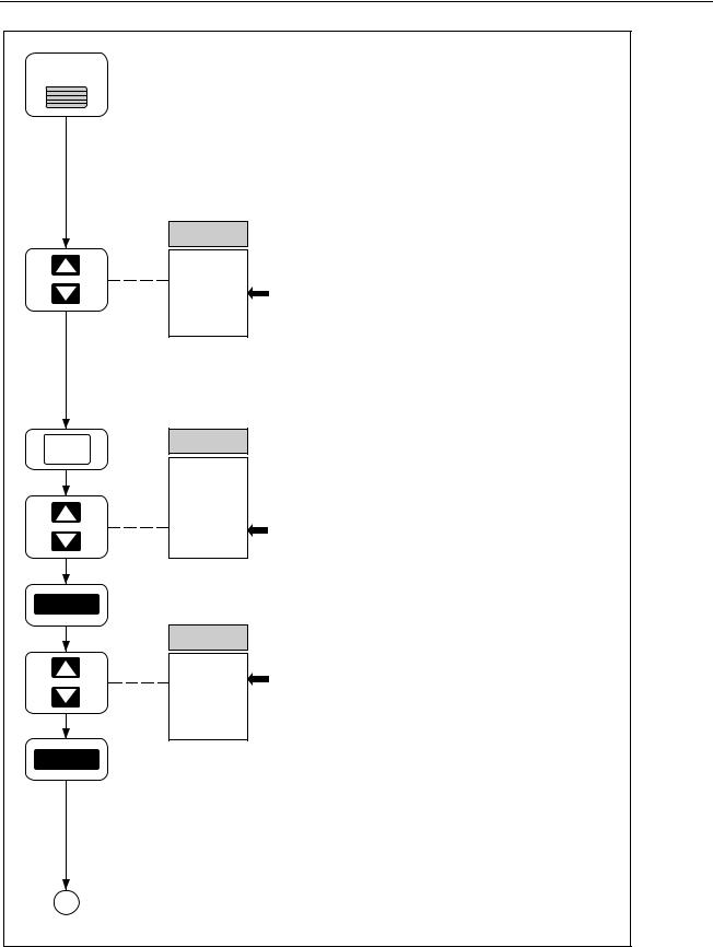
Applying power. Press the power switch to apply power. Other power-on options include Configuration-Reset, Display-Hold, and Temperature-Toggle. [Figure 2-2]
Selecting a Channel. Up/down arrow keys select a channel from 0 to 20. Channel 0 connections are on the front panel; Channels 1 through 20 connections are via the rear-panel Universal Input Module. Select Channel 10. [Figure 2-3]
Selecting a Function. Press the FUNC key to open the function menu. Up/down arrow keys select a function. Temperature unit °F/°C is set with the Temperature-Toggle Power-On procedure. Select VAC, then press ENTER. [Figure 2-5]
Selecting a Measurement Scale. Up/down arrow keys select a measurement scale. AUTO indicates autoranging, where the instrument automatically selects the scale that provides the best measurement resolution. Scale values are maximum expected readings, e.g., the 30.000 VAC scale is for measurements of 30 VAC or less. Select 150.00 V scale, then press ENTER. Channel 10 is now configured. [Figure 2-5]
A
op79_1f.eps
Ten Minute Tour
xv
2635A
Users Manual
A
FUNC
ENTER
ENTER
CH
20
...
10
...
0
SET FUNC
OFF
°F [°C]
Hz
Ω
VAC
V DC
SET FUNC
Auto 10.000 M 3.0000 M 300.00 k 30.000 k 3.0000 k 300.00
SET FUNC
2T
4T
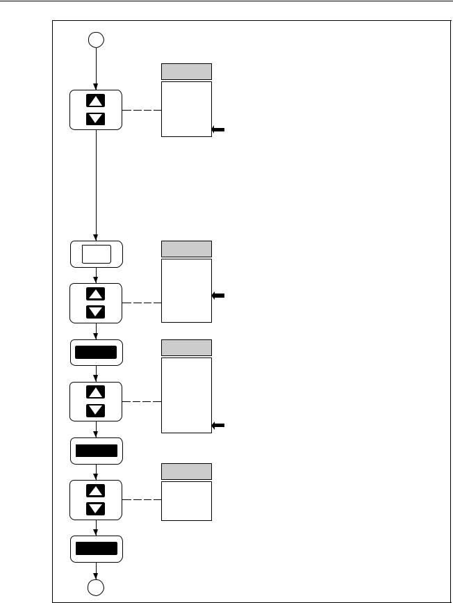
Selecting a Channel. Select Channel 0 with the up/down arrow keys. Notice each key entry is acknowledged with a short "beep." Try the left/right arrow keys and notice a long beep. Short beeps represent correct entries; long beeps represent incorrect entries. [Figure 2-3]
Selecting a Function. Press FUNC to open the function menu, use up/down arrow keys to select Ω, then press ENTER. [Figure 2-6]
Selecting a Measurement Scale. Select the 300.00 scale with up/down arrow keys, then press ENTER. [Figure 2-6]
Selecting a Terminal Configuration. Resistance measurements for channels 1 through 10 can use two channels (4 terminals) for increased precision. For channels 0 and 11 to 20, only 2 terminal (2T) connections are allowed. Press ENTER. [Figure 2-6]
ENTER
B
op79_2f.eps
Ten Minute Tour (cont)
xvi

Ten Minute Tour (continued)
B
MON
MON
0
10
MON
SCAN
0
SCAN
10
SCAN
SHIFT
SCAN
0
SCAN
10
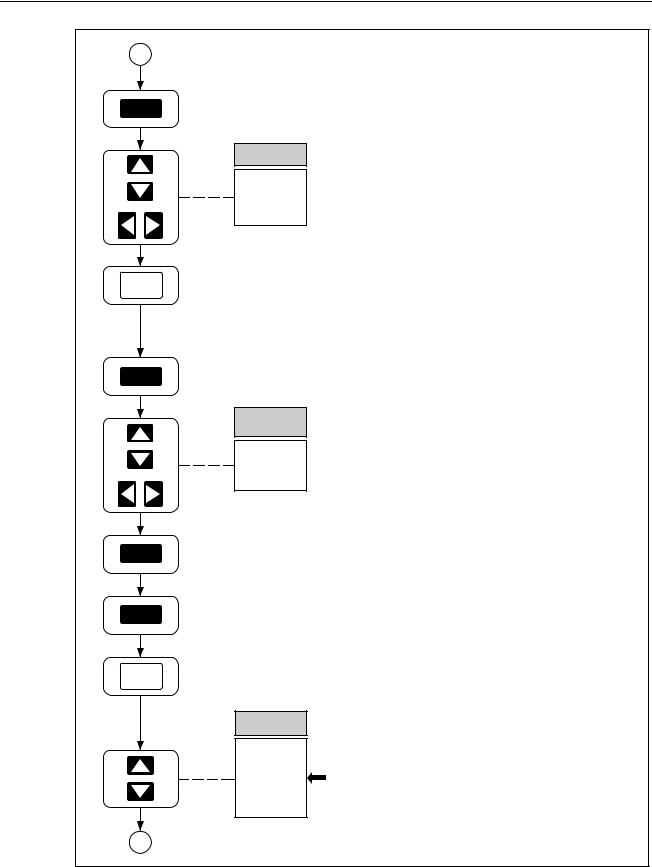
Selecting the Monitor Mode. Press the MON key to enable monitoring. Up/down arrow keys select any configured channel for monitoring. When Channel 0 (Ω) is selected, touch the probe tips together to measure test lead resistance. Channel 10 (VAC) may have a small reading because the input is unterminated. Press MON to exit monitoring. [Figure 2-17]
Selecting the SCAN Mode. Press the SCAN key to enable scanning. The display will indicate which channel is being measured during the scan. Monitor or Review can be enabled during scanning. Measurement data can be routed to the memory card, printer, or PC for display or processing. Press SCAN to exit scanning. [Figure 2-15]
Selecting the Single Scan Mode. Press the SHIFT key, release, then press the SCAN key to make a SINGLE measurement scan.
[Figure 2-15]
C
op79_3f.eps
Ten Minute Tour (cont)
xvii
2635A
Users Manual
C
INTVL
SET
0:00:00
CANCL
REVIEW
REVIEW
LAST MIN MAX
0
10
SHIFT
REVIEW
CANCL
CH
20
...
10
...
0
Setting the Scan Interval. Press the INTVL key to open the interval menu. Up/down and left/right arrow keys select 0:00:00 (default) to 9:99:99. The format is HOURS:MINUTES:SECONDS. The scan interval is the total time between the start of each measurement cycle. 0:00:00 represents continuous scanning. Press CANCL to exit. [Figure 2-11]
Selecting the Review Mode. Press the REVIEW key to open the Review array. The Review array holds the last, maximum, and minimum readings during all previous scans for all configured channels. Up/down arrow keys select the channel, while left/right arrow keys select LAST, MAX, and MIN. To CLEAR the Review array, press the SHIFT key, release, then press the REVIEW key. The Review array is cleared automatically by changing any parameter on any channel (including Measurement Rate). Press CANCL to exit. [Figure 2-18]
Select Channel 10. Select Channel 10 with the up/down arrow keys. [Figure 2-3]
D
op79_4f.eps
Ten Minute Tour (cont)
xviii
Ten Minute Tour (continued)
D
ALRM
SET ALARM
1
2
CANCL
Mx+B
SET Mx+B
M
+001.00
CANCL
SHIFT
RAtE
FASt
SLO
CANCL
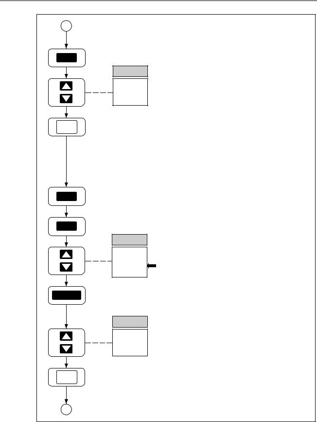
Selecting Alarms. Press the ALRM key to open the alarm menu. Each configured channel can have two alarm limits assigned. An alarm is set when a reading is below or above an alarm limit. Configuration starts with an alarm limit selection, 1 or 2. Press CANCL to exit. [Figure 2-13]
Setting Mx+B Scaling. Press the Mx+B key to open the Mx+B menu. Up/down and left/right arrow keys select the digits for the first parameter
(M) (default +001.00). The effect of Mx+B scaling is to take a measurement (x) and modify it by multiplying the measurement with M and then adding an offset B (configured after M is set). For example, Mx+B=+1.5x+25 applied to a measurement of 20.000 would display 1.5(20.000) + 25 = 55.000. Press CANCL to exit. [Figure 2-14]
Selecting the Measurement Rate. Press the SHIFT key, release, then press the Right Arrow key to open the RATE menu. During the measurement portion of the scan interval, the measurement rate can be FASt (Fast) or SLO (Slow). The slow rate gives full 5-digit measurement resolution, while the fast rate gives only 4-digit resolution. The advantage of a fast measurement rate is more readings during continuous scanning or low scan intervals. Press CANCL to exit. [Figure 2-12]
E
op79_5f.eps
Ten Minute Tour (cont)
xix

2635A
Users Manual
E
SHIFT
INTVL
yEAR
94
CANCL
totAL
TOTAL |
0 |
SHIFT
Setting Date and Time. Press the SHIFT key, release, then press the INTVL key to open the date and time (CLOCK) menu. Up/down and left/right arrow keys select the YEAR 00 to 99. For the complete procedure, this is followed by MONTH:DAY and HOURS:MINUTES. Press CANCL to exit. [Figure 2-21]
Selecting the Totalizer Feature. Press the TOTAL key to open the totalizer display. The totalizer operates independently as a separate instrument function. Contact closures or voltage transitions between pins Σ and  on the rear panel DIGITAL I/O connector are totaled and displayed by pressing the TOTAL key. To ZERO the total (already 0 in this example), press the SHIFT key, release, then press the TOTAL key again. Press CANCL to exit. [Figure 2-20]
TOTAL
CANCL
F
op79_6f.eps
Ten Minute Tour (cont)
xx

Ten Minute Tour (continued)
F
SHIFT
MON
tRIg
ALAr
On
OFF
CANCL
Selecting Triggering Options. Press the SHIFT key, release, then press the MON key to open the TRIGS option menu. A trigger option can trigger scanning, instead of using the SCAN key. OFF indicates no triggering option; ON indicates the external trigger option is active (a contact closure or voltage transition between pins TR and on the rear panel ALARM OUTPUTS connector); ALAr (Alarm) indicates scan triggering when a monitored channel goes into Alarm. Press CANCL to exit. [Figure 2-19]
SHIFT
LIST
bAUd
38400
...
300
CANCL
Setting the Communication Parameters. Press the SHIFT key, release, then press the LIST key to open the COMM menu. The communication parameters configure the rearpanel RS-232 interface for printer and PC operations. The first selection is bAUd (Baud) with rates from 300 to 38400 baud. For the complete procedure, this is followed by parity, flow control and echo. Press CANCL to exit. [Figure 5-2]
G
op79_7f.eps
Ten Minute Tour (cont)
xxi
2635A
Users Manual
G
LIST
LISt
dir
LASt
CANCL
SHIFT
FILES
dESt
both Print CArd nonE
ENTER
MODE
trAnS ALAr ALL
CANCL
Setting the LIST Parameters. Press the LIST key to open the LIST menu. LIST is used to print out all the measurements from the Review Array, or print out a directory of all the files on the memory card by selecting dir (Directory). To use LIST, a printer (or PC) must be connected to the RS-232 port. Press CANCL to exit. [Figure 5-4]
Setting the DESTINATION Parameter. Press the SHIFT key, release, then press the FILES key to open the MODE menu. CArd (Card) routes data to the memory card; Print (Print) routes data to the RS-232 connector to a printer (or PC); both (Both) routes data to both destinations, and nonE (None) to neither destination. Select CArd and press ENTER. [Figure 5-3]
Selecting the Destination Mode. ALL (All) sends all measurement data to the destination device (Memory Card in this example); ALAr (Alarm) send all measurement data to the destination device when any scanned channel is in alarm; trAnS (Transition) sends all measurement data to the destination device when any scanned channel transitions into or out of an alarm condition. Press CANCL to exit. [Figure 5-3]
H
op79_8f.eps
Ten Minute Tour (cont)
xxii

Ten Minute Tour (continued)
H
FILES |
|
Selecting the File Options. |
Press the FILES |
|
|
|
FILES |
||
|
|
key to open the Files menu. This menu selects |
||
|
|
|
||
|
|
|
||
|
|
Init |
the memory card functions. |
SEtUP (Setup) |
|
|
StAt |
selects card functions for instrument |
|
|
|
dir |
configuration files (SEtxx); dAtA (Data) selects |
|
|
|
|||
|
|
dAtA |
card functions for measurement data files |
|
|
|
SEtUP |
(dAtxx); dir (Directory) lists the number of |
|
|
|
|
kilobytes free on the card and the name and size |
|
|
|
|
||
|
|
|
of each SEtxx and dAtxx file; StAt (Status) lists |
|
CANCL |
which SEtxx and dAtxx files are currently active |
|||
|
|
|
and percentage of the card that is used; Init |
|
|
|
|
(Initialize) formats a blank card or erases and |
|
|
|
|
formats a used card. Press CANCL to exit. |
|
|
|
|
[Figure 3-3] |
|
|
|
|
|
|
|
|
|
|
op79_9f.eps |
|
|
|
Ten Minute Tour (cont) |
|
xxiii

2635A
Users Manual
xxiv
Chapter 1
Preparation for Use
Title |
Page |
Introduction ....................................................................................................... |
1-5 |
Operating Modes ............................................................................................... |
1-5 |
Front Panel Operation ................................................................................... |
1-7 |
Memory Card Operation ............................................................................... |
1-7 |
Computer Operation...................................................................................... |
1-8 |
Printer Operation........................................................................................... |
1-8 |
Modem Operation ......................................................................................... |
1-8 |
Measurement Capabilities ................................................................................. |
1-9 |
Mx+B Scaling ............................................................................................... |
1-9 |
Alarms ........................................................................................................... |
1-9 |
Totalizer Channel.......................................................................................... |
1-9 |
Alarm Outputs and Digital I/O...................................................................... |
1-9 |
Applications Software ....................................................................................... |
1-9 |
Hydra Starter Package................................................................................... |
1-10 |
Hydra Logger ................................................................................................ |
1-10 |
Options and Accessories ................................................................................... |
1-10 |
Memory Card Reader .................................................................................... |
1-10 |
Connector Set, 2620A-100............................................................................ |
1-10 |
Setting Up the Instrument.................................................................................. |
1-11 |
Unpacking and Inspecting the Instrument..................................................... |
1-11 |
Adjusting the Handle .................................................................................... |
1-12 |
Connecting the Instrument to a Power Source.............................................. |
1-12 |
AC Operation............................................................................................ |
1-13 |
DC Operation............................................................................................ |
1-13 |
Input Channels .............................................................................................. |
1-13 |
Measurement Connections ................................................................................ |
1-14 |
Using Shielded Wiring.................................................................................. |
1-14 |
Crosstalk........................................................................................................ |
1-14 |
Universal Input Module Connections ........................................................... |
1-14 |
Alarm Outputs Connections.......................................................................... |
1-17 |
DC Power.................................................................................................. |
1-17 |
Alarm Outputs .......................................................................................... |
1-17 |
External Trigger Input .............................................................................. |
1-17 |
Digital I/O Connections ................................................................................ |
1-18 |
Digital I/O ................................................................................................. |
1-18 |
1-1

2635A
Users Manual
Totalizer Input .......................................................................................... |
1-18 |
Controls and Indicators ..................................................................................... |
1-19 |
Front Panel Controls ..................................................................................... |
1-19 |
Front Panel Indicators ................................................................................... |
1-19 |
1-2

Preparation for Use 1
Introduction
1-3

2635A
Users Manual
HYDRA |
SERIES II |
REVIEW |
|
|
|
|
|
|
LAST |
mA |
|
|
CH |
|
|
|
|
|
|
|
|||
|
|
mVDCAC |
|
|
|
|
|
|
|
Mk |
Hz |
|
|
|
|
COM |
V |
|
|
|
|
|
|
|
|
|
|
|
|
|
|
|
|
|
|
INTVL |
FILES |
REVIEW |
SCAN |
|
|
|
|
CLEAR |
|||
|
FUNC |
ALRM |
|
CLOCK |
MODE |
|
|
|
|
|
SINGLE |
||||
|
|
|
|
|
|||
|
300V |
|
RATE |
|
|
|
|
|
MAX |
|
|
|
|
|
MON |
|
|
ENTER |
|
|
|
||
|
Mx+B |
SHIFT |
LIST |
TOTAL |
|
||
|
CANCEL |
|
LOCAL |
COMM |
ZERO |
TRIGS |
|
|
|
|
|
|
|
||
|
|
|
|
BUSY BATT |
|
|
|
|
|
|
|
|
|
|
OP80F.EPS |
1-4
 Loading...