


 Loading...
601PROXL International Safety Analyzer
Operators Manual
ENT
|
|
|
|
|
|
|
|
|
|
|
|
PREVIOUS |
|
|
|
|
|
|
|
|
|
|
|
|
|
|
|
|
|
P |
|
|
|
|
|
ANALYZER |
|
|
|
|
|
|
|
ESC/STO |
PRESENT |
||
|
|
|
|
|
|
|
|
|
|
|
|
||||
|
|
|
XL |
|
|
|
|
|
|
|
|
|
|
|
SETTINGS |
|
|
|
SAFETY |
|
|
|
|
|
|
|
|
|
|
|
|
|
Series |
|
|
|
|
SUPPLY |
PART |
|
|
|
|||||
INTERNATIONAL |
|
EARTH |
|
|
|
|
|||||||||
Pro |
|
|
|
|
|
|
|
|
|
|
|
|
|||
601 |
|
|
PROTECTIVE INSULATIONER |
APPLIED PART |
|
|
|||||||||
|
|
|
|
|
|
|
|
|
|
||||||
|
|
|
|
DOUBLE |
POW |
|
|
|
|||||||
|
I |
|
|
|
INTERNAL |
|
|
|
APPLIED |
PART |
|
|
|||
|
|
|
|
|
|
N |
|
|
|
|
APPLICATION |
|
|||
CLASS |
|
|
|
|
|
-ISOLATED |
APPLIED |
|
|
|
|||||
|
II |
|
|
|
NO |
ISOLATED |
|
DEVICE |
|
||||||
CLASS |
|
IP |
|
|
|
CARDIAC |
|
||||||||
|
CLASS |
B |
|
|
|
|
ISOLATED |
DEVICE |
|
|
|||||
|
|
CF |
|
|
|
DIRECT |
TRANSPORTABLE |
|
|||||||
|
|
|
TYPE |
|
|
|
|
|
|
||||||
|
|
TYPE |
BF |
|
|
|
|
|
FIXED |
|
|
|
|
||
|
|
|
|
|
|
|
|
|
|
|
|
|
|||
|
|
|
|
TYPE |
F |
|
|
|
|
|
|
|
|
|
|
|
|
|
|
|
TYPE |
T |
|
|
|
|
|
|
|
|
|
|
|
|
|
|
|
TYPE |
|
|
|
|
|
|
|
|
|
|
|
|
|
|
|
-M |
|
|
|
|
|
|
|
|
|
|
|
INSULATION2 |
|
|
|
|
|
|
|
|
|
|
|
|
|
ENCLOSURE |
|
|
|
|||
|
|
|
|
|
|
|
|
|
-µA |
|
|
|
|
|
TESTS |
-A |
|
|
|
LEAKAGE5 |
AUXILIARY |
||||
|
|
CURRENT |
|
|
|
|
|
PATIENT |
-µA |
|
||
|
|
|
1 |
|
|
|
|
|
CURRENT8 |
EQUIVALENLEAKT |
||
|
|
|
|
-µA |
|
|
|
|
|
|
|
-µA |
|
|
|
EARTHKAGE4 |
|
AP |
|
|
|
|
|
PATIENT |
|
|
|
|
LEA |
|
|
|
|
|
|
|
||
-V |
|
|
|
ON -µA |
|
|
|
|
VDE |
|||
|
EARTH |
|
|
|
|
|
|
|
|
|||
VO |
0 |
|
MAINS |
|
|
|
|
|
|
|
||
LTS |
|
|
|
LEAKAGE7 |
UIVALENT |
|
|
|
||||
|
|
- |
|
|
|
|
|
|||||
|
PROTECTIVE3 |
|
|
|
|
|
|
|
||||
|
|
RESISTANCE |
|
|
|
VDE |
|
-µA |
|
|
|
|
|
|
|
|
|
|
/ |
|
|
|
|||
|
|
|
|
|
|
|
EQ |
LEAK |
|
|
|
|
|
|
|
-µA |
|
|
|
DEVICE |
|
|
|
|
|
|
|
PATIENT |
|
|
|
|
|
|
|
|
|
|
|
|
LEAKAGE6 |
-V/µA |
|
|
|
|
|
|
|
||
|
|
|
ACCESSIBLE |
|
|
|
|
|
|
|
|
|
|
|
|
1010 |
|
|
|
|
|
|
|
|
|
|
|
|
IEC |
9 |
|
|
|
|
|
|
|
|
HEADER |
|
|
|
|
|
|
|
|
|
|
|
|
|
|
|
|
|
|
|
|
|
|
|
|
|
|
DATA |
|
|
|
|
|
|
|
|
|
|
|
INT |
|
|
|
|
|
|
|
|
|
|
|
|
PR |
|
|
|
|
|
|
|
|
|
|
|
|
baw151f.eps
PN 2234222
April 2005
2005 Fluke Corporation, All rights reserved. Printed in USA. All product names are trademarks of their respective companies.

N O T I C E S , W A R N I N G S A N D C O N T E N T
Notices
Fluke Biomedical
A Division of Fluke Electronics
6920 Seaway Blvd.
Everett, WA 98203
USA
Customer Service and Sales
USA and Canada: |
800.648.7952 |
Outside the USA: |
775.883.3400 |
Sales E-Mail: |
sales@flukebiomedical.com |
Internet: |
www.flukebiomedical.com |
Service: |
888.993.5853 |
Outside the USA: |
425.446.5560 |
For additional sales or service information, contact your local Fluke Biomedical Distributor or Fluke Electronics office
References in this manual to Bio-Tek Instruments, Inc. and DNI Nevada, refer to companies that are now part of Fluke Biomedical.
All Rights Reserved
Copyright © 2005, Fluke Biomedical. All rights are reserved. No part of this manual may be reproduced, transmitted, transcribed, stored in a retrieval system, translated into any language, or transmitted in any form or by any means electronic or mechanical, including photocopying and recording, for any purpose other than the purchaser's personal use without written permission of Fluke Biomedical.
Manufacturing location
Fluke Biomedical
6920 Seaway Blvd Everett, WA 98203 USA 775-883-3400 800-648-7952
Trademarks
IBM®, PC® and PC/AT® are registered trademarks of International Business Machines Corporation.
Microsoft® and MS-DOS® are registered trademarks of Microsoft Corporation.
Restrictions and Liabilities
Information in this document is subject to change and does not represent a commitment by Fluke Biomedical. Changes made to the information in this document will be incorporated in new editions of the publication.
No responsibility is assumed by Fluke Biomedical Corporation for the use or reliability of software or equipment that is not supplied by Fluke Biomedical Corporation or its affiliated dealers.
i i i

6 0 1 P R O S E R I E S X L
Warnings
Use of this instrument is restricted to qualified personnel who recognize shock hazards and are familiar with safety precautions used when operating electrical equipment. Read the manual carefully before operating the 601PRO.
The following warning and informational symbols can be found on the 601PRO:
Symbol |
Description |
|||
|
|
|
|
Caution: Risk of electric shock |
|
|
|
|
|
|
|
|
|
Direct / Alternating Current |
|
|
|
|
|
|
|
|
|
|
|
|
|
|
Protective Earth (PE) |
|
|
|
|
|
|
|
|
|
|
|
|
|
|
Caution: Refer to accompanying |
|
|
|
|
|
|
|
|
|
|
|
|
|
|
documentation |
|
|
|
|
Off (power: disconnection from Mains) |
|
|
|
|
|
|
|
|
|
|
|
|
|
|
On (Power: connection to Mains) |
|
|
|
|
|
|
|
|
|
|
|
|
|
|
Equipotential/Functional Earth (FE) |
|
|
|
|
|
|
|
|
|
|
|
|
|
|
|
i v

N O T I C E S , W A R N I N G S A N D C O N T E N T
Exercise extreme caution when a shock hazard is present at the instrument's measurement terminals during the following tests:
•Mains on Applied Part
•Mains on Applied Part Calibration
•Protective Earth Resistance
•Protective Earth Resistance Calibration
•Equivalent Patient Leakage
•Equivalent Device Leakage
•Equivalent Device/Patient Leakage Calibration
FOR CORRECT OPERATION, ALL GROUND-REFERENCED PERIPHERALS, SUCH AS PRINTERS AND PCs, MUST BE DISCONNECTED.
Do not discharge a defibrillator while it is plugged into the 601PRO.
Only use Fluke Biomedical-supplied test leads or leads rated for 32 Amps/1000 Volts with the Protective Earth Resistance Test.
Inspect the lead ends for possible wear, cracks or breaks before each use.
Take leakage current measurements only after earth resistance is measured and found to be compliant with the applied safety limit.
External devices, such as printers and computers, attached to the 601PRO, may affect the 601PRO's ability to sense Open Earth conditions on the Mains input. If Mains voltage readings are in error, remove all external devices.
If the DUT fails the Earth Resistance test, the operator must discontinue testing and label the DUT defective.
If any single test fails, the test must be immediately discontinued and the DUT labeled defective.
Prior to performing an ECG Simulation test, perform an Applied Part Leakage Test. If the Applied Part Leakage Test yields an instrument-under-test failure, then do not perform an ECG Simulation Test, as damage to the instrument may occur.
If operating the 601PRO with a variable AC Supply (Variac), it is important to perform a calibration after changing the Mains Voltage level. Calibration can be performed from within the Mains On Applied Part, Equivalent Device Leakage, or Equivalent Patient Leakage tests.
v

6 0 1 P R O S E R I E S X L
Nomenclature
Comparable Terminology: International and United States
INTERNATIONAL/IEC |
U.S./AAMI |
L1 |
Hot |
L2 |
Neutral |
Earth |
Ground |
Mains |
Line Voltage |
Applied Parts |
Patient Leads |
Enclosure/Case |
Chassis |
Protective Earth |
Ground Wire |
Earth Leakage Current |
Leakage in Ground Wire |
Enclosure Leakage |
Chassis Leakage |
Patient Leakage |
Lead Leakage |
Patient Auxiliary |
Leakage between Patient Leads |
Mains on Applied Parts |
Lead Isolation |
Insulation Resistance |
Dielectric Strength or |
|
Insulation Resistance between |
|
Hot and Neutral to Ground |
Earth Resistance |
Ground Wire Resistance |
v i

N O T I C E S , W A R N I N G S A N D C O N T E N T
Hazard Warnings
Warning! Power Rating. The 601PRO's mains power input must be connected to a power receptacle that provides voltage within the specified rating for the system. Connection must be made via the Mains Power cord provided by Fluke Biomedical.
Use of an incompatible power receptacle or incorrect Mains Power cord may produce electrical shock and fire hazards. Acceptable Mains Voltage ranges are 90~VAC to 132~VAC, and 180~VAC to 240~VAC 50/60 Hz. The current ratings for the 601PRO are as follows:
Europe: |
<=15A (Fused by 15A circuit breaker) |
United Kingdom: |
<=13A (Fused by 13A fused Mains Power Cord) |
Australia: |
<=10A (Fused by 10A circuit breaker) |
Warning! Internal Voltage. Always turn off the power switch and unplug the power cord before cleaning the 601PRO's outer surface.
Warning! Liquids. Avoid spilling liquids on the analyzer; fluid seepage into internal components creates a potential shock hazard. Do not operate the instrument if internal components are exposed to fluid.
Precautions
The following precautions are provided to help you avoid damaging the system:
To power up the 601PRO, place the index finger on the rocker switch and use a rolling motion to push from "OFF" to "ON." Do NOT forcefully push or snap the rocker switch. This may cause the unit to shut off.
Caution: Service. The 601PRO should be serviced by authorized service personnel. Only qualified technical personnel should perform troubleshooting and service procedures on internal components.
Caution: Environmental Conditions. Do not expose the system to temperature extremes. Ambient temperatures should remain between 18-40°C. System performance may be adversely affected if temperatures fluctuate above or below this range.
Caution: Do Not Immerse. Clean only with a mild detergent, and wipe down with a gentle cloth.
v i i

6 0 1 P R O S E R I E S X L
Electromagnetic Interference and Susceptibility
USA FCC CLASS A
Warning: Changes or modifications to this unit not expressly approved by the manufacturer could void the user's authority to operate the equipment.
This equipment has been tested and found to comply with the limits for a Class A digital device, pursuant to Part 15 of the FCC Rules.
These limits are designed to provide reasonable protection against harmful interference when the equipment is operated in a commercial environment. Like all similar equipment, this equipment generates, uses, and can radiate radio frequency energy and, if not installed and used in accordance with the instruction manual, may cause harmful interference to radio communications. Operation of this equipment in a residential area is likely to cause interference, in which case the user will be required to correct the interference at his own expense.
Canadian Department of Communications Class A
This digital apparatus does not exceed Class A limits for radio emissions from digital apparatus set out in the Radio Interference Regulations of the Canadian Department of Communications.
Le present appareil numerique n'met pas du bruits radioelectriques depassant les limites applicables aux appareils numerique de la Class A prescrites dans le Reglement sur le brouillage radioelectrique edicte par le ministere des Communications du Canada.
User Safety
This device has been type tested by an independent laboratory and found to meet the requirements of the following:
Canadian Standards Association CAN/CSA
C22.2 No.1010.1-1992, “Safety Requirements for Electrical Equipment for Measurement, Control and Laboratory Use, Part 1: General Requirements”.
UL 3101-1
“Electrical Equipment for Laboratory Use, Part 1: General Requirements”.
v i i i
N O T I C E S , W A R N I N G S A N D C O N T E N T
Based on the testing described below, this instrument bears the CE mark.
EC Directive 89/336/EEC Electromagnetic Compatibility
Emissions - CLASS A
The system has been type tested by an independent, accredited testing laboratory and found to meet the requirements of EN 61326-1:1998 for Radiated Emissions and Line Conducted Emissions. Verification of compliance was conducted to the limits and methods of the following:
CISPR 16-1:1993 and CISPR 16-2:1996
Immunity
The system has been type tested by an independent, accredited testing laboratory and found to meet the requirements of EN 61326-1:1998 for Immunity. Verification of compliance was conducted to the limits and methods of the following:
EN 61000-4-2 (1991) Electrostatic Discharge EN 61000-4-3 (1995) Radiated EM Fields
EN 61000-4-4 (1995) Electrical Fast Transient/Burst EN 61000-4-5 (1995) Surge Immunity
EN 61000-4-6 (1996) Conducted Disturbances
EN 61000-4-11 (1994) Voltage Dips, Short Interruptions and Variations
EC Directive 73/23/EEC Low Voltage (Safety)
The system has been type tested by an independent testing laboratory and found to meet the requirements of EC Directive 73/23/EEC for Low Voltage. Verification of compliance was conducted to the limits and methods of the following:
EN 61010-1 (1993) & IEC 1010-1
“Safety Requirements for Electrical Equipment for Measurement, Control and Laboratory Use, Part 1: General requirements” (including amendments 1 & 2).
i x

6 0 1 P R O S E R I E S X L
Warranty
This Warranty is limited and applies only to new products, except for computerbased software, which is covered under a separate Warranty Policy, manufactured by Fluke Biomedical. Fluke Biomedical makes no warranty statement regarding the condition of used products.
Fluke Biomedical warrants the instrument (hereinafter collectively referred to as “Products” or “Product”) for a period of one (1) year from the original purchase date against defective materials or workmanship. This Warranty is limited to the original purchaser (the “Purchaser”) and cannot be assigned or transferred. All claims under this Limited Warranty must be made in writing to Fluke Biomedical, Attention: Service Department. Purchaser must ship the Product to Fluke Biomedical, postage pre-paid. Fluke Biomedical shall either repair or replace with new or like new, at its option and without cost to the Purchaser, any Product which in Fluke Biomedical’s sole judgment is defective by reason of defects in the materials or workmanship.
This Warranty is VOID if the Product has been damaged by accident or misuse, or has been damaged by abuse or negligence in the operation or maintenance of the Product, including without limitation unsafe operation, operation by untrained personnel, and failure to perform routine maintenance. This Warranty is VOID if the Product has been repaired or altered by persons not authorized by Fluke Biomedical, or if the Product has had the serial number altered, effaced, or removed. This Warranty is VOID if any of the Products has not been connected, installed or adjusted strictly in accordance with written directions furnished by Fluke Biomedical. Batteries, fuses, light bulbs, and other “consumable” items used in any of the Products are not covered by this Warranty. Software utilized in conjunction with any of the Products is not covered by the terms of this Warranty but may be covered under a separate Fluke Biomedical software warranty.
We will continue to stock parts for a maximum period of five (5) years after the manufacture of any equipment has been discontinued. Parts shall include all materials, charts, instructions, diagrams, and accessories that were furnished with the standard models.
THIS WARRANTY CONTAINS THE ENTIRE OBLIGATION OF FLUKE BIOMEDICAL, AND NO OTHER WARRANTIES, EXPRESSED, IMPLIED, OR STATUTORY ARE GIVEN. PURCHASER AGREES TO ASSUME ALL LIABILITY FOR ANY DAMAGES AND/OR BODILY INJURY OR DEATH THAT MAY RESULT FROM THE USE OR MISUSE OF ANY EQUIPMENT OR INSTRUMENT BY THE PURCHASER, HIS EMPLOYEES, AGENTS, OR CUSTOMERS, OTHER THAN THE EXPRESS WARRANTY CONTAINED HEREIN. WE SHALL NOT BE RESPONSIBLE FOR ANY DIRECT OR CONSEQUENTIAL DAMAGES OF ANY KIND. THIS WARRANTY SHALL NOT BE CHANGED OR MODIFIED IN ANY WAY WITHOUT THE EXPRESS WRITTEN PERMISSION OF AN OFFICER OF FLUKE BIOMEDICAL.
THIS WARRANTY IS VOID UNLESS THE PURCHASE REGISTRATION CARD HAS BEEN COMPLETED AND MAILED TO US WITHIN TEN (10) DAYS OF PURCHASE.
x
N O T I C E S , W A R N I N G S A N D C O N T E N T
Contents
Notices .................................................................................................... |
ii |
Warnings ............................................................................................... |
iii |
Nomenclature ......................................................................................... |
v |
Hazard Warnings ................................................................................... |
vi |
Precautions ............................................................................................. |
vi |
Electromagnetic Interference and Susceptibility................................... |
vii |
Safety..................................................................................................... |
vii |
Warranty................................................................................................. |
ix |
Chapter 1: Introduction and Description |
|
Introduction to the 601PRO SeriesXL ................................................... |
1-1 |
Accessories........................................................................................... |
1-3 |
Optional Accessories............................................................................ |
1-3 |
Menu Structure..................................................................................... |
1-3 |
System Characteristics ......................................................................... |
1-5 |
Audio Feedback ................................................................................ |
1-5 |
Top Panel .......................................................................................... |
1-6 |
Keys Used to Enter Device Control Numbers .................................. |
1-7 |
Front Panel........................................................................................ |
1-8 |
Back Panel ........................................................................................ |
1-9 |
Statement of Compatibility ............................................................. |
1-10 |
Chapter 2: Setting Up the 601PRO |
|
Using Factory Default Settings ............................................................ |
2-1 |
Selecting the Test Standard .................................................................. |
2-2 |
Selecting the Printer Output ................................................................. |
2-3 |
Selecting the RS232 Baud Rate ........................................................... |
2-4 |
Activating the Beeper........................................................................... |
2-5 |
Setting the Time and Date.................................................................... |
2-6 |
Configuring the Enclosure Leakage for the Auto Mode Sequence...... |
2-8 |
Selecting Language Options................................................................. |
2-9 |
Selecting the DC Option .................................................................... |
2-10 |
Selecting the Auto/Step Tests: Controlled Power Sequences or |
|
601CE Conventional Test Sequences ............................................ |
2-11 |
Enabling Stop on Failure.................................................................... |
2-13 |
Configuring for Device Records or Templates .................................. |
2-15 |
x i
6 0 1 P R O S E R I E S X L
Chapter 3: Manual Mode |
|
Connecting the Device Under Test ...................................................... |
3-1 |
The Power-Up Sequence...................................................................... |
3-2 |
Selecting the Test Standard .................................................................. |
3-3 |
Selecting the Class/Type ...................................................................... |
3-4 |
Saving Standard, Class, Type and Test Current................................... |
3-6 |
Using View Present Settings ................................................................ |
3-7 |
Lead Type Definitions ...................................................................... |
3-9 |
Manual Operation............................................................................... |
3-13 |
Additional Features......................................................................... |
3-14 |
Shortcut Key 0: Mains Voltage Test and |
|
Dual Lead Voltage Test .................................................................. |
3-16 |
Shortcut Key 1: Current Consumption Test.................................... |
3-17 |
Shortcut Key 2: Insulation Resistance Test .................................... |
3-18 |
Shortcut Key 3: Protective Earth Resistance Test .......................... |
3-20 |
Shortcut Key 4: Earth Leakage Test ............................................... |
3-22 |
Shortcut Key 5: Enclosure Leakage Test........................................ |
3-23 |
Shortcut Key 6: Patient Leakage Current Test |
|
(IEC 601-1 or VDE 751-1 Test Standard) ...................................... |
3-24 |
Shortcut Key 7: Mains on Applied Part Leakage Test |
|
(IEC 601-1)..................................................................................... |
3-26 |
Shortcut Key 8: Patient Auxiliary Current Test.............................. |
3-28 |
Shortcut Key 9: IEC 1010 Accessible Voltage/ |
|
Leakage Test ................................................................................... |
3-30 |
Accessible Voltage...................................................................... |
3-30 |
Accessible Leakage ..................................................................... |
3-31 |
Shortcut Key /: VDE Equivalent Device Leakage Test.................. |
3-32 |
Shortcut Key - : VDE Equivalent Patient Leakage Test................ |
3-34 |
Dual Lead Leakage ......................................................................... |
3-36 |
ECG Output .................................................................................... |
3-37 |
Sample Waveforms ..................................................................... |
3-38 |
x i i
N O T I C E S , W A R N I N G S A N D C O N T E N T
Chapter 4: Auto/Step Modes |
|
Selecting Auto or Step Mode Testing .................................................. |
4-1 |
Executing Auto and Step Mode Tests .................................................. |
4-4 |
Creating/Editing a Device Record or Template ................................... |
4-7 |
Chapter 5: Test Records |
|
Sending Test Results from the 601PRO to the Host Computer ........... |
5-1 |
Test Data Record: Serial Output .......................................................... |
5-3 |
Printing Test Records........................................................................... |
5-3 |
Deleting Test Records .......................................................................... |
5-3 |
Printing a Header........................................................................... |
5-5 |
Chapter 6: Device Records and Templates |
|
Setup Requirements.............................................................................. |
6-1 |
Using the Device Information Record Utility ...................................... |
6-1 |
Connecting the 601PRO and the Host Computer................................. |
6-2 |
Sending Device Information Records from the 601PRO |
|
to the Host Computer ........................................................................... |
6-2 |
Receiving Device Information Records from the Host Computer ....... |
6-3 |
Device Information Record: Definition of Fields ................................ |
6-5 |
Device Information Record Format ..................................................... |
6-6 |
Deleting Device Records and Templates ............................................. |
6-7 |
Chapter 7: Testing Devices |
|
Permanently Wired Devices................................................................. |
7-1 |
Portable Devices .................................................................................. |
7-2 |
Portable Devices in Isolated Power Systems ....................................... |
7-2 |
Testing Three-Phase Portable Devices................................................. |
7-2 |
Testing Conductive Surfaces................................................................ |
7-3 |
Detachable Power Supply Cable .......................................................... |
7-3 |
Battery-Powered Equipment ................................................................ |
7-3 |
x i i i
6 0 1 P R O S E R I E S X L
Chapter 8: Standards and Principles |
|
Accessing System Setup....................................................................... |
8-2 |
Selecting the Test Standard .................................................................. |
8-2 |
Referring to Test Limits for the Selected Standard .............................. |
8-2 |
Chapter 9: Custom Standards |
|
Defining/Editing a Custom Standard ................................................... |
9-1 |
Tests Available in a Custom Standard ................................................. |
9-4 |
Custom Standard Controlled Power Sequence..................................... |
9-5 |
Chapter 10: Computer Control |
|
Setup Requirements............................................................................ |
10-1 |
Establishing Computer Control.......................................................... |
10-2 |
Connecting the 601PRO and the Host Computer........................ |
10-2 |
Sending the Command from the Host Computer ........................ |
10-2 |
Command Protocol............................................................................. |
10-2 |
Computer Control Commands............................................................ |
10-4 |
Chapter 11: Error Messages, Troubleshooting, and Support |
|
Error Codes ........................................................................................ |
11-1 |
Errors and Suggested Corrective Actions .......................................... |
11-2 |
Troubleshooting ................................................................................. |
11-3 |
Technical Assistance .......................................................................... |
11-3 |
Service................................................................................................ |
11-3 |
Shipping Requirements ............................................................... |
11-3 |
Appendix A: Specifications
Appendix B: Keyboard Options/Barcode Keyboard Wedge
Appendix C: Printer Maintenance
Appendix D: Test Data Record ASCII Character Formats
x i v

Introduction and Description
Chapter
1
1. Introduction to the 601PRO SeriesXL
2.Accessories
3.Optional Accessories
4.Menu Structure
5.System Characteristics
6.Statement of Compatibility
1.Introduction to the 601PRO SeriesXL
The 601PRO SeriesXL (601PRO) is an automated electrical safety analyzer that meets stringent international standards for electrical safety testing of hospital and laboratory electromedical equipment.
The 601PRO conducts electrical safety testing in accordance with IEC 601-1, VDE 751, VDE 701, HEI 95, IEC 1010, AAMI, and AS/NZS 3551 requirements, flags failures, and simulates performance, ECG, and arrhythmia waveforms. The 601PRO stores 1000 device records. Test results, which are automatically analyzed and saved in non-volatile memory, can be printed using the internal ZY column thermal printer or an attached external printer, or uploaded to a PC using the serial port.
The 601PRO offers automatic, manual, computer control, or step mode operation.
The 601PRO will accept device information that is input using an external keyboard, integrated keypad, or barcode keyboard wedge.
1-1
6 0 1 P R O S E R I E S X L
Available electrical safety tests include:
♦Mains Voltage
♦Dual Lead Voltage
♦Dual Lead Leakage
♦Current Consumption
♦Insulation Resistance
♦Protective Earth Resistance
♦Earth Leakage Current
♦Enclosure Leakage Current
♦Patient Leakage Current
♦Mains on Applied Part Leakage
♦Patient Auxiliary Current
♦Accessible Voltage
♦Accessible Leakage
♦Equivalent Device Leakage
♦Equivalent Patient Leakage
Available ECG performance waveforms include:
♦Square wave: 0.125, 2 Hz
♦Sine wave: 10, 40, 50, 60, 100 Hz
♦Triangle wave: 2 Hz
♦ECG complex: 30, 60, 120, 180, 240 BPM
♦Pulse: 30, 60 BPM
♦A-Fib, A-Flutter, A-Tach, Idioventricular, PVC1, R-on-T, Run, V-Fib, V-Tach
1 - 2
I N T R O D U C T I O N A N D D E S C R I P T I O N
2.Accessories
The following accessories are shipped standard with the 601PRO. To order additional quantities, contact your Fluke Biomedical equipment dealer, and use the Fluke Biomedical Part Numbers provided.
Description |
Quantity |
Part # |
|
Supplied |
|
|
|
|
Probe/Safety Lead, Red |
1 |
2213252 |
|
|
|
Probe/Safety Lead, Black |
1 |
2213241 |
|
|
|
Adapter, Banana/Alligator |
5 |
2212941 |
|
|
|
Operators Manual |
1 |
2234222 |
|
|
|
Large Clamp, Red |
1 |
2004125 |
|
|
|
Warranty Card |
1 |
2241856 |
|
|
|
Printer Paper Roll (original) |
1 |
2248719 |
|
|
|
Printer Paper Roll (new style) |
1 |
2248743 |
|
|
|
3.Optional Accessories
The following optional accessories are available for the 601PROXL. To order, contact a Fluke Biomedical equipment dealer and use the Fluke Biomedical part numbers provided.
Description |
Part # |
|
|
Carry Case |
2234065 |
|
|
RS232 Cable (9M-9F) |
2238659 |
|
|
Printer Cable |
2238072 |
|
|
Barcode, Keyboard, Wedge |
2248255 |
|
|
Adapter, Banana, ECG |
2212657 |
|
|
Keyboard English |
2213184 |
|
|
Powercord Set Australian |
2238603 |
|
|
Powercord Set Schuko |
2238015 |
|
|
Powercord Set US 120 V |
2286644 |
|
|
Powercord Set UK |
2238570 |
|
|
4.Menu Structure
A layout showing various system functions is provided on the following page.
1 - 3

4 - 1
|
|
|
|
|
|
|
|
|
|
|
|
|
|
|
|
|
|
|
|
|
|
MAIN MENU |
|
|
|
|
|
|
|
|
|
|
|
|
|
|
|
|
|
|
|
|
|
|
|
|
|
|
|
|
|||||||||||||
|
|
|
|
|
|
|
|
|
|
|
|
|
|
|
|
|
|
|
|
|
|
|
|
|
|
|
|
|
|
|
|
|
|
|
|
|
|
|
|
|
|
|
|
|
|
|
|
|
|
|
|
|
|
|
|
|
|
|
|
|
|
|
|
|
|
|
|
|
|
|
|
|
|
|
|
|
|
|
|
|
|
|
|
|
|
|
|
|
|
|
|
|
|
|
|
|
|
|
|
|
|
|
|
|
|
|
|
|
|
|
|
|
|
|
|
|
|
|
|
|
|
|
|
|
|
|
|
|
|
|
|
|
|
|
|
|
|
|
|
|
|
|
|
|
|
|
|
|
|
|
|
|
|
|
|
|
|
|
|
|
|
|
|
|
|
|
|
|
|
|
|
|
|
|
|
|
|
|
|
|
|
|
|
|
|
|
|
|
|
|
|
|
|
|
|
TESTS/ |
|
|
|
|
|
|
|
|
|
CLASS/TYPE |
|
|
|
|
|
|
|
|
|
|
|
|
|
|
|
UTILITIES |
|
|
|
|
|
|
|
|
|
|
|
|
|
|
|
|
|
|
SYSTEM |
||||||||||||||
|
|
|
|
AUTOMODES |
|
|
|
|
|
|
|
|
|
|
|
|
|
|
|
|
|
|
|
|
|
|
|
|
|
|
|
|
|
|
|
|
|
|
|
|
|
|
|
|
|
SETUP |
|||||||||||||||||
|
|
|
|
|
|
|
|
|
|
|
|
|
|
|
|
|
|
|
|
|
|
|
|
|
|
|
|
|
|
|
|
|
|
|
|
|
|
|
|
|
|
|
|
|
|
|
|
|
|
|
|
|
|
|
|
|
|
|
|
||||
|
|
|
|
|
|
|
|
|
|
|
|
|
|
|
|
|
|
|
|
|
|
|
|
|
|
|
|
|
|
|
|
|
|
|
|
|
|
|
|
|
|
|
|
|
|
|
|
|
|
|
|
|
|
|
|
|
|
|
|
|
(CHAPTER 2) |
||
|
|
|
|
|
|
|
|
|
|
|
|
|
|
|
|
|
|
|
|
|
|
|
|
|
|
|
|
|
|
|
|
|
|
|
|
|
|
|
|
|
|
|
|
|
|
|
|
|
|
|
|
|
|
|
|
|
|
|
|
|
|||
|
|
|
|
|
|
|
|
|
|
|
|
|
|
|
SELECT |
|
|
|
|
|
|
|
|
|
|
|
|
|
|
|
|
|
|
|
|
|
|
|
|
|
|
|
|
|
|
|
|
|
|
|
|
|
|
|
|
|
|
|
|
||||
AUTO |
|
STEP |
|
|
|
MANUAL |
|
|
|
ALL VALID |
|
|
|
|
|
|
|
|
|
|
|
|
|
|
|
|
|
|
|
|
|
|
|
|
|
|
|
|
|
|
|
|
|
|
|
|
|
|
|
|
|
|
|
|
|||||||||
|
|
|
|
|
|
|
|
|
|
|
|
|
|
|
CLASS/TYPES |
|
|
|
SYSTEM |
|
|
DEVICE |
|
|
|
TEST |
|
|
|
EDIT |
|
ENABLE |
|
|
|
|
|||||||||||||||||||||||||||
|
|
|
|
|
|
|
|
|
|
|
|
|
|
|
FOR THIS |
|
|
|
|
|
|
|
|
|
|
|
|
|
|
|
|||||||||||||||||||||||||||||||||
(CHAPTER 4) |
|
(CHAPTER 4) |
|
|
(CHAPTER 3) |
|
|
|
|
|
|
|
|
TEST |
|
RECORDS |
|
RECORDS |
|
|
CUSTOM |
|
|
TEST |
|
|
|
|
|||||||||||||||||||||||||||||||||||
|
|
|
|
|
PRESENT |
|
|
|
|
|
|
|
|
|
|
|
|
|
|||||||||||||||||||||||||||||||||||||||||||||
|
|
|
|
|
|
|
|
|
|
|
|
|
|
|
|
|
|
|
|
|
|
|
|
|
|
|
OR |
|
|
|
|
|
|
|
|
|
|
|
STANDARD |
|
STANDARDS |
|
|
|
|
||||||||||||||||||
|
|
|
|
|
|
|
|
|
|
|
|
|
|
|
STANDARD |
|
|
|
|
|
|
|
|
|
TEMPLATES |
|
|
|
|
|
|
|
|
|
|
|
|
|
|
|
|
|
|
|
|
|
|
|
|
|
|
|
|||||||||||
|
|
|
|
|
|
|
|
|
|
|
|
|
|
|
|
|
|
|
|
|
|
|
|
|
|
|
|
|
|
|
|
|
|
|
|
|
|
|
|
|
|
|
|
|
|
|
|
|
|
|
|
|
|
|
|
|
|||||||
ENTER |
|
ENTER |
|
SELECT |
|
|
(CHAPTER 3) |
|
|
(CHAPTER 3) |
|
(CHAPTER 6) |
|
(CHAPTER 5) |
|
(CHAPTER 9) |
|
(CHAPTER 2) |
|
|
|
|
|||||||||||||||||||||||||||||||||||||||||
CONTROL |
|
CONTROL |
|
TEST AND |
|
|
|
|
|
|
|
|
|
|
|
|
|
|
|
|
|
||||||||||||||||||||||||||||||||||||||||||
NO. TO |
|
NO. TO |
|
ADVANCE TO |
|
|
|
|
|
|
|
|
|
|
|
|
|
|
|
|
|
|
|
|
|
|
|
|
|
|
|
|
|
|
|
|
|
|
|
|
|
|
|
|
|
|
|
|
|
|
|
|
|
|
|
|
|||||||
PERFORM |
|
STEP |
|
SELECTED |
|
|
|
|
|
|
|
|
|
|
|
|
|
|
|
|
|
|
|
|
|
|
|
|
|
|
|
|
|
|
|
|
|
|
|
|
|
|
|
|
|
|
|
|
|
|
|
|
|
|
|
|
|||||||
COMPLETE |
|
THROUGH |
|
SCREEN |
|
|
TRANSMIT |
|
|
RECEIVE |
|
|
CREATE |
|
|
|
|
TRANSMIT |
|
|
DELETE |
|
|
|
|
|
|
|
|
|
|||||||||||||||||||||||||||||||||
TEST |
|
EACH TEST |
|
|
|
|
|
|
|
|
|
|
|
|
|
|
|
|
|
|
|
|
|
|
|
|
|
|
|||||||||||||||||||||||||||||||||||
|
|
|
|
|
|
|
|
|
|
|
|
(CHAPTER 4) |
|
|
|
|
|
|
|
|
|
|
|
|
SUMMARY |
|
|
||||||||||||||||||||||||||||||||||||
|
|
|
|
|
|
|
|
|
|
|
|
|
|
|
|
|
|
|
|
|
|
|
|
|
|
|
|
|
|
|
|
|
|
|
|
|
|
|
|
|
|
|
|
|
|
|
|
|
|
|
|
||||||||||||
|
|
|
|
|
|
|
|
|
|
|
|
|
|
|
|
|
|
|
|
|
|
|
|
|
|
|
|
|
|
|
|
|
|
|
|
|
|
|
|
|
|
|
|
|
|
|
|
|
|
|
|
|
|
|
|
|
|
|
|
|
|
|
|
|
|
|
|
|
CHAPTER 4 |
|
EDIT |
|
|
DELETE |
|
DELETE ALL |
|
|
|
|
|
|
|
|
|
|
|
|
|
|
|
|
|
|
|
|
|
|
|
|
|
|
|
|
|
|
|
|
|
|
|||||||||||||||||
|
|
|
|
|
|
|
|
|
|
|
|
|
|
|
|
|
|
|
|
|
|
|
|
|
|
|
|
|
|
|
|
|
|
|
|
|
|
|
|
|
|
|
|
|
|
|
|
|
|
|
|
|
|
|
|
|
|
|
|
|
|
|
|
|
|
|
|
|
|
|
|
|
|
|
|
|
|
|
|
|
|
|
|
|
|
|
|
|
|
|
|
|
|
|
|
|
|
|
|
|
|
|
|
|
|
|
|
|
|
|
|
|
|
|
|
|
|
|
|
|
|
|
|
|
|
|
|
|
|
|
|
|
|
|
|
|
|
|
|
|
|
|
|
|
|
|
|
|
|
|
|
|
|
|
|
|
|
|
|
|
|
|
|
|
|
|
|
|
|
|
|
|
|
|
|
|
|
|
|
|
|
|
|
|
|
|
|
|
|
|
|
|
|
|
|
TEST |
|
|
|
PRINTER |
|
|
RS232 |
|
|
|
BEEPER |
|
|
|
TIME |
|
|
|
|
|
DATE |
|
|
|
ENCLOSURE |
|
|||||||||||||||||||||||||||||||||
|
|
|
|
STANDARD |
|
|
|
OUTPUT |
|
|
|
|
|
|
|
|
|
|
|
|
|
|
|
|
|
FORMAT |
|
|
|
|
|
FORMAT |
|
|
|
LEAKAGE |
|
||||||||||||||||||||||||||
|
|
|
|
|
|
|
|
|
|
|
|
|
|
|
|
|
|
|
|
|
|
|
|
|
|
|
|
|
|
|
|
|
|
|
|
|
|
|
|
|
|
|
|
|
|
|
|
|
|
|
|
|
|
|
|
|
|
|
|
|
|
|
|
|
|
|
|
|
|
|
|
|
|
|
|
|
|
|
|
|
|
|
|
|
|
|
|
|
|
|
|
|
|
|
|
|
|
|
|
|
|
|
|
|
|
|
|
|
|
|
|
|
|
|
|
|
|
|
|
|
|
|
|
|
|
|
|
|
|
|
|
SELECT FROM |
|
|
|
SELECT AND |
|
CONFIGURE |
|
ACTIVATE OR |
SET CLOCK |
|
|
|
SET DATE |
|
|
|
CONFIGURE |
||||||||||||||||||||||||||||||||||||||||||
|
|
|
|
- IEC 601-1 |
|
|
|
SET UP |
|
RS232 SERIAL |
|
DEACTIVATE |
TO EITHER |
|
|
|
TO EITHER |
|
|
|
ENCLOSURE |
||||||||||||||||||||||||||||||||||||||||||
|
|
|
|
- VDE 701-1 |
|
|
|
PRINTER |
|
PORT FOR: |
|
|
BEEPER |
12-HOUR OR |
|
|
|
MM-DD-YY |
|
|
|
LEAKAGE FOR |
|||||||||||||||||||||||||||||||||||||||||
|
|
|
|
- VDE 751-1 |
|
|
|
INTERFACE |
|
- EXTERNAL |
|
|
|
|
|
|
|
|
|
24-HOUR |
|
|
|
OR |
|
|
|
USE DURING |
|||||||||||||||||||||||||||||||||||
|
|
|
|
- HEI 95 |
|
|
|
|
|
|
|
|
|
RS232 |
|
|
|
|
|
|
|
|
|
|
FORMAT |
|
|
|
DD-MM-YY |
|
|
|
AUTO MODE |
||||||||||||||||||||||||||||||
|
|
|
|
- IEC 1010 |
|
|
|
|
|
|
|
|
|
DEVICE |
|
|
|
|
|
|
|
|
|
|
|
|
|
|
|
|
|
|
|
|
FORMAT |
|
|
|
SEQUENCE |
||||||||||||||||||||||||
|
|
|
|
- AAMI |
|
|
|
|
|
|
|
|
|
|
|
|
|
|
|
|
|
|
|
|
|
|
|
|
|
|
|
|
|
|
|
|
|
|
|
|
|
|
|
|
|
|
|
|
|
TEST |
|
|
|
|
|
|
|
|
|
|
|||
-AS/NZS 3551
-CUSTOM
|
|
|
|
|
|
|
|
|
|
|
|
|
|
|
|
|
LANGUAGE |
|
DC |
|
SELECT |
|
STOP |
|
DEV RECS/ |
|
|||||
|
|
|
AUTO/STEP |
|
ON |
|
|
||||||||
|
|
|
|
|
TEMPLATES |
|
|||||||||
|
|
|
|
|
|
|
SEQUENCES |
|
FAILURE |
|
|
||||
|
|
|
|
|
|
|
|
|
|
|
|
||||
|
|
|
|
|
|
|
|
|
|
|
|
|
|
|
|
|
SELECT |
|
ENABLE DC |
|
SELECT |
|
AUTOMATICALLY |
|
CONFIGURE |
|
|||||
|
KEYBOARD |
|
READINGS |
|
CONTROLLED |
|
STOPS AN AUTO |
|
FOR DEVICE |
|
|||||
|
OR DISPLAY |
|
|
|
|
POWER |
|
MODE SEQUENCE |
|
RECORDS OR |
|
||||
|
LANGUAGE: |
|
|
|
|
SEQUENCE |
|
WHEN A TEST |
|
TEMPLATES |
|
||||
eps.baw007f |
|
|
|
|
|
|
OR 601CE |
|
FAILS |
|
|
|
|
||
- ENGLISH |
|
|
|
|
CONVENTIONAL |
|
|
|
|
|
|
|
|||
|
- FRENCH |
|
|
|
|
TEST |
|
|
|
|
|
|
|
||
|
- GERMAN |
|
|
|
|
SEQUENCE |
|
|
|
|
|
|
|
||
|
- ITALIAN |
|
|
|
|
|
|
|
|
|
|
|
|
|
|
|
|
|
|
|
|
|
|
|
|
|
|
|
|
|
|
L X S E I R E S O R P 1 0 6

I N T R O D U C T I O N A N D D E S C R I P T I O N
5. System Characteristics
The 601PRO uses a membrane keypad for selection of tests or menu options. The keys are grouped by color and functionality. The red keys below the display are used to access menu options. These include the previous key, the four SOFT KEYS, and the enter key. The black keys allow the operator to gain access to additional functions. These include the esc/stop key, the view present settings key, the print header key, and the print data key.
The red keys numbered 0 through – are used to enter information and can also be used to gain quick access to the manual tests.
AUDIO FEEDBACK
•A one-beep signal indicates that a key has been pressed.
•A two-beep-per-second signal indicates high voltage or current generated by the 601PRO is present.
1 - 5
6 0 1 P R O S E R I E S X L |
|
|
|
|
|
|
|
A |
|
|
|
B |
C |
|
D |
|
601 Pro SeriesXL |
|
|
|
|
ENT |
|
|
INTERNATIONAL SAFETY ANALYZER |
PREVIOUS |
|
|
|||
CLASS I |
PROTECTIVE EARTH |
|
|
|
TESTS |
|
|
CLASS II |
DOUBLE INSULATION |
|
ESC/STOP |
VOLTS-V |
CURRENT-A |
INSULATION-M |
|
|
|
|
|
||||
CLASS IP |
INTERNAL POWER SUPPLY |
|
0 |
1 |
2 |
||
TYPE B |
NON-ISOLATED APPLIED PART |
VIEW PRESENT |
PROTECTIVE EARTH |
EARTH |
ENCLOSURE |
||
|
|
|
|
||||
TYPE BF |
ISOLATED APPLIED PART |
SETTINGS |
RESISTANCE- |
LEAKAGE-µA |
LEAKAGE-µA |
||
|
3 |
4 |
5 |
||||
|
ISOLATED APPLIED PART |
|
|||||
TYPE CF |
|
|
|
|
|||
DIRECT CARDIAC APPLICATION |
|
|
|
|
|||
|
|
PATIENT |
MAINS ON AP |
PATIENT AUXILIARY |
|||
TYPE F |
FIXED DEVICE |
|
|
||||
|
PRINT HEADER |
LEAKAGE-µA |
LEAKAGE-µA |
CURRENT-µA |
|||
TYPE T |
TRANSPORTABLE DEVICE |
|
6 |
7 |
8 |
||
|
|
|
|
|
IEC 1010 |
VDE EQUIVALENT |
VDE EQUIVALENT |
|
|
|
|
PRINT DATA |
ACCESSIBLE-V/µA |
DEVICE LEAK-µA |
PATIENT LEAK-µA |
|
|
|
|
|
9 |
/ |
|
|
E |
F |
G |
H |
|
|
|
|
|
|
|
|
|
|
Baw152f.eps |
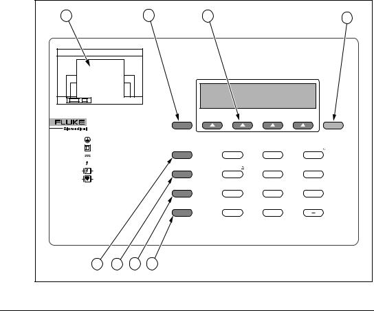
Figure 1-1: 601PRO Top Panel Illustration
Top Panel: Identifying 601PRO Components
Use the drawing of the 601PRO top panel, displayed above, to locate the following components.
APrinter
BPrevious Key
CSoft Keys 1-4
DEnter Key
EEsc/Stop Key
FView Present Settings Key
GPrint Header Key
HPrint Data Key
Optional 24-character printer for immediate hard copy of results. Returns user to the previous screen.
Make dynamic assignments based on current screen.
Advances to the next menu or saves/selects options.
Discontinues current test and returns operator to the MAIN MENU. Turns off the DUT outlet.
Advances to View Present Settings screen when at the MAIN MENU. Displays current settings and allows operator to edit test standard, class/type, and lead assignments (see page 3-7). Sends device information fields to enabled printer.
Sends displayed test data to printer.
1 - 6
I N T R O D U C T I O N A N D D E S C R I P T I O N
Keys Used to Enter Device Control Numbers
The keys described below (0 through –) can be used to enter test control numbers in the auto/step modes of operation. These keys are also referred to as test-shortcut keys and can be used to initiate manual tests.
0 |
Volts |
In single lead mode, displays mains voltage. |
|
|
|
|
In dual lead mode, displays voltage between |
|
|
|
RED and BLACK test leads. |
1 |
Current |
Measures the current consumption (in |
|
|
|
|
amperes) of the device under test. |
2 |
Insulation |
Tests insulation resistance (mains to case or |
|
|
|
|
applied parts to case). |
3 |
Protective Earth |
Measures the earth resistance using a 1A test |
|
|
|
Resistance |
current (unless 10A or 25A is selected). |
4 |
Earth Leakage |
Is measured between the DUT “Protective |
|
|
|
|
Earth” terminal and the “Protective Earth” |
|
|
|
terminal of the 601PRO. |
5 |
Enclosure Leakage |
In single-lead mode, measures the enclosure |
|
|
|
|
leakage (RED test lead to DUT protective |
|
|
|
earth on the 601PRO). |
|
6 |
Patient |
Measures the patient leakage current (applied |
|
|
Leakage |
part to earth. |
|
7 |
Mains on |
Applies 110% mains voltage to selected |
|
|||
|
|
Applied Part |
applied part and measures leakage to earth in |
|
|
Leakage |
both normal and reverse polarity. Does not |
|
|
|
apply to patient auxiliary selections. |
8 |
Patient Auxiliary |
Measures the leakage and biasing current |
|
|
|
Current |
between applied parts. |
9 |
IEC 1010 |
Selects the IEC 1010 Test Load. Measures |
|
|
|
Accessible |
accessible voltage through the RED jack to |
|
|
Voltage/Leakage |
601PRO earth. Allows access to the |
accessible leakage test.
/VDE Equivalent Selects the IEC 601 test load. Applies 110% Device Leakage of mains voltage between L1/L2 and earth.
–VDE Equivalent Selects the IEC 601 test load. Applies 110% Patient Leakage of mains voltage to the selected applied part
and measures the leakage.
1 - 7
6 0 1 P R O S E R I E S X L |
|
|
|
|
B |
|
|
A |
C |
E |
F |
|
|
||
|
|
D |
|
|
|
|
baw154f.eps |
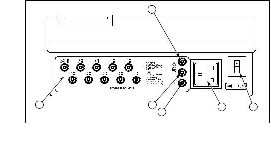
Figure 1-2: 601PRO Front Panel Illustration
Front Panel |
|
|
A |
Applied Part |
The jacks allow direct connection to |
|
Terminal |
banana jacks, or 4mm-to-alligator |
|
|
adapters provided. |
B |
Red Input |
Single test lead connection. |
|
Terminal |
|
C |
Black Input |
Used for dual lead testing in combination |
|
Terminal |
with red test lead. |
D |
Green Input |
Protective Earth of Device Under Test. |
|
Terminal |
|
E |
Power Outlet |
Allows standard power plug connection |
|
|
of the Device Under Test. 120V @ 15A |
|
|
or 240V @ 15A maximum. |
FOn-Off Switch / Power up the 601PRO, I=ON, 0=OFF; Circuit Breaker built-in ISA circuit breaker.
Note: To power up the 601PRO, place the index finger on the rocker switch and use a rolling motion to push from "OFF" to "ON." Do NOT forcefully push or snap the rocker switch. This may cause the unit to shut off.
1 - 8
|
|
I N T R O D U C T I O N A N D D E S C R I P T I O N |
A |
B |
C |
D |
|
E |
|
|
|
|
|
baw155f.eps |
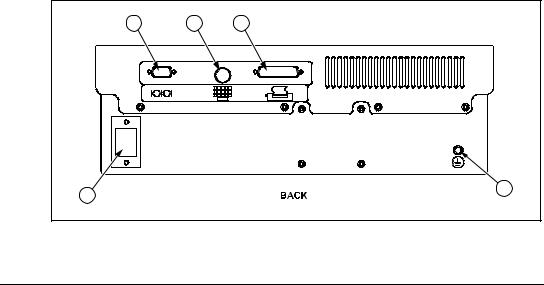
Figure 1-3: 601PRO Back Panel Illustration
Back Panel
A RS232 Connection Allows bi-directional computer control. Serial D-9 female connector.
B |
Keyboard Input |
Allows the use of an external keyboard |
|
|
for data input. DIN 5 socket. |
C |
Printer Connector |
Allows for an external parallel printer. |
|
|
D-25 female connector. |
D |
Power Cord |
120V/15A or 240V/15A power cord |
|
Connection |
connection. |
E |
Protective Earth |
Provides a direct connection to the |
|
Connection |
power cord ground. |
1 - 9
6 0 1 P R O S E R I E S X L
6.Statement of Compatibility
The 601PRO is compatible with and has the same base features as the previous 601PRO safety analyzer. It also has some new features that include the following:
•Because of new features in this version of the 601PRO, the Device Record Format has been changed. If old format device records are transmitted to
the 601PRO SeriesXL via RS232, they will be accepted. However, when receiving device records from the 601PRO, the new format will always be used. Refer to Chapter 6 for details.
•Custom standard names are fixed. Any old-style device record received via RS232 must be updated to reflect this change. Refer to Chapter 9 for more details.
•Supports all computer control commands from the previous 601PRO. Some of the commands no longer have meaning in the new 601PRO and have been given fixed responses. New commands have been added to support new features on the instrument. Refer to Chapter 10 for complete details.
•Due to new features, the RS232 result output format has changed. It is very similar to the old format but has extra fields for the new features. The transfer utility is no longer required or supported. Refer to Chapter 5 for complete details.
•Because the 601PRO now supports IEC 601, IEC 1010, and AAMI test loads, some changes in computer control commands have been made. All existing (previous) commands use the 601 test load. New commands have been created to support the new loads. Refer to Chapter 10 for details.
•Unlike previous versions of the 601PRO, the 601PRO SeriesXL uses a standard D9M-D9F serial cable.
1 - 1 0

Setting Up the 601PRO
Chapter
2
This chapter describes the factory default settings and how to change them, and provides instructions for one-time customization of the 601PROXL using the SYSTEM SETUP key and the Select Setup Function menu.
1.Using Factory Default Settings
2.Selecting the Test Standard
3.Selecting the Printer Output
4.Selecting the RS232 Baud Rate
5.Activating the Beeper
6.Setting the Time and Date
7.Configuring the Enclosure Leakage for the Auto Mode Sequence
8.Selecting Language Options
9.Selecting the DC Option
10.Selecting the Auto/Step Tests: Controlled Power Sequences or 601CE Conventional Test Sequences
11.Enabling Stop on Failure
12.Configuring for Device Records or Templates
1.Using Factory Default Settings
The factory default settings are shown below.
Description |
Factory Default Setting |
|
Test Standard |
IEC 601-1 (Class I, BF) |
|
Number of Applied Parts |
0 (To change, refer to Chapter 3) |
|
Printer Output |
Internal |
|
RS232 |
9600 Baud |
|
Beeper |
On |
|
Time Format |
24 hour |
|
Date Format |
MDY |
|
Enclosure Leakage (multiple readings |
Off |
|
during the Auto Mode sequence) |
|
|
Keyboard Language |
English |
|
Display/Print Language |
English |
|
DC Readings |
Off |
|
Auto/Step Sequences: Controlled Power |
On |
|
Sequence |
|
|
Stop on Failure |
Off |
|
DEV RECS / TEMPLATES |
DEVICE REC |
|
|
2-1 |
|
6 0 1 P R O S E R I E S X L
2.Selecting the Test Standard
The Select Test Standard option allows the operator to choose among IEC 601-1, VDE 701-1, VDE 751-1, HEI 95, IEC 1010, AAMI, AS/NZS 3551, or custom standards.
Refer to Chapter 8, Standards and Principles, for a detailed discussion of IEC 601-1, VDE 701-1, VDE 751-1, HEI 95, IEC 1010, AAMI, and AS/NZS 3551 standards and their selection.
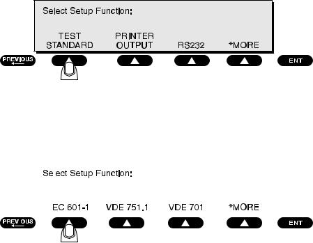
•At the 601PRO MAIN MENU, press SYSTEM SETUP to access the Select Setup Function menu. Press TEST STANDARD:
baw008f.eps
•At the Select Test Standard menu, select a test standard, or press *MORE for additional standards.
|
|
|
|
|
baw009f.eps |
|
|
|
|
|
|
|
|
|
|
|
|
|
|
|
|
|
|
|
|
|
|
|
|
|
|
|
|
|
|
|
|
|
|
|
|
Note: |
|
To enable/disable the test standards that appear at the Select Test |
|||
|
|
|
|
Standard menu, press UTILITIES at the MAIN MENU, then |
|
|
|
|
|
*MORE, then ENABLE STANDARDS. Press YES or NO at the |
|
|
|
|
|
Enable Test Standard menu. |
|
|
|
|
|
Once the selection is made, the 601PRO will automatically return |
|
|
|
|
|
to the MAIN MENU where the selected standard is displayed. |
|
Default Setting: IEC 601-1
2 - 2
S E T T I N G U P T H E 6 0 1 P R O
3.Selecting the Printer Output
Before testing, choose whether to use the optional internal printer, an external printer, or no printer.
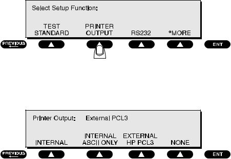
•From the 601PRO MAIN MENU, press SYSTEM SETUP to access the
Select Setup Function menu. Press PRINTER OUTPUT:
baw026f.eps
•At the Printer Output menu, use the SOFT KEYS to select a printer interface:
baw010f.eps
The EXTERNAL ASCII ONLY setting is for older (and some newer) printers that will interpret and print basic ASCII characters.
The EXTERNAL HP PCL3 printer setting is for any HP printer that supports PCL3 (Printer Control Language, Version 3). The control sequence feature configures the printer and then downloads ASCII characters to it.
Note: Follow the printer manufacturer’s instructions for handling page
ejects and printing using form-feed commands.
•Press previous or enter to save the settings and return to the MAIN MENU.
Default Setting: Internal
2 - 3
6 0 1 P R O S E R I E S X L
4.Selecting the RS232 Baud Rate
To select the baud rate for the RS232 serial port:
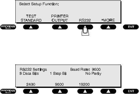
•From the 601PRO MAIN MENU, press SYSTEM SETUP to access the
Select Setup Function menu. Press RS232:
baw027f.eps
At the 601PRO RS232 Settings menu, press a SOFT KEY to select a baud rate:
baw011f.eps
Default Setting: 9600
•Press enter to save the setting and return to the Select Setup Function menu. Press previous to return to the MAIN MENU.
2 - 4
S E T T I N G U P T H E 6 0 1 P R O
5.Activating the Beeper
To activate/deactivate the beeper:
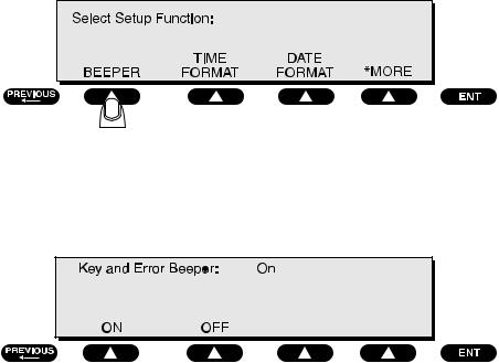
•From the 601PRO MAIN MENU, press SYSTEM SETUP to access the Select Setup Function menu. Press *MORE until the following menu is displayed, then press BEEPER:
baw012f.eps
•Press a SOFT KEY to select ON or OFF at the Key and Error Beeper menu:
baw025f.eps
Selecting OFF will silence the beep that sounds when a key is pressed or when an error occurs. Selecting OFF will not disable the beeper during lead calibration or when performing tests using the beeper as a warning.
Default Setting: ON
•Press enter to save the settings and return to the Select Setup Function menu. Press previous to return to the MAIN MENU.
2 - 5
6 0 1 P R O S E R I E S X L
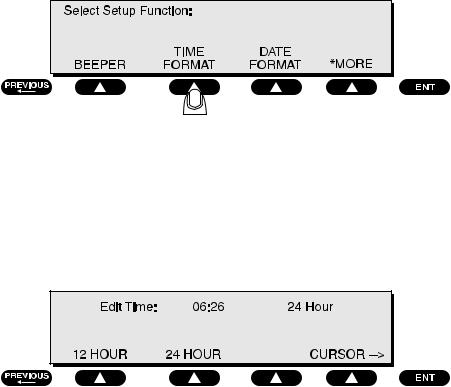
6.Setting the Time and Date
The time and date are used to record testing times and their associated dates. The clock can be set in either 12-hour or 24-hour format. The date format is either MM-DD-YY or DD-MM-YY.
To set the time format:
•From the 601PRO MAIN MENU, press SYSTEM SETUP to access the Select Setup Function menu. Press *MORE until the following menu is displayed, then press TIME FORMAT:
baw028f.eps
To set the time:
•At the following menu, press a SOFT KEY to select either the 12 HOUR or 24 HOUR format. Press the cursor SOFT KEY to change cursor position and enter the time of day using the test-shortcut keys.
baw013f.eps
Default Setting: 24 HOUR
•Press enter to save the settings and return to the Select Setup Function menu. Press previous to return to the MAIN MENU.
2 - 6
Loading...