


 Loading...
1662/1663/1664 FC
Electrical Installation Tester
Users Manual
October 2015, Rev. 1, 4/16
© 2015-2016 Fluke Corporation. All rights reserved. Specifications are subject to change without notice.
All product names are trademarks of their respective companies.
LIMITED WARRANTY AND LIMITATION OF LIABILITY
Each Fluke product is warranted to be free from defects in material and workmanship under normal use and service. The warranty period is three years and begins on the date of shipment. Parts, product repairs, and services are warranted for 90 days. This warranty extends only to the original buyer or end-user customer of a Fluke authorized reseller, and does not apply to fuses, disposable batteries, or to any product which, in Fluke's opinion, has been misused, altered, neglected, contaminated, or damaged by accident or abnormal conditions of operation or handling. Fluke warrants that software will operate substantially in accordance with its functional specifications for 90 days and that it has been properly recorded on non-defective media. Fluke does not warrant that software will be error free or operate without interruption.
Fluke authorized resellers shall extend this warranty on new and unused products to enduser customers only but have no authority to extend a greater or different warranty on behalf of Fluke. Warranty support is available only if product is purchased through a Fluke authorized sales outlet or Buyer has paid the applicable international price. Fluke reserves the right to invoice Buyer for importation costs of repair/replacement parts when product purchased in one country is submitted for repair in another country.
Fluke's warranty obligation is limited, at Fluke's option, to refund of the purchase price, free of charge repair, or replacement of a defective product which is returned to a Fluke authorized service center within the warranty period.
To obtain warranty service, contact your nearest Fluke authorized service center to obtain return authorization information, then send the product to that service center, with a description of the difficulty, postage and insurance prepaid (FOB Destination). Fluke assumes no risk for damage in transit. Following warranty repair, the product will be returned to Buyer, transportation prepaid (FOB Destination). If Fluke determines that failure was caused by neglect, misuse, contamination, alteration, accident, or abnormal condition of operation or handling, including overvoltage failures caused by use outside the product’s specified rating, or normal wear and tear of mechanical components, Fluke will provide an estimate of repair costs and obtain authorization before commencing the work. Following repair, the product will be returned to the Buyer transportation prepaid and the Buyer will be billed for the repair and return transportation charges (FOB Shipping Point).
THIS WARRANTY IS BUYER'S SOLE AND EXCLUSIVE REMEDY AND IS IN LIEU OF ALL OTHER WARRANTIES, EXPRESS OR IMPLIED, INCLUDING BUT NOT LIMITED TO ANY IMPLIED WARRANTY OF MERCHANTABILITY OR FITNESS FOR A PARTICULAR PURPOSE. FLUKE SHALL NOT BE LIABLE FOR ANY SPECIAL, INDIRECT, INCIDENTAL OR CONSEQUENTIAL DAMAGES OR LOSSES, INCLUDING LOSS OF DATA, ARISING FROM ANY CAUSE OR THEORY.
Since some countries or states do not allow limitation of the term of an implied warranty, or exclusion or limitation of incidental or consequential damages, the limitations and exclusions of this warranty may not apply to every buyer. If any provision of this Warranty is held invalid or unenforceable by a court or other decision-maker of competent jurisdiction, such holding will not affect the validity or enforceability of any other provision.
Fluke Corporation |
Fluke Europe B.V. |
P.O. Box 9090 |
P.O. Box 1186 |
Everett, WA 98206-9090 |
5602 BD Eindhoven |
U.S.A. |
The Netherlands |
11/99
Table of Contents
Title |
Page |
Introduction ................................................................................ |
1 |
How to Contact Fluke ................................................................. |
1 |
Safety ......................................................................................... |
2 |
Features and Accessories.......................................................... |
5 |
Operation ................................................................................... |
8 |
Safety Features ...................................................................... |
8 |
Touch Pad........................................................................... |
8 |
Live Circuit Detection .......................................................... |
8 |
Earth Resistance Measurement .......................................... |
8 |
Safety Pretest...................................................................... |
8 |
Mains Wiring Indicator......................................................... |
9 |
Quick Start.............................................................................. |
9 |
How to Use the Rotary Dial................................................. |
9 |
Push Buttons....................................................................... |
11 |
Display ................................................................................ |
13 |
Input Terminals ................................................................... |
17 |
Error Codes......................................................................... |
18 |
Power-On Options............................................................... |
20 |
How to Zero the Test Leads................................................ |
22 |
Safety Pretest for Insulation Resistance Measurements..... |
26 |
Measurements............................................................................ |
28 |
Volts and Frequency Measurements ...................................... |
28 |
Insulation Resistance Measurements ..................................... |
29 |
Continuity Measurement......................................................... |
32 |
Loop/Line Impedance Measurements..................................... |
34 |
Loop Impedance (Line to Protective Earth L-PE) ................ |
34 |
Loop Impedance (High-Current Trip Mode)......................... |
37 |
Loop Impedance in IT System Measurement...................... |
39 |
Line Impedance................................................................... |
39 |
RCD Tripping Time Measurements ........................................ |
42 |
Custom RCD Setting – Var mode ....................................... |
46 |
RCD Tripping Time in Auto mode ....................................... |
46 |
RCD Tripping Current Measurements .................................... |
48 |
RCD Tests in IT Systems ....................................................... |
52 |
Phase Rotation Tests ............................................................. |
54 |
Earth Resistance Measurements............................................ |
55 |
i

1662/1663/1664 FC |
|
Users Manual |
|
Applications ............................................................................... |
57 |
How to Test a Mains Socket and Ring Installation ................. |
57 |
Earth Resistance Test by Loop Method ................................. |
58 |
Zmax ...................................................................................... |
59 |
Auto Start ............................................................................... |
60 |
Loop Impedance Test with 10 mA RCD ................................. |
60 |
Auto Test Sequence (1664 FC).............................................. |
61 |
Memory Mode............................................................................ |
63 |
Store a Measurement............................................................. |
65 |
Recall a Measurement ........................................................... |
65 |
Clear Memory......................................................................... |
66 |
Memory Error Message.......................................................... |
66 |
Download Test Results.............................................................. |
67 |
Fluke Connect Wireless System ................................................ |
68 |
Maintenance .............................................................................. |
69 |
How to Test the Fuse ............................................................. |
70 |
How to Test the Battery.......................................................... |
70 |
Battery Replacement.............................................................. |
70 |
Specifications............................................................................. |
73 |
General Specifications ........................................................... |
73 |
Maximum Display Values ....................................................... |
75 |
Electrical Measurement Specifications................................... |
80 |
Operating Ranges and Uncertainties per EN 61557 .............. |
88 |
Operating Uncertainties per EN 61557................................... |
89 |
ii
List of Tables
Table |
Title |
Page |
1. |
Symbols ..................................................................................... |
4 |
2. |
Features ..................................................................................... |
5 |
3. |
Standard Accessories ................................................................ |
6 |
4. |
Country-Specific Mains Cords.................................................... |
7 |
5. |
Rotary Dial ................................................................................. |
10 |
6. |
Push Buttons.............................................................................. |
11 |
7. |
Display Features ........................................................................ |
13 |
8. |
Input Terminals........................................................................... |
17 |
9. |
Error Codes................................................................................ |
18 |
10. |
Power-On Options...................................................................... |
20 |
11. |
Volts Display/Dial and Terminal Settings.................................... |
28 |
12. |
Insulation Resistance Display/Dial and Terminal Settings.......... |
30 |
13. |
Continuity Zero Display/Dial and Terminal Settings ................... |
33 |
14. |
Loop/Line Impedance/Dial and Terminal Settings ...................... |
35 |
15. |
Line Impedance Test Display Dial and Terminal Settings .......... |
40 |
16. |
RCD Tripping Time Display/Dial and Terminal Settings ............. |
44 |
17. |
RCD Tripping Current/Dial and Terminal Settings...................... |
49 |
18. |
Earth Resistance Display/Dial and Terminal Settings ................ |
56 |
19. |
Auto Test Settings ...................................................................... |
62 |
20. |
Replacement Parts..................................................................... |
69 |
iii

1662/1663/1664 FC
Users Manual
iv
List of Figures
Figure |
Title |
Page |
1. |
Lead Swapping Modes............................................................... |
22 |
2. |
Zero Display ............................................................................... |
24 |
3. |
Country-Specific Zero Adapter Configurations ........................... |
25 |
4. |
Connection for Safety Pretest .................................................... |
26 |
5. |
Display for Safety Pretest........................................................... |
27 |
6. |
Loop Impedance Test in IT System............................................ |
39 |
7. |
3-Phase System Measurement .................................................. |
42 |
8. |
Connection for RCD Test on IT Electrical Systems .................... |
52 |
9. |
Single Test Lead Configuration .................................................. |
53 |
10. |
Phase Rotation Test Connection................................................ |
54 |
11. |
Phase Rotation Display .............................................................. |
54 |
12. |
Earth Resistance Test Connection............................................. |
55 |
13. |
3-Wire Connection for Earth Resistance Loop Test ................... |
58 |
14. |
2-Wire Connection for Earth Resistance Loop Test |
|
|
(High-Current Trip Mode) ........................................................... |
59 |
15. |
Memory Mode ............................................................................ |
64 |
16. |
IR Serial Cable Attachment ........................................................ |
67 |
17. |
Battery Replacement.................................................................. |
72 |
v

1662/1663/1664 FC
Users Manual
vi
Introduction
The Fluke 166X Series (the Tester or Product) are battery-powered electrical installation testers. This manual applies to all 1662, 1663, and 1664 FC models. All figures show the Model 1664 FC.
These Testers measure and test:
•Voltage and Frequency
•Insulation Resistance (EN61557-2)
•Continuity (EN61557-4)
•Loop/Line Resistance (EN61557-3)
•Residual Current Devices (RCD) Tripping Time (EN61557-6)
•RCD Tripping Current (EN61557-6)
•Phase Rotation (EN61557-7) 1663 and 1664 FC only
•Earth Resistance (EN61557-5)
How to Contact Fluke
To contact Fluke, call one of the following telephone numbers:
•Technical Support USA: 1-800-44-FLUKE (1-800-443-5853)
•Calibration/Repair USA: 1-888-99-FLUKE (1-888-993-5853)
•United Kingdom: +44 1603 256600
•Germany, Austria, Switzerland: +49 (0)69 / 2 22 22-0210
•Canada: 1-800-36-FLUKE (1-800-363-5853)
•Europe: +31 402-675-200
•Japan: +81-3-6714-3144
•Singapore: +65-6799-5566
•Anywhere in the world: +1-425-446-5500
Or, visit Fluke's website at www.fluke.com.
To register your product, visit http://register.fluke.com.
To view, print, or download the latest manual supplement, visit http://us.fluke.com/usen/support/manuals.
1

1662/1663/1664 FC
Users Manual
Safety
See Table 1 for a list of symbols used on the Product and in this manual.
A Warning identifies hazardous conditions and procedures that are dangerous to the user.
A Caution identifies conditions and procedures that can cause damage to the Product or the equipment under test.
XW Warnings
To prevent possible electrical shock, fire, or personal injury:
•Use the Product only as specified, or the protection supplied by the Product can be compromised.
•Carefully read all instructions.
•Read all safety information before you use the Product.
•Do not use the Product around explosive gas, vapor, or in damp or wet environments.
•Comply with local and national safety codes. Use personal protective equipment (approved rubber gloves, face protection, and flame-resistant clothes) to prevent shock and arc blast injury where hazardous live conductors are exposed.
•Do not use the Product in distribution systems with voltages >550 V.
•Use Product-approved measurement category (CAT), voltage, and amperage rated accessories (probes, test leads, and adapters) for all measurements.
•The battery door must be closed and locked before you operate the Product.
•Examine the case before you use the Product. Look for cracks or missing plastic. Carefully look at the insulation around the terminals.
•Do not use test leads if they are damaged. Examine the test leads for damaged insulation and measure a known voltage.
•Do not touch voltages >30 V ac rms, 42 V ac peak, or 60 V dc.
2
Electrical Installation Tester
Safety
•Use the correct terminals, function, and range for measurements.
•Do not apply more than the rated voltage between the terminals or between each terminal and earth ground.
•Do not exceed the Measurement Category (CAT) rating of the lowest rated individual component of a Product, probe, or accessory.
•Keep fingers behind the finger guards on the probes.
•Measure a known voltage first to make sure that the Product operates correctly.
•Replace the batteries when the low battery indicator shows to prevent incorrect measurements.
•Remove all probes, test leads, and accessories before the battery door is opened.
•Be sure that the battery polarity is correct to prevent battery leakage.
•Repair the Product before use if the battery leaks.
•Have an approved technician repair the Product.
•Use only specified replacement parts.
•Replace a blown fuse with exact replacement only for continued protection against arc flash.
•Do not operate the Product with covers removed or the case open. Hazardous voltage exposure is possible.
•Disable the Product if it is damaged.
•Do not use the Product if it is damaged.
•Remove the input signals before you clean the Product.
•Use only current probes, test leads, and adapters supplied with the Product.
•Remove test leads from the Product before the case is opened.
•Do not use in CAT III or CAT IV environments without the protective cap installed. The protective cap decreases the possibility of arc flash caused by short circuits.
3

1662/1663/1664 FC
Users Manual
|
Table 1. Symbols |
|
|
Symbol |
Description |
|
|
W |
WARNING. RISK OF DANGER. |
|
|
X |
WARNING. HAZARDOUS VOLTAGE. Risk of electric shock. |
|
|
|
Consult user documentation. |
|
|
|
Fuse |
T |
Double Insulated |
|
|
|
Earth |
|
|
|
WARNING. Do not apply >550 Volts. |
|
|
,/ - |
Battery Status |
|
|
|
Measurement Category III is applicable to test and measuring circuits |
connected to the distribution part of the building’s low-voltage MAINS |
|
|
installation. |
|
|
|
Measurement Category IV is applicable to test and measuring circuits |
connected at the source of the building’s low-voltage MAINS installation. |
|
|
|
P |
Conforms to European Union directives. |
|
|
) |
Certified by CSA Group to North American safety standards. |
|
|
|
Conforms to relevant Australian EMC standards. |
|
|
|
Certified by TÜV SÜD Product Service. |
|
|
|
This product complies with the WEEE Directive marking requirements. |
|
The affixed label indicates that you must not discard this |
~ |
electrical/electronic product in domestic household waste. Product |
Category: With reference to the equipment types in the WEEE Directive |
|
Annex I, this product is classed as category 9 "Monitoring and Control |
|
|
Instrumentation" product. Do not dispose of this product as unsorted |
|
municipal waste. |
|
|
4

Electrical Installation Tester
Features and Accessories
Features and Accessories
Table 2 is a list of features by model number.
Table 2. Features
|
|
Measurement Function |
1662 |
1663 |
1664 FC |
Voltage & Frequency |
• |
• |
• |
||
Wiring polarity checker |
• |
• |
• |
||
Insulation Resistance |
• |
• |
• |
||
Insulation safety pretest |
|
|
• |
||
Continuity & Resistance with auto polarity swap |
• |
• |
• |
||
Continuity & Resistance with 10 mA |
• |
• |
• |
||
Continuity & Resistance, choose input terminals |
|
• |
• |
||
with . |
|
|
|
|
|
Zmax memory |
|
|
|
• |
• |
Loop & Line Resistance |
• |
• |
• |
||
Loop & Line Resistance–mHresolution |
|
|
• |
||
Prospective Earth Fault Current (PEFC/IK) Prospective |
• |
• |
• |
||
Short-Circuit current (PSC/IK) |
|
|
|
||
RCD tripping time |
• |
• |
• |
||
RCD tripping level (ramp test) |
• |
• |
• |
||
RCD variable current |
• |
• |
• |
||
Automatic RCD test sequence |
• |
• |
• |
||
Test pulse current sensitive RCDs (Type A) |
• |
• |
• |
||
Test smooth dc sensitive RCDs (Type B) |
|
• |
• |
||
Earth Resistance |
|
• |
• |
||
Phase Rotation Indicator |
• |
• |
• |
||
Auto test sequence |
|
|
• |
||
|
|
Other Features |
|
|
|
Self-test |
|
|
• |
• |
• |
Illuminated Display |
• |
• |
• |
||
Fluke Connect |
™ |
Wireless System |
|
|
• |
|
|
|
|
||
|
|
Memory, Interface |
|
|
|
Memory and Computer Interface |
• |
• |
• |
||
Fluke DMS Software (optional accessory) |
• |
• |
• |
||
Fluke FVF Software (optional accessory) |
• |
• |
• |
||
Fluke Connect |
™ |
smartphone app |
|
|
• |
|
|
|
|
||
|
|
Included Accessories |
|
|
|
Hard case |
|
|
• |
• |
• |
Remote control probe |
• |
• |
• |
||
Zero Adapter |
|
|
• |
• |
• |
5

1662/1663/1664 FC
Users Manual
The Product is delivered with the items listed in Table 3. If the Product is damaged or an item is missing, contact the place of purchase immediately.
Table 3. Standard Accessories
Description
TP165X Test Probe with Remote Test Button
Country-Specific Mains Test Cord
TL-L1, Test Lead, Red
TL-L2, Test Lead Green
TL-L3, Test Lead Blue
Probe, Test, Banana Jack, 4 mm Tip, Red
Probe, Test, Banana Jack, 4 mm Tip, Green
Probe, Test, Banana Jack, 4 mm Tip, Blue
102-406-003, Probe cap,GS-38 Red
102-406-002, Probe cap,GS-38 Green
102-406-004, Probe cap,GS-38 Blue
1662 EU |
1663/1664 FC EU |
1662 UK |
1663/1664 FC UK |
• |
• |
• |
• |
• |
• |
• |
• |
••
••
••
••
••
••
••
••
••
Part Number
2107742
See Table 4
2044945
2044950
2044961
2099044
2065297
2068904
1942029
2065304
2068919
6

Electrical Installation Tester
Operation
Table 3. Standard Accessories (cont.)
Description
1662 EU |
1663/1664 FC EU |
1662 UK |
1663/1664 FC UK |
|
|
|
|
Part Number
AC285-5001,175-276-013 AC285 Large |
• |
• |
|
|
2041727 |
alligator clip, Red |
|
|
|
|
|
|
|
|
|
|
|
|
|
|
|
|
|
AC285-5001-02,175-276-012 AC285 |
• |
• |
|
|
2068133 |
Large alligator clip, Green |
|
|
|
|
|
|
|
|
|
|
|
|
|
|
|
|
|
AC285-5001-03,175-276-0114 AC285 |
• |
• |
|
|
2068265 |
Large alligator clip, Blue |
|
|
|
|
|
|
|
|
|
|
|
Fused Probe Set, Red/Blue/Green with |
|
|
• |
• |
3989868 |
Lantern Spring, Cap, and Tip Cover |
|
|
|
|
|
CD ROM, Users Manual |
• |
• |
• |
• |
4477435 |
|
|
|
|
|
|
Quick Reference Guide |
• |
• |
• |
• |
4477545 |
|
|
|
|
|
|
Tool Box (Hard Case with foam insert) |
• |
• |
• |
• |
4688513 |
|
|
|
|
|
|
Carrying Strap, Padded |
• |
• |
• |
• |
4502043 |
|
|
|
|
|
|
Fluke Zero Adapter |
• |
• |
• |
• |
3301338 |
|
|
|
|
|
|
Table 4 is a list of the country-specific mains cords.
Table 4. Country-Specific Mains Cords
Mains Cord |
Plug Type |
Part Number |
|
|
|
British |
BS1363 |
4601070 |
Schuko |
CEE 7/7 |
4601081 |
Denmark |
AFSNIT 107-2-DI |
4601129 |
Australia/New Zealand |
AS 3112 |
4601118 |
Switzerland |
SEV 1011 |
4601107 |
Italy |
CEI 23-16/VII |
4601096 |
USA |
NEMA 5-15 |
4601134 |
7

1662/1663/1664 FC
Users Manual
Operation
The Product is easy to use. The rotary dial clearly indicates the selected function. Push buttons help you to quickly modify the test settings. The large display with backlight shows the test results in clear symbols on a one-level menu.
Safety Features
Safety and performance are two of the most critical requirements for any electrical system. Good quality insulation, a properly working grounding system, and active protection assure the safety of people, electrical systems and buildings. These factors protect them against electrocution, fire, and other equipment damage.
Touch Pad
The button is surrounded by a touch pad (see Table 6). The touch pad
measures the potential between the operator and the PE terminal on the Tester. If the touch pad potential exceeds 100 V, the W symbol above the touch pad is lit, the PE annunciator in the display is lit, and the beeper sounds.
Live Circuit Detection
For continuity and insulation resistance measurements, the Product inhibits the test if the terminal voltage detected is >30 volts ac/dc before the test starts. The beeper sounds continuously if this voltage is present.
Earth Resistance Measurement
The Product inhibits the test if >10 volts is detected between the test rods. More information about Earth Resistance measurements is on page 55.
Safety Pretest
The 1664 FC model includes a Safety Pretest feature that detects any appliances connected to the circuit under test. The Safety Pretest gives you a warning before you start a test and prevents damage to appliances from the test voltage. More information about Safety Pretest is on page 26.
8

Electrical Installation Tester
Operation
Mains Wiring Indicator
Icons ( , b, c) indicate if L-PE or L-N terminals are reversed. Instrument operation is inhibited and an error code is generated if the input voltage is not between 100 V and 500 V. The UK Loop and RCD tests are inhibited if the L-PE or the L-N terminals are reversed.
When a high voltage is measured between two wires, shows on the display. See How to Test a Mains Socket and Ring Installation for more information.
Quick Start
This section is information that introduces you to the controls and inputs of the Tester. You will also find information about functions that apply globally as you use the Tester.
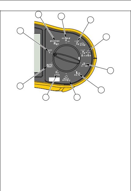
How to Use the Rotary Dial
Use the rotary dial (see Table 5) to select the test type.
9
1662/1663/1664 FC
Users Manual
Table 5. Rotary Dial
2 |
3 |
|
4 |
1 |
10 |
9 |
8 |
5 |
6 |
7 |
hwl013f.eps
Item |
Symbol |
Measurement Function |
|
V |
Volts |
|
|
|
|
|
Insulation resistance |
|
|
|
|
|
Continuity |
|
|
|
|
|
Loop/line impedance — No trip mode |
|
|
|
|
|
Loop/line impedance — High-current trip mode |
|
|
|
|
|
RCD tripping time |
|
|
|
|
j |
RCD tripping level |
|
|
|
|
|
Phase rotation |
|
|
|
|
|
Earth resistance (1663 and 1664 FC only) |
|
|
|
|
* |
Auto Test (1664 FC only) |
|
|
|
10
Electrical Installation Tester
Operation
Push Buttons
Use the push buttons (Table 6) to control operation of the Tester, select test results to view, and scroll through selected test results.
Table 6. Push Buttons
1
9
8 |
7 |
6 |
2
3
5 |
4 |
hwl012f.eps
Item |
Push |
Description |
|
Button |
|||
|
|
||
|
|
1664 FC only – Turn on the radio for Fluke Connect. Press |
|
for >1 s to turn off the radio. |
|||
|
|
Go to/exit Memory mode.
|
|
Adjust function settings. See specific test instructions for |
|
|
more information. |
11
1662/1663/1664 FC
Users Manual
|
|
Table 6. Push Buttons (cont.) |
|
|
|
|
|
No. |
Push |
Description |
|
Button |
|||
|
|
||
|
|
|
|
|
|
Use the up/down button to select features on the display. |
|
See specific test instructions for more information. |
|||
|
|||
|
|
|
|
|
|
Turn on and turn off the Tester. The Tester turns off |
|
automatically when inactive for >10 minutes. |
|||
|
|
||
|
|
|
|
|
A |
Turn on and turn off the backlight. |
|
|
|
|
|
|
|
Starts the selected test. |
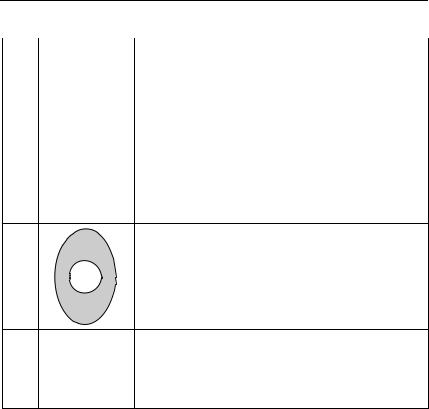
Touch Pad. The button is surrounded by a touch pad.
|
Always contact the touch pad before . |
The touch pad measures the potential between the operator and the Tester’s PE terminal, except in phase rotation.
Voltage warning. If the touch pad potential is >100 V, the Wsymbol above the touch pad illuminates, the PE
W annunciator in the display is lit, and the beeper sounds. RCD and Loop tests will be inhibited. Not valid when measuring phase rotation.
12

Electrical Installation Tester
Operation
Display
Table 7 is a list of the display features.
Table 7. Display Features
|
26 |
25 |
24 |
23 |
|
22 |
21 |
|
20 |
|
|
27 |
|
|
|
|
|
||
|
|
|
|
|
|
|
|
||
|
|
|
|
|
|
|
|
|
|
|
|
|
|
|
|
|
|
|
19 |
1 |
|
|
|
|
|
|
|
|
18 |
|
|
|
|
|
|
|
|
|
|
2 |
|
|
|
|
|
|
|
|
|
|
|
|
|
|
|
|
|
|
17 |
3 |
|
|
|
|
|
|
|
|
16 |
|
|
|
|
|
|
|
|
|
|
|
|
|
|
|
|
|
|
|
15 |
|
|
|
|
|
|
|
|
|
14 |
4 |
|
|
|
|
|
|
|
|
|
5 |
|
6 |
7 |
|
|
8 |
|
|
|
|
|
9 |
11 |
10 |
12 |
13 |
|||
|
|
|
|
|
|||||
|
|
|
|
|
|
|
|
|
|
|
|
|
|
|
|
|
|
|
hwl020.eps |
Item |
Annunciator |
|
|
|
|
Definition |
|
||
|
settings |
Function varies. See specific test instructions for |
|
more information. |
|||
|
|
||
|
settings |
Function varies. See specific test instructions for |
|
more information. |
|||
|
|
||
|
|
|
|
|
settings |
Function varies. See specific test instructions for |
|
more information. |
|||
|
|
||
|
|
|
|
D |
settings |
Function varies. See specific test instructions for |
|
more information. |
|||
|
|
Illuminates only when the touch pad is touched to E PE indicate that the PE input carries a high voltage
(>100 V).
F |
|
Turns on when you press the Test button. Turns off |
|
when the test is complete. |
|||
|
|
13

1662/1663/1664 FC
Users Manual
Table 7. Display Features (cont.)
Item |
Annunciator |
Definition |
|
|
|
|
|
|
+ |
Safety Pretest has detected a connected |
|
G |
appliance and stopped the test. See Insulation |
||
|
|
Resistance Measurements for more information. |
|
|
|
|
|
|
W |
Risk of danger. Appears when an error occurs. |
|
H |
Test is disabled. See Table 9 for a list and |
||
|
|
explanation of possible error codes. |
|
|
|
|
|
|
Name of the secondary measurement function: |
||
|
ZI |
Line impedance (line to neutral). |
|
|
|||
|
UN |
Test voltage for insulation test. |
|
|
PSC |
Prospective Short Circuit. Calculated from |
|
|
|
measured voltage and impedance when reading |
|
|
|
line to neutral. |
|
I |
UF |
Fault voltage. Measures neutral to earth. |
|
PEFC |
|
||
|
Prospective Earth Fault Current. Calculated from |
||
|
|
voltage and loop impedance that is measured line |
|
|
|
to protective earth. |
|
|
IK |
In combination with the PSC or PEFC symbol, |
|
|
|
indicates a short circuit current. |
|
|
Zmax |
Recorded maximum value of chosen loop test. |
|
|
RE |
Earth resistance |
|
|
K |
Appears when the Tester is overheated. The Loop |
|
|
test and RCD functions are inhibited when the |
||
|
|
Tester is overheated. |
|
|
|
|
|
K |
|
More results are available. Use to scroll through |
|
the results. |
|||
|
|
||
|
|
|
|
14
|
|
|
Electrical Installation Tester |
|
|
|
|
Operation |
|
|
|
Table 7. Display Features (cont.) |
|
|
|
|
|
|
|
|
Item |
Annunciator |
Definition |
|
|
|
|
|
|
|
|
|
Secondary display. A test can return more than |
|
|
L |
|
one result or return a computed value based on |
|
|
|
the test result. See specific test instructions for |
|
|
|
|
|
|
|
|
|
|
more information. |
|
|
|
|
|
|
|
|
V |
|
|
|
M |
H± |
Measurement units for Secondary display. |
|
|
kA |
|
||
|
|
|
|
|
|
|
Hz |
|
|
|
N |
h |
Memory locations. See Memory Mode for detailed |
|
|
information on how to use the memory locations. |
|
||
|
|
|
|
|
|
|
|
|
|
|
|
, |
Battery status. See How to Test the Battery and |
|
|
O |
Battery Replacement sections for additional |
|
|
|
|
|
information on batteries and power management. |
|
Shows when you press .
P |
|
Shows when you press and look at stored |
|
|
|||
|
data. |
||
|
|
|
|
|
|
|
|
Q |
Memory locations. See Memory Mode for detailed |
||
|
|
|
information on how to use the memory locations. |
|
|
ms |
Measurement units for primary display. |
|
|
mV |
|
R |
|
mA |
|
|
MH± |
|
|
|
|
mH |
|
|
|
|
Primary display. |
S |
|
|
|
|
|
|
|
|
|
|
|
|
|
|
Indicates the preset fault voltage limit. The default |
T |
|
|
setting is 50 V. Some locations require the fault |
|
|
voltage be set to 25 V, as specified by local |
|
|
|
|
|
|
|
|
electrical codes. |
15

1662/1663/1664 FC
Users Manual
Table 7. Display Features (cont.)
Item |
Annunciator |
|
Definition |
||||
|
|
|
|
|
|
|
|
U |
|
|
|
|
|
Indicates the selected rotary dial setting. The |
|
|
|
|
|
|
measurement value in the primary display also |
||
|
|
|
|
|
|
corresponds to the dial setting. |
|
|
|
|
|
|
|
Indicates that the measured trip current (trip |
|
|
|
RCD |
current test) or the measured trip time (trip time |
||||
V |
|
test) meets the appropriate RCD standard. For |
|||||
|
|
|
|
|
|
more information, see the RCD Tripping Time |
|
|
|
|
|
|
|
table in the Specifications section of this manual. |
|
|
|
|
|
|
|
|
|
|
|
|
|
|
|
Terminal indicator symbol (e). A terminal indicator |
|
|
|
|
|
|
|
symbol with a dot (d) in the center indicates the |
|
|
|
|
e/d |
terminal is required for the selected function. The |
|||
|
|
|
terminals are: |
||||
|
|
|
|
|
|
• |
L (Line) |
|
|
|
|
|
|
• |
PE (Protective Earth) |
W |
|
|
|
|
|
• |
N (Neutral) |
|
|
Arrows above or below the terminal indicator |
|||||
|
symbol indicate reversed polarity. Check the |
||||||
|
|
|
|
|
|
connection or check the wiring to correct. |
|
An “X” through the terminal indicator symbol
indicates that the wire, test lead, and/or installation wire are broken.
X |
|
High voltage present. |
|
|
|
Y |
C |
Data exchange with PC in process. |
|
|
|
|
|
Appears when the leads are successfully zeroed. |
|
|
After the zeroing procedure, the icon illuminates to |
Z |
indicate that the zero value is stored for the |
|
|
|
selected input terminals. Only used for continuity or |
|
|
loop tests. |
|
|
|
|
|
Radio is turned on. If blinks steadily, 1664 FC |
|
|
is searching to connect. If it blinks at 5 s intervals, |
a |
1664 FC is connected to the Fluke Connect app. |
|
|
|
For more information about Fluke Connect, see |
|
|
page 68. |
16
Electrical Installation Tester
Operation
Input Terminals
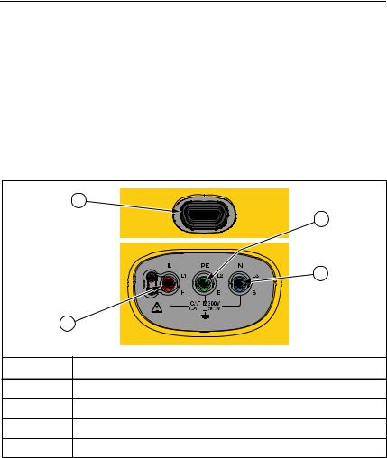
Table 8 shows the input terminals.
XW Warning
To prevent possible electrical shock, fire, or personal injury, do not use test leads in CAT III or CAT IV environments without the protective cap installed. The protective cap decreases the exposed probe metal to <4 mm. This decreases the possibility of arc flash from short circuits.
Table 8. Input Terminals
1 |
3 |
4 |
2 |
hwl021f.eps
Item |
Description |
IR Port
L/L1/H (Line)
PE/L2/E (Protective Earth)
D |
N/L3/S (Neutral) |
The IR (infrared) port allows you to connect the Tester to a computer and download the test data with a Fluke PC software product. With the software, you can collect, organize, and display the test data in a format that meets your needs. See Download Test Results for additional information on using the IR port.
17
1662/1663/1664 FC
Users Manual
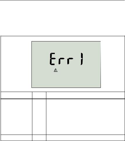
Error Codes
Various error conditions are detected by the Tester and are indicated with W, Err, and an error code on the primary display. See Table 9. These error conditions disable or stop the test.
Table 9. Error Codes
apx032f.eps
Error Condition Code |
Solution |
Return the Tester to a Fluke Service Center.
Secondary display shows additional code:
|
|
1: |
Unable to communicate with Analog board |
|
|
2: |
Analog board operating variables errors |
Self-Test Fails |
1 |
4: |
Fuse 1 error |
|
|
8: |
Fuse 3 error (display shows FUSE) |
16: Analog board ID does not match expected value 32: Digital flash CRC fault
64: Analog flash CRC fault
Over-Temp |
2 |
Wait while the Tester cools down. |
18
|
|
|
Electrical Installation Tester |
|
|
|
Operation |
|
|
Table 9. Error Codes (cont.) |
|
|
|
|
|
|
Error Condition |
Code |
Solution |
|
|
|
|
|
Fault Voltage |
4 |
Check the voltage between N and PE. RCD, socket |
|
test, UL is exceeded. Loop test no trip >10 V. |
||
|
|
|
|
|
Excessive Noise |
5 |
Turn off all appliances (Loop, RCD measurements) or |
|
move the earth stakes (earth measurement). |
||
|
|
|
|
|
|
|
|
|
Excessive Probe |
|
Put the stakes deeper into the soil. Tamp down the |
|
6 |
soil directly around the stakes. Pour water around the |
|
|
Resistance |
||
|
|
stakes but not at the earth ground under test. |
|
|
|
|
|
|
|
|
|
|
|
|
The data memory is inconsistent. Download and save |
|
Data Memory |
9 |
all data to a PC and clear all memory in the Tester. If |
|
the error persists, return the Tester to a Fluke Service |
||
|
|
|
|
|
|
|
Center. |
|
|
|
|
19

1662/1663/1664 FC
Users Manual
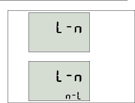
Power-On Options
To select a power-on option, press and the function push button simultaneously and then release . See Table 10 for a description of the options. Power-on options are retained when the Tester is turned off.
|
|
Table 10. Power-On Options |
|
|
|
|
|
Push |
Power-On |
Description |
|
Button |
Option |
||
|
|||
|
Firmware |
Turn on the Tester and press for >3 s. The firmware |
|
|
Version |
version shows when you release . |
|
|
IT mode |
In IT mode, a loop test or an RCD test is allowed even if |
|
the voltage N-PE is higher than 25 V / 50 V. The default |
|||
|
toggle |
setting is IT OFF. |
|
|
|
||
|
|
|
|
|
|
Configure the Tester to operate in L-n mode or L-n n-L |
|
|
|
mode, see Figure 1. |
|
|
|
• In L-n mode, the L and N phase conductors must |
|
|
|
NEVER be reversed. This is a requirement in the UK |
|
|
|
and other regions. The bicon appears on the |
|
|
|
display to indicate that the system L and N conductors |
|
|
|
are swapped and the test is inhibited. Investigate and |
|
|
Line and |
rectify the cause of this system fault before you |
|
|
continue. L-n mode also changes the RCD x1/2 trip |
||
|
Neutral |
time duration to 2000 ms. for UK requirement. |
|
Swap mode |
• In L-n n-L mode, the unit allows the L and N phase |
||
|
toggle |
conductors to be swapped and tests will continue. |
|
|
|
Note |
|
|
|
In locations where polarized plugs and outlets are |
|
|
|
used, a swapped lead icon (b) may indicate |
|
|
|
that the outlet was wired incorrectly. Correct this |
|
|
|
problem before you continue with any tests. |
|
|
|
The default setting in the UK is L-n. Elsewhere, the default |
|
|
|
setting is L-n n-L. |
|
|
|
|
20
|
|
|
Electrical Installation Tester |
|
|
|
Operation |
|
|
Table 10. Power-On Options (cont.) |
|
|
|
|
|
|
Push |
Power-On |
Description |
|
Button |
Option |
|
|
|
||
|
|
Fault voltage |
Toggles the fault voltage between 25 V and 50 V. The |
|
|
limit |
default setting is 50 V. |
|
|
Serial |
Primary display shows the initial four digits and the |
|
|
Number |
secondary display shows the next three digits. |
|
A |
Continuity |
Turn on and turn off the beeper. The default setting is |
|
|
beeper |
bEEP on. |
|
|
Auto Start |
Automatic test start toggle. Simultaneously press and |
|
|
|
the UP cursor. When turned on, the unit starts an RCD or |
|
|
|
loop test if mains voltage is detected. You do not need to |
|
|
|
press . The default setting is AUSt oFF. |
|
|
0 Hz/128 Hz |
No Trip Loop test measurement frequency toggle. |
|
|
Simultaneously press and the DOWN cursor. Use |
|
|
|
0 Hz if the RCD under test has high impedance with the |
|
|
|
|
higher frequency. The default setting is 128 Hz. |
|
|
|
Note |
|
|
|
0 Hz is not available in the Auto Test |
|
|
|
Sequence. |
|
|
|
|
21
1662/1663/1664 FC
Users Manual
UK - Mode
Selected
Automatic Lead
Swapping
Mode Selected
apx026f.eps
Figure 1. Lead Swapping Modes
How to Zero the Test Leads
XW Warning
To prevent possible electrical shock, fire, or personal injury, do not use in CAT III or CAT IV environments without the protective cap installed. The protective cap decreases the exposed probe metal to <4 mm. This decreases the possibility of arc flash from short circuits.
Test leads have a small amount of inherent resistance that can affect a measurement. Before you do continuity or loop impedance tests, use the zero adapter to compensate for, or zero, the test leads or the mains cord. See Figure 2 and Figure 3 for more information about the zero adapter.
22
Loading...