


 Loading...
525B
Temperature/Pressure Calibrator
Users Manual
July 2012
© 2012 Fluke Corporation, All rights reserved.
All product names are trademarks of their respective companies.
LIMITED WARRANTY AND LIMITATION OF LIABILITY
Each Fluke product is warranted to be free from defects in material and workmanship under normal use and service. The warranty period is one year and begins on the date of shipment. Parts, product repairs, and services are warranted for 90 days. This warranty extends only to the original buyer or end-user customer of a Fluke authorized reseller, and does not apply to fuses, disposable batteries, or to any product which, in Fluke's opinion, has been misused, altered, neglected, contaminated, or damaged by accident or abnormal conditions of operation or handling. Fluke warrants that software will operate substantially in accordance with its functional specifications for 90 days and that it has been properly recorded on non-defective media. Fluke does not warrant that software will be error free or operate without interruption.
Fluke authorized resellers shall extend this warranty on new and unused products to end-user customers only but have no authority to extend a greater or different warranty on behalf of Fluke. Warranty support is available only if product is purchased through a Fluke authorized sales outlet or Buyer has paid the applicable international price. Fluke reserves the right to invoice Buyer for importation costs of repair/replacement parts when product purchased in one country is submitted for repair in another country.
Fluke's warranty obligation is limited, at Fluke's option, to refund of the purchase price, free of charge repair, or replacement of a defective product which is returned to a Fluke authorized service center within the warranty period.
To obtain warranty service, contact your nearest Fluke authorized service center to obtain return authorization information, then send the product to that service center, with a description of the difficulty, postage and insurance prepaid (FOB Destination). Fluke assumes no risk for damage in transit. Following warranty repair, the product will be returned to Buyer, transportation prepaid (FOB Destination). If Fluke determines that failure was caused by neglect, misuse, contamination, alteration, accident, or abnormal condition of operation or handling, including overvoltage failures caused by use outside the product’s specified rating, or normal wear and tear of mechanical components, Fluke will provide an estimate of repair costs and obtain authorization before commencing the work. Following repair, the product will be returned to the Buyer transportation prepaid and the Buyer will be billed for the repair and return transportation charges (FOB Shipping Point).
THIS WARRANTY IS BUYER'S SOLE AND EXCLUSIVE REMEDY AND IS IN LIEU OF ALL OTHER WARRANTIES, EXPRESS OR IMPLIED, INCLUDING BUT NOT LIMITED TO ANY IMPLIED WARRANTY OF MERCHANTABILITY OR FITNESS FOR A PARTICULAR PURPOSE. FLUKE SHALL NOT BE LIABLE FOR ANY SPECIAL, INDIRECT, INCIDENTAL, OR CONSEQUENTIAL DAMAGES OR LOSSES, INCLUDING LOSS OF DATA, ARISING FROM ANY CAUSE OR THEORY.
Since some countries or states do not allow limitation of the term of an implied warranty, or exclusion or limitation of incidental or consequential damages, the limitations and exclusions of this warranty may not apply to every buyer. If any provision of this Warranty is held invalid or unenforceable by a court or other decision-maker of competent jurisdiction, such holding will not affect the validity or enforceability of any other provision.
Fluke Corporation |
Fluke Europe B.V. |
P.O. Box 9090 |
P.O. Box 1186 |
Everett, WA 98206-9090 |
5602 BD Eindhoven |
U.S.A. |
The Netherlands |
11/99
To register your product online, visit register.fluke.com
Table of Contents
Chapter |
Title |
Page |
|
1 |
Getting Started................................................................................... |
|
1-1 |
|
Introduction...................................................................................................... |
|
1-1 |
|
Contacting Fluke.............................................................................................. |
|
1-1 |
|
Standard Equipment......................................................................................... |
|
1-2 |
|
Options and Accessories.................................................................................. |
|
1-2 |
|
Safety Information ........................................................................................... |
|
1-2 |
|
Getting Acquainted with the Calibrator........................................................... |
1-5 |
|
|
Input and Output Terminals ...................................................................... |
|
1-5 |
|
Using the Keys .......................................................................................... |
|
1-6 |
|
Display Error Messages ............................................................................ |
|
1-10 |
|
Rear Panel View........................................................................................ |
|
1-11 |
2 |
Using Output Mode ........................................................................... |
|
2-1 |
|
Using Output Mode ......................................................................................... |
|
2-1 |
|
Simulating Thermocouple Temperature.................................................... |
2-2 |
|
|
Simulating Temperature Using Resistance Temperature |
|
|
|
Detectors (RTDs) ...................................................................................... |
|
2-3 |
|
Simulating Custom RTD Coefficients ...................................................... |
2-4 |
|
|
Default RTD Coefficients ......................................................................... |
|
2-5 |
|
Entering Custom Standard Platinum Resistance Thermometer (SPRT) |
|
|
|
Coefficients ............................................................................................... |
|
2-6 |
|
Output DC Voltage.................................................................................... |
|
2-7 |
|
Output Resistance...................................................................................... |
|
2-8 |
|
Output Current ................................................................................................. |
|
2-9 |
3 |
Using Input Mode .............................................................................. |
|
3-1 |
|
Using Input Mode ............................................................................................ |
|
3-1 |
|
Measuring Resistance................................................................................ |
|
3-1 |
|
Measuring Temperature Using Thermocouples ........................................ |
3-2 |
|
i

525B
Users Manual
|
Thermocouple Zero Calibration ........................................................... |
3-4 |
|
Measuring Temperature Using Resistance Temperature |
|
|
Detectors (RTDs)...................................................................................... |
3-5 |
|
Entering and Using Custom RTDs ........................................................... |
3-7 |
|
Default RTD Coefficients......................................................................... |
3-8 |
|
Entering Custom SPRT Coefficients ........................................................ |
3-9 |
|
Measuring Pressure................................................................................... |
3-10 |
4 |
Remote Operation ............................................................................. |
4-1 |
|
Introduction ..................................................................................................... |
4-1 |
|
Setting up the RS-232 Port for Remote Control.............................................. |
4-2 |
|
RS-232 Port Setup Procedure ................................................................... |
4-2 |
|
Testing the RS-232 Port ....................................................................... |
4-2 |
|
RS-232 Interface Overview............................................................................. |
4-5 |
|
Setting up the IEEE-488 Port for Remote Control.......................................... |
4-5 |
|
IEEE-488 Port Setup Procedure ............................................................... |
4-7 |
|
Testing the IEEE-488 Port........................................................................ |
4-7 |
|
Changing Between Remote and Local Operation ........................................... |
4-8 |
|
Local State ................................................................................................ |
4-8 |
|
Local with Lockout State.......................................................................... |
4-8 |
|
Remote State............................................................................................. |
4-8 |
|
Remote with Lockout State....................................................................... |
4-9 |
|
IEEE-488 Interface Overview ......................................................................... |
4-10 |
|
Using Commands ............................................................................................ |
4-13 |
|
Types of Commands ................................................................................. |
4-13 |
|
Device-Dependent Commands............................................................. |
4-13 |
|
Common Commands............................................................................ |
4-13 |
|
Query Commands................................................................................. |
4-14 |
|
Interface Messages (IEEE-488)............................................................ |
4-14 |
|
Compound Commands ......................................................................... |
4-16 |
|
Overlapped Commands ........................................................................ |
4-16 |
|
Sequential Commands.......................................................................... |
4-17 |
|
Commands for RS-232 Only ................................................................ |
4-17 |
|
Commands for IEEE-488 Only ............................................................ |
4-17 |
|
Command Syntax...................................................................................... |
4-18 |
|
Parameter Syntax Rules........................................................................ |
4-18 |
|
Extra Space or Tab Characters ............................................................. |
4-19 |
|
Terminators .......................................................................................... |
4-19 |
|
Incoming Character Processing............................................................ |
4-20 |
|
Response Message Syntax.................................................................... |
4-20 |
|
Checking 525B Status ..................................................................................... |
4-21 |
|
Serial Poll Status Byte (STB) ................................................................... |
4-23 |
|
Service Request (SRQ) Line ................................................................ |
4-23 |
|
Service Request Enable Register (SRE)............................................... |
4-24 |
ii
|
|
Contents (continued) |
|
|
|
|
Programming the STB and SRE ........................................................... |
4-24 |
|
Event Status Register (ESR) ................................................................. |
4-24 |
|
Event Status Enable (ESE) Register ..................................................... |
4-24 |
|
Bit Assignments for the ESR and ESE ................................................. |
4-25 |
|
Programming the ESR and ESE ........................................................... |
4-26 |
|
Output Queue ............................................................................................ |
4-26 |
|
Error Queue............................................................................................... |
4-26 |
|
Input Buffer Operation .............................................................................. |
4-26 |
5 |
Remote Commands........................................................................... |
5-1 |
|
Introduction...................................................................................................... |
5-1 |
|
Command Summary by Function .................................................................... |
5-1 |
|
Common Commands................................................................................. |
5-1 |
|
External Connection Commands............................................................... |
5-2 |
|
Output Commands .................................................................................... |
5-3 |
|
Measurement Commands.......................................................................... |
5-3 |
|
RS-232 Port Commands............................................................................ |
5-3 |
|
Status Commands...................................................................................... |
5-4 |
|
Error Code Listing ........................................................................................... |
5-4 |
|
Remote Command Listing............................................................................... |
5-5 |
6 |
Maintaining the Calibrator ................................................................ |
6-1 |
|
Maintenance..................................................................................................... |
6-1 |
|
Cleaning the Calibrator ............................................................................. |
6-1 |
|
Replacing a Line Fuse ............................................................................... |
6-1 |
|
Changing Line Voltage ............................................................................. |
6-2 |
|
Performance Tests ........................................................................................... |
6-4 |
|
Required Equipment List .......................................................................... |
6-4 |
|
Testing DC Voltage................................................................................... |
6-5 |
|
Testing DC Current ................................................................................... |
6-6 |
|
Testing Thermocouple Output .................................................................. |
6-7 |
|
Testing CJC (Cold Junction Compensation)......................................... |
6-8 |
|
Testing Thermocouple Input................................................................. |
6-9 |
|
Testing Ohms Output ................................................................................ |
6-10 |
|
Testing Ohms Input................................................................................... |
6-11 |
|
Testing Pressure Modules ......................................................................... |
6-13 |
|
Service Center Calibration or Repair............................................................... |
6-14 |
|
Replacement Parts ........................................................................................... |
6-15 |
|
Accessories ...................................................................................................... |
6-17 |
7 |
Specifications .................................................................................... |
7-1 |
|
General Specifications ..................................................................................... |
7-1 |
|
Electrical Specifications .................................................................................. |
7-2 |
|
DC Voltage Specifications, Output........................................................... |
7-2 |
iii

525B
Users Manual
DC Current Specifications, Output........................................................... |
7-2 |
Resistance Specifications, Output............................................................. |
7-3 |
Resistance Specifications, Input ............................................................... |
7-3 |
Thermocouple Specification, Output and Input........................................ |
7-4 |
RTD and Thermistor Specification, Output.............................................. |
7-5 |
RTD and Thermistor Specification, Input ................................................ |
7-6 |
Pressure Measurement..................................................................................... |
7-8 |
iv
List of Tables
Table |
Title |
Page |
1-1. |
Summary of Input and Output Functions......................................................... |
1-2 |
1-2. |
Symbols Used on the Calibrator ...................................................................... |
1-4 |
1-3. |
Pushbutton Usage Functions............................................................................ |
1-7 |
1-4. |
Function Keys.................................................................................................. |
1-8 |
1-5. |
Display Error Messages................................................................................... |
1-10 |
2-1. |
Default RTD Coefficients................................................................................ |
2-5 |
2-2. |
Other Commonly Used RTDs.......................................................................... |
2-5 |
3-1. |
Default RTD Coefficients................................................................................ |
3-8 |
3-2. |
Other Commonly Used RTDs.......................................................................... |
3-8 |
4-1. |
RS-232 Interface Wiring.................................................................................. |
4-5 |
4-2. |
Operating State Transitions ............................................................................. |
4-9 |
4-3. |
RS-232 Emulation of IEEE-488 Messages...................................................... |
4-10 |
4-4. |
IEEE-488 Remote Message Coding ................................................................ |
4-11 |
4-5. |
IEEE-488 Interface Messages (Received) ....................................................... |
4-15 |
4-6. |
IEEE-488 Interface Messages (Sent)............................................................... |
4-16 |
4-7. |
Commands for RS-232 Only ........................................................................... |
4-17 |
4-8. |
Units Accepted in Parameters and Used in Responses.................................... |
4-18 |
4-9. |
Terminator Characters ..................................................................................... |
4-19 |
4-10. |
Response Data Types....................................................................................... |
4-21 |
4-11. |
Status Register Summary................................................................................. |
4-21 |
6-1. |
Replacement Fuses .......................................................................................... |
6-2 |
6-2. |
Required Equipment ........................................................................................ |
6-4 |
6-3. |
Measuring DC Voltage .................................................................................... |
6-5 |
6-4. |
Measuring DC Current..................................................................................... |
6-6 |
6-5. |
TC Temperatures ............................................................................................. |
6-7 |
6-6. |
Ohms Output Ranges....................................................................................... |
6-10 |
6-6. |
Ohms Ratio Table ............................................................................................ |
6-12 |
6-8. |
Replacement Parts ........................................................................................... |
6-16 |
6-9. |
Fluke 700 SeriesPressure Modules .................................................................. |
6-17 |
6-10. |
Fluke 525A-P Series Pressure Modules........................................................... |
6-18 |
v

525B
Users Manual
vi
List of Figures
Figure |
Title |
Page |
1-1. |
Input and Output Terminals and Connectors ................................................... |
1-5 |
1-2. |
Pushbuttons...................................................................................................... |
1-6 |
1-3. |
Calibrator Function Keys................................................................................. |
1-8 |
1-4. |
Rear Panel View .............................................................................................. |
1-11 |
2-1. |
Connection to Simulate Thermocouple Temperature ...................................... |
2-2 |
2-2. |
Connection to Simulate a RTD Temperature................................................... |
2-3 |
2-3. |
Connection for Setting DC Voltage Output..................................................... |
2-7 |
2-4. |
Connection for Setting Resistance Output....................................................... |
2-8 |
2-5. |
Connection for Setting Current Output............................................................ |
2-9 |
3-1. |
Measuring Resistance Using a 4-Wire to 2-Wire Connection......................... |
3-2 |
3-2. |
Measuring Temperature with a Thermocouple................................................ |
3-3 |
3-3. |
Measuring RTD Output from an Instrument ................................................... |
3-5 |
3-4. |
Measuring Temperature using an RTD Probe ................................................. |
3-6 |
3-5. |
Connection for Measuring Pressure................................................................. |
3-10 |
4-1. |
Testing the RS-232 Port................................................................................... |
4-2 |
4-2. |
Typical RS-232 Remote Control Connections ................................................ |
4-4 |
4-3. |
Typical IEEE-488 Remote Control Connections............................................. |
4-6 |
4-4. |
Testing the IEEE-488 Port............................................................................... |
4-7 |
4-5. |
Status Register Overview................................................................................. |
4-22 |
4-6. |
Serial Poll Status Byte (STB) and Service Request Enable (SRE).................. |
4-23 |
6-1. |
Accessing the Fuse .......................................................................................... |
6-3 |
6-2. |
Measuring DC Current..................................................................................... |
6-6 |
6-3. |
Testing TC Output ........................................................................................... |
6-7 |
6-4. |
Connections for CJC Calibration..................................................................... |
6-8 |
6-5. |
Connections for Measuring TC Input .............................................................. |
6-9 |
6-6. |
Connection for Measuring Resistance Output ................................................. |
6-10 |
6-7. |
8508A/01 Connection Diagram ....................................................................... |
6-11 |
6-8. |
Connection for Measuring Ohms..................................................................... |
6-13 |
6-9. |
Exploded View of the 525B............................................................................. |
6-15 |
vii

525B
Users Manual
viii
Chapter 1
Getting Started
Introduction
Your Fluke 525B Temperature/Pressure Calibrator (referred to as the Calibrator) is an instrument designed to meet the demands of your process tools calibration workload.
In addition to the functions in Table 1-1, the Calibrator has the following features and functions.
•Two line backlit LCD display
•5-way binding posts
•IEEE 488.2 parallel interface
•RS-232 serial interface
Contacting Fluke
To order accessories or get the location of the nearest Fluke distributor or Service Center, call:
•USA: 1-888-99-FLUKE (1-888-993-5853)
•Canada: 1-800-36-FLUKE (1-800-363-5853)
•Europe: +31-402-678-200
•Japan: +81-3-3434-0181
•Singapore: +65-738-5655
•Anywhere in the world: +1-425-446-5500
Or, visit Fluke’s Web site at www.fluke.com.
To register your product, visit register.fluke.com.
1-1

525B
Users Manual
Table 1-1. Summary of Input and Output Functions
Function |
Input |
Output |
|
|
|
dc V |
None |
0 V to 100 V |
|
|
|
dc mA |
None |
0 to 100 mA |
|
|
|
Resistance |
0 to 4000 Ω (4-wire) |
5 to 4000 Ω (2-wire) |
|
|
|
Thermocouple |
Yes |
Yes |
|
|
|
RTD |
Yes |
Yes |
|
|
|
Pressure |
Yes |
No |
|
|
|
Standard Equipment
The items listed below are included with your Calibrator. If the Calibrator is damaged or something is missing, contact the place of purchase immediately. To order replacement parts or spares, see the replacement parts list in Chapter 6.
•525B Getting Started Guide, Part No. 3064079
•525B CD-ROM (contains the 525B Users Manual and 525B Getting Started Guide), Part No. 3064087
•Power Cord (120 V cord, Part No.1618621 or 240 V cord, Part No. 769422)
•Thermocouple Shorting Jumper, Part No. 610747
Options and Accessories
For more information about these accessories and their prices, contact your Fluke representative.
•5520A – 525A Leads kit
•Y525 Rack Mount kit
•Fluke 700 and 525A-P series pressure modules
•MET/CAL with 525B Function Select Code (FSC)
•MET/CAL 525B calibration procedure
Safety Information
This Calibrator complies with IEC 61010, ANSI/ISA-S82.01-1994, CAN/CSAC22.2 No. 1010.1-92. Use the Calibrator only as specified in this manual, otherwise the protection provided by the Calibrator may be impaired.
CAT II equipment is designed to protect against transients from energy-consuming equipment supplied from the fixed installation, such as TVs, PCs, portable tools, and other household appliances.
1-2

Getting Started 1
Safety Information
A Warning statement identifies hazardous conditions and actions that could cause bodily harm or death.
A Caution statement identifies conditions and actions that could damage the Calibrator or the equipment under test.
International symbols used on the Calibrator and in this manual are explained in Table 1-2.
Warning
To avoid possible electric shock or personal injury, follow these guidelines:
•Use the Calibrator only as specified in this manual, or the protection provided by the Calibrator might be impaired.
•Inspect the Calibrator before using it. Do not use the Calibrator if it appears damaged. Look for cracks or missing plastic. Pay particular attention to the insulation around the connectors.
•Have the Calibrator serviced only by qualified service personnel.
•Do not apply more than the rated voltage between the terminals, as marked on the Calibrator, or between any terminal and earth ground.
•Always use the power cord and connector appropriate for the voltage and outlet of the country or location in which you are working.
•Never operate the Calibrator with the cover removed or the case open.
•Never remove the cover or open the case of the Calibrator without first removing the power source.
•Use caution when working with voltages above 30 V ac rms, 42 V ac peak, or 60 V dc. These voltages pose a shock hazard.
•Use only the replacement fuse(s) specified in this manual.
•Use the proper terminals, function, and range for your measurements.
•Do not operate the Calibrator around explosive gas, vapor, or dust.
•When servicing the Calibrator, use only specified replacement parts.
1-3

525B
Users Manual
Table 1-2. Symbols Used on the Calibrator
|
AC (Alternating Current) |
|
Earth ground |
|||||||
|
DC (Direct Current) |
|
Resistance |
|||||||
|
Pressure |
|
Conforms to European Union |
|||||||
|
|
|
|
|
|
|
|
|
|
directives |
|
|
|
|
|
|
|
|
Chassis protective ground |
|
NRTLCanadian Standards Association, |
|
|
|
|
|
|
|
||||
|
|
|
|
|
|
|
||||
|
|
|
|
|
|
|
|
|||
|
|
|
|
|
|
|
|
|||
|
Important Information. See |
|
International ON/OFF symbol. |
|||||||
|
|
|
|
|
|
|
|
manual. |
|
|
|
Hazardous voltage. Risk of |
|
|
|||||||
|
|
|
|
|
|
|
|
electric shock |
|
|
1-4

Getting Started 1
Getting Acquainted with the Calibrator
Getting Acquainted with the Calibrator
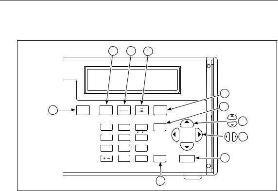
Input and Output Terminals
Figure 1-1 shows the Calibrator input and output terminals and explains their use.
|
|
|
2 |
3 |
|
|
|
|
|
|
VOLTS |
mA |
RTD |
|
|
|
|
|
|
|
100mA MAX |
|
|
|
|
|
|
|
|
|
HI |
HI |
|
|
|
|
|
|
|
1 |
OUTPUT |
|
|
STBY |
VOLTS |
TC |
|
TYPE |
|
100V MAX |
|
|
OPR |
mA |
RTD |
|
UNITS |
|
|
|
LO |
LO |
|
TC |
|
|
|
|
|
|
|
INPUT/OUTPUT |
|
|
|
|
|
||
|
20V PK |
|
|
|
OUTPUT |
INPUT |
ZERO |
|
|
|
MAX |
|
|
|
7 |
8 |
9 |
SHIFT |
|
|
|
|
|
|
|
||||
|
4W RTD |
|
|
|
SETUP |
CJC |
C / F |
|
|
|
HI |
|
|
|
4 |
5 |
6 |
|
|
|
|
|
20V PK |
SET |
RECALL |
AUTOSET |
|
|
|
|
|
|
|
|
|
||||
|
|
|
|
MAX |
1 |
2 |
3 |
|
|
|
INPUT |
SENSE |
|
|
|
|
|||
|
|
|
|
LOCAL |
EXP |
|
|
||
|
|
|
|
|
RNG LOCK |
|
|
||
|
LO |
|
|
|
/ |
0 |
• |
ENTER |
CE |
|
20V PK |
|
|
|
|
|
|
|
|
|
MAX |
|
|
|
|
|
|
|
|
|
6 |
|
5 |
4 |
|
|
|
|
|
|
|
|
|
|
|
|
|
|
fcn08f.eps |
No |
|
|
|
Description |
|
|
|
|
|
Terminals used to output DC Volts.
Terminals used to output DC current.
Terminals used to simulate RTDs and resistance.
Terminal for thermocouple input and simulation. The terminal accepts a miniature polarized thermocouple plug with flat, in-line blades spaced 7.9 mm (0.312 in) center to center.
Pressure module input.
Input terminals used to measure 4-wire RTD and resistance.
Figure 1-1. Input and Output Terminals and Connectors
1-5
525B
Users Manual
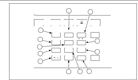
Using the Keys
Figure 1-2 shows the Calibrator pushbuttons and Table 1-3 explains their use. Other function keys are shown in Figure 1-3 and described in Table 1-4.
|
|
2 |
3 |
4 |
|
|
|
|
|
|
|
|
|
|
5 |
1 |
STBY |
VOLTS |
TC |
|
TYPE |
|
6 |
OPR |
mA |
RTD |
|
UNITS |
|
|
|
|
|
OUTPUT |
INPUT |
ZERO |
|
|
7 |
|
|
7 |
8 |
9 |
SHIFT |
|
|
|
|
SETUP |
CJC |
C / F |
|
|
8 |
|
|
4 |
5 |
6 |
|
|
|
|
|
SET |
RECALL |
AUTOSET |
|
|
|
|
|
1 |
2 |
3 |
|
|
|
|
|
RNG LOCK |
LOCAL |
EXP |
|
|
9 |
|
|
/ |
0 |
• |
ENTER |
CE |
|
|
|
|
|
|
10 |
|
|
|
|
Figure 1-2. Pushbuttons |
|
fcn09f.eps |
|||
|
|
|
|
||||
1-6
|
|
|
|
Getting Started |
1 |
|
|
|
|
|
Getting Acquainted with the Calibrator |
||
|
|
|
Table 1-3. Pushbutton Usage |
|
||
|
|
|
|
|
|
|
|
No |
Name |
|
Description |
|
|
|
|
|
|
|
|
|
|
|
|
|
Cycles the Calibrator through Standby and Operate |
|
|
|
|
modes. |
|
|
||
|
|
|
|
|
|
|
|
|
|
|
|
|
|
|
|
|
|
Toggles between DC voltage and DC current modes. |
|
|
|
|
|
|
|
|
|
|
|
|
|
Toggles between the current thermocouple and current |
|
|
|
|
RTD. |
|
|
||
|
|
|
|
|
|
|
|
|
|
|
|
|
|
|
|
|
|
Selects the pressure measurement mode. |
|
|
|
|
|
|
|
|
|
|
|
|
|
Selects a thermocouple or RTD type. For pressure |
|
|
|
|
|
measurement, this is used to select the pressure |
|
|
|
|
|
|
|
conversion units. |
|
|
|
|
|
|
|
|
|
|
|
|
|
Selects the alternate function above the numeric keys. |
|
|
|
|
|
|
|
|
|
|
|
|
|
• Increases or decreases the output level. |
|
|
|
|
|
|
• Also used to adjust LCD contrast and brightness and |
|
|
|
|
|
|
to select options on the Interface and Address |
|
|
|
|
|
|
menus. |
|
|
|
|
|
|
|
|
|
|
|
|
|
Selects a different digit to change. |
|
|
|
|
|
|
|
|
|
|
|
|
|
CE (Clear Entry) clears a partially completed keypad entry |
|
|
|
|
|
from the display. The display reverts to the last known |
|
|
|
|
|
|
|
good entry. |
|
|
|
|
|
|
|
|
|
|
|
|
|
Loads a newly entered output value into the Calibrator. |
|
|
|
|
|
|
The new value is an entry from the numeric keypad. Also |
|
|
|
|
used when entering custom RTD coefficients and when |
|
|
||
|
|
|
|
|
|
|
|
|
|
|
you adjust the display or contrast. |
|
|
|
|
|
|
|
|
|
1-7
525B
Users Manual
6 |
7 |
|
STBY |
|
|
VOLTS |
|
|
|
TC |
|
|
|
|
|
|
TYPE |
OPR |
|
|
mA |
|
|
|
RTD |
|
|
|
|
|
UNITS |
|
5 |
OUTPUT |
INPUT |
ZERO |
|
|
|
|||
|
7 |
8 |
9 |
SHIFT |
4 |
SETUP |
CJC |
C / F |
8 |
|
4 |
5 |
6 |
|
|
|
3 |
SET |
RECALL |
AUTOSET |
|
1 |
2 |
3 |
9 |
|
2 |
RNG LOCK |
LOCAL |
EXP |
||
|
|||||
|
/ |
0 |
• |
ENTER |
|
1 |
|
|
|
|
12 |
11 |
10 |
fcn11f.eps
Figure 1-3. Calibrator Function Keys
|
|
Table 1-4. Function Keys |
|
|
|
|
|
No |
Name |
Description |
|
|
|
|
|
|
RNG LOCK |
Activates/deactivates the autorange feature of the Calibrator in |
|
|
|||
|
Voltage source modes. |
||
|
|
|
|
|
SET |
Used to program a setpoint step for any output mode. |
|
|
|||
|
Key in the desired output and press . SETPOINT # appears |
||
|
|
on the display. Select a setpoint number from 1 to 9. The output you |
|
|
|
entered can now be recalled or used in the AUTOSET key |
|
|
|
described later in this manual. |
|
|
|
Each TC type, each RTD/OHMS type, mA, and Volts each have 9 |
|
|
|
programmable setpoints. |
|
|
|
|
|
|
CJC |
Toggles between the internal and external cold junction reference |
|
|
|||
|
locations. |
||
|
|
|
1-8
|
|
|
Getting Started |
1 |
|
|
|
|
Getting Acquainted with the Calibrator |
||
|
|
|
Table 1-4. Function Keys (cont) |
|
|
|
|
|
|
|
|
|
No |
Name |
Description |
|
|
|
|
|
|
|
|
|
|
SETUP |
Press to advance through the LCD Backlight, Interface, and |
|
|
|
|
|
|
||
|
|
Address menus. |
|
|
|
|
|
|
• Use and to adjust LCD backlight when the LCD menu is |
|
|
|
|
|
displayed. |
|
|
|
|
|
• Use and to toggle between Serial and GPIB interface when |
|
|
|
|
|
the Interface menu is displayed. |
|
|
|
|
|
• Use and to scroll from Address:1 to Address 30 when the |
|
|
|
|
|
address menu is displayed. |
|
|
|
|
|
|
|
|
|
|
OUTPUT |
Selects Output mode. |
|
|
|
|
|
|
||
|
|
|
|
|
|
|
|
|
|
|
|
|
|
INPUT |
Selects Input mode. |
|
|
|
|
|
|
|
|
|
|
|
|
|
|
|
|
ZERO |
Zeros the pressure module reading when in Pressure Measurement |
|
|
|
|
|
|
||
|
|
mode. |
|
|
|
|
|
|
Zeros the thermocouple TC mV/°C offset when in TC Measurement |
|
|
|
|
|
mode. |
|
|
|
|
|
|
|
|
|
|
°C/°F |
Toggles between Centigrade and Fahrenheit when you are using |
|
|
|
|
|
|
||
|
|
the TC or RTD functions. |
|
|
|
|
|
|
|
|
|
|
|
AUTOSET |
AUTOSET runs through the setpoints you entered using the SET |
|
|
|
|
|
|
||
|
|
function. Press . AUTO SET POINT? appears on the |
|
|
|
|
|
|
display. |
|
|
|
|
|
Enter a number between 1 and 9 that corresponds to the number of |
|
|
|
|
|
setpoints being used. DWELL TIME 5-500? appears on the display. |
|
|
|
|
|
Dwell time is the number of seconds between each setpoint. The |
|
|
|
|
|
output cycles through each setpoint and then reverses the order. |
|
|
|
|
|
For example, if 5 is entered for the number of setpoints, the |
|
|
|
|
|
Calibrator cycles through setpoints 1, 2, 3, 4, 5 and then reverses to |
|
|
|
|
|
setpoints 4, 3, 2, and 1. |
|
|
|
|
|
Caution |
|
|
|
|
|
Setpoints of 30 V or greater will not go to standby |
|
|
|
|
|
when you use this feature. |
|
|
|
|
|
|
|
|
|
|
EXP |
Enters an exponent when you define a custom RTD. |
|
|
|
|
|
|
||
|
|
|
|
|
|
|
|
|
|
|
|
1-9

525B
Users Manual
|
|
Table 1-4. Function Keys (cont) |
|
|
|
|
|
No |
Name |
Description |
|
|
|
|
|
|
RECALL |
Used to recall a programmed set point. |
|
|
|||
|
Press . RECALL SPT # appears on the display. Enter the |
||
|
|
number of the output setpoint that you want to use. The output will |
|
|
|
then be programmed to the setpoint you entered. |
|
|
|
|
|
|
LOCAL |
Used to regain local control of the Calibrator. If you set the |
|
|
|||
|
Calibrator to a remote state using the remote commands, all the |
||
|
|
front panel keys are locked out except the Local key. When you |
|
|
|
press the Local key, the front panel is unlocked. |
|
|
|
Note |
|
|
|
This function does not work when you set the Calibrator using the |
|
|
|
Remote with Lockout command. In Remote with Lockout mode, |
|
|
|
ALL keys are locked out and the Local key will not unlock the |
|
|
|
front panel. |
|
|
|
|
Display Error Messages
Table 1-5 lists informative messages that may appear on the front panel display. An explanation of each message is also provided.
|
Table 1-5. Display Error Messages |
|
|
Message |
Explanation |
|
|
OVER RANGE |
May be displayed in all output modes if you enter a value from the |
|
front panel keypad that exceeds the output range of the function. |
OVER LOAD |
May be displayed in V and mA output modes when the current is |
|
exceeded for volts and the resistance is exceeded for mA. |
OL |
Displayed in Input modes when the measured value exceeds the |
|
upper limit of the range. |
|
This error may also display in Output mode when the range is |
|
locked and an automatically recalled set point exceeds the locked |
|
range. For example, set point 1 (SP1) is set to 1V, SP2 is set to 2V, |
|
and SP3 is set to 100V, the range is locked to 10V range and the |
|
Calibrator is set up to automatically output the first 3 setpoints. |
|
When the Calibrator reaches SP3, the display reads OL, and the |
|
output is set to 0 for the duration of that setpoint. |
-OL |
Displayed in Input modes when the measured value exceeds the |
|
lower limit of the range. |
INITIALIZATION FAILURE |
Displayed when the Calibrator fails to power up properly. |
|
|
1-10
Getting Started 1
Getting Acquainted with the Calibrator
Rear Panel View
Figure 1-4 shows the features on the rear panel of the Calibrator and explains their use.
NO INTERNAL USER SERVICEABLE PARTS REFER SERVICE TO QUALIFIED
SERVICE PERSONNEL
FLUKE CORPORATION
MADE IN USA
PATENTS PENDING
www.fluke.com
C US
WARNING: FOR FIRE PROTECTION
REPLACE ONLY
WITH A 250V FUSE
OF INDICATED RATING?
MAINS SUPPLY |
FUSE |
47Hz - 63Hz |
||
15VA MAX |
||||
120V |
: 90V - 132V |
5x20mm0.25A 250V |
300V |
|
240V |
: 198V - 264V 5x20mm0.125A 250V |
|||
CAT |
||||
CHASSIS
GROUND
WARNING: TO AVOID ELECTRIC SHOCK
GROUNDING CONNECTOR IN POWER CORD
MUST BE CONNECTED
7 |
6 |
5 |
1 |
2 |
3 |
4 |
fcn10f.eps
No |
Description |
Power line fuse compartment. Contains fuses and line voltage selector.
The power switch turns the power on and off.
A grounded three-prong AC connector that accepts the line power cord.
The Chassis Ground terminal is internally connected to the ground prong of the AC connector.
Warning
To avoid shock hazard, connect the factory supplied threeconductor power cord to a properly grounded power outlet. Do not use a two-conductor adapter or extension cord; this will break the protective ground connection.
Use the rear panel CHASSIS GROUND terminal as a connection point for a protective grounding wire if there is any question about the effectiveness of instrument earth grounding through the line power cord ground wire.
Service port used to download new firmware to the Calibrator.
The IEEE-488 connector is a standard parallel interface for operating the 525B in remote control as a talker/listener on the IEEE-488 bus.
The RS-232 connector is used for serial remote control of the 525B.
Figure 1-4. Rear Panel View
1-11

525B
Users Manual
1-12
Chapter 2
Using Output Mode
Using Output Mode
In Output mode, the Calibrator generates calibrated signals for testing and calibrating process instruments. In Output mode, the Calibrator:
•supplies voltage, current, and resistance
•simulates the output of RTD and TC temperature sensors
Note
The OVER RANGE message displays if you enter an invalid output using the keypad. If you enter an out-of-range value, the Calibrator reverts to the last known good value. You do not need to press .
When adjusting an output using the keys, the Calibrator will not display or let you enter an out-of-range value.
Note
The figures is this chapter show how to connect to a Fluke 725 Multifunction Process Calibrator. For other instruments, refer to the users manual for connection instructions.
2-1

525B
Users Manual
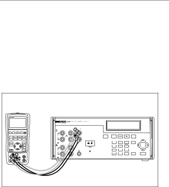
Simulating Thermocouple Temperature
Connect the Calibrator TC input/output to the unit under test (UUT) with thermocouple wire and the appropriate thermocouple mini-connector. Supported TC types are listed in Chapter 7. Figure 2-1 shows this connection.
To simulate temperature using a thermocouple (TC):
1.Attach the thermocouple extension wire as shown in Figure 2-1. One pin is wider than the other. Do not try to force a miniplug in the wrong polarization.
2.Press until TC is selected.
3.If necessary, press for TC OUT mode.
4.Press to select the desired thermocouple type.
5.Use the numeric keypad to enter the desired output value and press . You can also adjust the output value by pressing . Press to select a different digit to modify.
VOLTS |
mA |
RTD |
|
|
|
|
|
100mA MAX |
|
|
|
|
|
|
|
HI |
HI |
|
|
|
|
|
|
OUTPUT |
|
STBY |
VOLTS |
TC |
|
TYPE |
|
100V MAX |
|
OPR |
mA |
RTD |
|
UNITS |
|
LO |
LO |
TC |
|
|
|
|
|
INPUT/OUTPUT |
|
|
|
|
|
||
20V PK |
|
|
OUTPUT |
INPUT |
ZERO |
|
|
MAX |
|
|
7 |
8 |
9 |
SHIFT |
|
|
|
|
|
||||
4W RTD |
|
TC |
SETUP |
CJC |
C / F |
|
|
HI |
|
|
4 |
5 |
6 |
|
|
|
20V PK |
SET |
RECALL |
AUTOSET |
|
|
|
|
|
MAX |
1 |
2 |
3 |
|
|
INPUT |
SENSE |
|
|
|
|||
|
|
LOCAL |
EXP |
|
|
||
|
|
|
RNG LOCK |
|
|
||
LO |
|
|
/ |
0 |
• |
ENTER |
CE |
20V PK |
|
|
|
|
|
|
|
MAX |
|
|
|
|
|
|
|
fcn07f.eps
Figure 2-1. Connection to Simulate Thermocouple Temperature
2-2
Using Output Mode 2
Using Output Mode
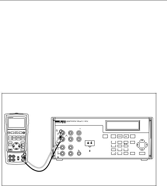
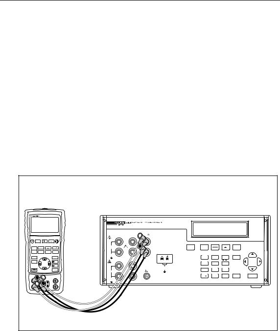
Simulating Temperature Using Resistance Temperature Detectors (RTDs)
RTDs have a characteristic resistance at specific temperatures. The simulated output, then, is a resistance value based on the selected temperature and type of RTD being simulated.
To simulate temperature using a resistance temperature detector:
1.Connect the Calibrator to the unit under test (UUT) as shown in Figure 2-2.
2.Press until RTD is selected.
3.If necessary, press for RTD OUT mode.
4.Press to select the desired RTD type.
5.Use the numeric keypad to enter the desired output value and press . You can also adjust the output value by pressing . Press to select a different digit to modify.
6.Press to activate output.
|
725 MULTIFUNCTION CALIBRATOR |
|
|
|
|
|
|
|
|
||
|
|
|
|
VOLTS |
mA |
RTD |
|
|
|
|
|
|
|
|
|
100mA MAX |
|
|
|
|
|
|
|
|
V mA |
|
ZERO |
HI |
HI |
|
|
|
|
|
|
|
LOOP |
|
|
|
|
|
|
|
|
||
|
|
|
|
OUTPUT |
|
STBY |
VOLTS |
TC |
|
TYPE |
|
MEAS |
V mA |
|
Hz |
100V MAX |
|
OPR |
mA |
RTD |
|
UNITS |
|
SOURCE |
|
°C °F |
LO |
LO |
TC |
|
|
|
|
|
|
|
TC |
RTD |
INPUT/OUTPUT |
|
|
|
|
|
|||
|
|
|
|
20V PK |
|
|
OUTPUT |
INPUT |
ZERO |
|
|
STORE |
|
|
|
MAX |
|
|
7 |
8 |
9 |
SHIFT |
|
SETUP |
|
|
100% |
|
|
|
|
||||
RECALL |
|
25% |
4W RTD |
|
|
SETUP |
CJC |
C / F |
|
|
|
|
|
|
|
HI |
|
|
4 |
5 |
6 |
|
|
|
|
|
25% |
|
|
SET |
RECALL |
AUTOSET |
|
|
|
|
|
|
|
|
20V PK |
|
|
||||
|
|
|
0% |
|
|
MAX |
1 |
2 |
3 |
|
|
|
|
|
INPUT |
SENSE |
|
|
|
||||
|
|
|
|
|
|
LOCAL |
EXP |
|
|
||
|
|
|
|
|
|
|
RNG LOCK |
|
|
||
|
|
|
|
LO |
|
|
/ |
0 |
• |
ENTER |
CE |
|
|
|
|
20V PK |
|
|
|
|
|
|
|
|
|
|
|
MAX |
|
|
|
|
|
|
|
|
|
|
|
|
|
|
|
|
|
|
fcn01f.eps |
Figure 2-2. Connection to Simulate a RTD Temperature
2-3

525B
Users Manual
Simulating Custom RTD Coefficients
The USR_DEF RTD type allows the Calibrator to simulate a custom curve-fit RTD.
To enter the coefficients for a custom RTD:
1.Press to select RTD mode.
2.Press until you get the USR_DEF display.
3.Press to enter custom RTD information. RTD CUSTOM (1-5) appears on the Calibrator display. You can store up to five custom RTD definitions on the Calibrator.
4.Press a number key to specify the RTD you want to define (1-5). You can press to step through definitions without changing the values.
5.When the SET/RECALL display appears, press to define a custom RTD coefficient.
6.Enter the MIN TEMP and press .
7.Enter the MAX TEMP and press .
8.Enter the nominal resistance (R0) and press .
9.Enter the temperature coefficients and press . Press to enter a positive or negative exponent for the coefficient.
To use a custom RTD:
1.Press to enter RTD mode.
2.Press until you get the USR_DEF display.
3.Press to use custom RTD information. RTD CUSTOM (1-5) appears on the Calibrator display. You can store up to five custom RTD definitions on the Calibrator.
4.Press a number key to select the RTD you want to use (1-5).
5.When the SET/RECALL display appears, press to recall and use the selected RTD.
2-4

Using Output Mode 2
Using Output Mode
Default RTD Coefficients
The USR_DEF function of the calibrator uses the Calendar-Van Dusen equation for outputting and measuring custom RTDs. The C coefficient is only used for the subrange –260 to 0 degrees Celsius. Only the A and B coefficients are needed for the subrange 0 to 630 degrees. The R0 is the resistance of the probe at 0 degrees Celsius. All of the USR_DEF will be set to PT385 as shown in Table 2-1.
|
|
Table 2-1. Default RTD Coefficients |
|
|||
|
|
|
|
|
|
|
|
Sub range |
|
R0 |
Coefficient A |
Coefficient B |
Coefficient C |
USR_DEF1 |
0 to 630 |
|
100 |
3.908X10⁻³ |
-5.775e-7 |
|
|
|
|
|
|
|
|
USR_DEF2 |
-260 to 0 |
|
100 |
3.908X10⁻³ |
-5.775e-7 |
-4.183e-12 |
|
|
|
|
|
|
|
USR_DEF3 |
0 to 630 |
|
100 |
3.908X10⁻³ |
-5.775e-7 |
|
|
|
|
|
|
|
|
USR_DEF4 |
-260 to 0 |
|
100 |
3.908X10⁻³ |
-5.775e-7 |
-4.183e-12 |
|
|
|
|
|
|
|
USR_DEF5 |
0 to 630 |
|
100 |
3.908X10⁻³ |
-5.775e-7 |
|
|
|
|
|
|
|
|
If other types of RTDs are required, Table 2-2 shows the coefficients for types PT391 and PT392. The C coefficient is only used for temperatures below 0 degrees Celsius.
Table 2-2. Other Commonly Used RTDs
RTD Type |
Coefficient A |
Coefficient B |
Coefficient C |
|
|
|
|
PT392 |
3.9848X10⁻³ |
-5.87X10⁻⁷ |
-4X10-12 |
|
|
|
|
PT391 |
3.9692X10⁻³ |
-5.8495X10⁻⁷ |
-4.2325X10⁻¹² |
|
|
|
|
The SPRT function of the calibrator uses ITS-90 standard coefficients for measuring a SPRT. Since the five coefficients are deviations all of them will be set to 0.
The coefficients A- and B- represent the A4 and B4 coefficient, obtained when the SPRT is calibrated at the triple points of argon, mercury and water. This covers the 83.8058K to 273.16K subrange. Coefficients A, B and C can represent different coefficients based on which subranges of the SPRT has been calibrated. For example, if the 273.15K to 933.473K subrange was used, A, B and C would represent A7, B7 and C7 whereas if the 273.15K to 692.67K subrange was used, A and B would represent A8 and B8 and C=0.
2-5

525B
Users Manual
Entering Custom Standard Platinum Resistance Thermometer (SPRT)
Coefficients
To enter coefficients for a custom SPRT:
1.Press to enter RTD mode.
2.Press until you get the RTD SPRT display and press .
3.Enter the MIN TEMP and press .
4.Enter the MAX TEMP and press .
5.Enter the nominal resistance (R0) and press .
6.Enter the temperature coefficients and press . Press to enter a positive or negative exponent for the coefficient.
2-6
Using Output Mode 2
Using Output Mode
Output DC Voltage
The Calibrator is a fully programmable precision source of DC voltage from 0 V to 100 V. The Calibrator can only output positive (+) values.
To output DC voltage:
1.Connect the Calibrator to the UUT as shown in Figure 2-3.
2.Press for V out display.
3.Use the numeric keypad to enter the desired output value and press . You can also adjust the output value by pressing . Press to select a different digit to modify.
4.Press to activate output.
Note
For safety purposes, the Calibrator resets to standby when output is set to 30 V or greater.
|
725 MULTIFUNCTION CALIBRATOR |
|
|
|
|
|
|
|
|
||
|
|
|
|
VOLTS |
mA |
RTD |
|
|
|
|
|
|
|
|
|
100mA MAX |
|
|
|
|
|
|
|
|
V mA |
|
ZERO |
HI |
HI |
|
|
|
|
|
|
|
LOOP |
|
|
|
|
|
|
|
|
||
|
|
|
|
OUTPUT |
|
STBY |
VOLTS |
TC |
|
TYPE |
|
MEAS |
V mA |
|
Hz |
100V MAX |
|
OPR |
mA |
RTD |
|
UNITS |
|
SOURCE |
|
°C °F |
LO |
LO |
TC |
|
|
|
|
|
|
|
TC |
RTD |
INPUT/OUTPUT |
|
|
|
|
|
|||
|
|
|
|
20V PK |
|
|
OUTPUT |
INPUT |
ZERO |
|
|
STORE |
|
|
|
MAX |
|
|
7 |
8 |
9 |
SHIFT |
|
SETUP |
|
|
100% |
|
|
|
|
||||
RECALL |
|
25% |
4W RTD |
|
|
SETUP |
CJC |
C / F |
|
|
|
|
|
|
|
HI |
|
|
4 |
5 |
6 |
|
|
|
|
|
25% |
|
|
SET |
RECALL |
AUTOSET |
|
|
|
|
|
|
|
|
20V PK |
|
|
||||
|
|
|
0% |
|
|
MAX |
1 |
2 |
3 |
|
|
|
|
|
INPUT |
SENSE |
|
|
|
||||
|
|
|
|
|
|
LOCAL |
EXP |
|
|
||
|
|
|
|
|
|
|
RNG LOCK |
|
|
||
|
|
|
|
LO |
|
|
/ |
0 |
• |
ENTER |
CE |
|
|
|
|
20V PK |
|
|
|
|
|
|
|
|
|
|
|
MAX |
|
|
|
|
|
|
|
|
|
|
|
|
|
|
|
|
|
|
fcn02f.eps |
Figure 2-3. Connection for Setting DC Voltage Output
2-7
525B
Users Manual
Output Resistance
To output resistance:
1.Connect the Calibrator to the UUT as shown in Figure 2-4.
2.Press until RTD mode is selected.
3.If necessary, press for RTD OUT mode.
4.Press to select the appropriate ohms output range (400 or 4000 ohms).
5.Use the numeric keypad to enter the desired output value and press . You can also adjust the output value by pressing . Press to select a different digit to modify.
6.Press to activate output.
Note
If the input current is excessive, the Calibrator will beep, display the message OVER LOAD, and enter Standby mode. You will need to check the input current and change it accordingly. Resistance specifications are listed in Chapter 7.
|
725 MULTIFUNCTION CALIBRATOR |
|
|
|
|
|
|
|
|
||
|
|
|
|
VOLTS |
mA |
RTD |
|
|
|
|
|
|
|
|
|
100mA MAX |
|
|
|
|
|
|
|
|
V mA |
|
ZERO |
HI |
HI |
|
|
|
|
|
|
|
LOOP |
|
|
|
|
|
|
|
|
||
|
|
|
|
OUTPUT |
|
STBY |
VOLTS |
TC |
|
TYPE |
|
MEAS |
V mA |
|
Hz |
100V MAX |
|
OPR |
mA |
RTD |
|
UNITS |
|
SOURCE |
|
°C °F |
LO |
LO |
TC |
|
|
|
|
|
|
|
TC |
RTD |
INPUT/OUTPUT |
|
|
|
|
|
|||
|
|
|
|
20V PK |
|
|
OUTPUT |
INPUT |
ZERO |
|
|
STORE |
|
|
|
MAX |
|
|
7 |
8 |
9 |
SHIFT |
|
SETUP |
|
|
100% |
|
|
|
|
||||
RECALL |
|
25% |
4W RTD |
|
|
SETUP |
CJC |
C / F |
|
|
|
|
|
|
|
HI |
|
|
4 |
5 |
6 |
|
|
|
|
|
25% |
|
|
SET |
RECALL |
AUTOSET |
|
|
|
|
|
|
|
|
20V PK |
|
|
||||
|
|
|
0% |
|
|
MAX |
1 |
2 |
3 |
|
|
|
|
|
INPUT |
SENSE |
|
|
|
||||
|
|
|
|
|
|
LOCAL |
EXP |
|
|
||
|
|
|
|
|
|
|
RNG LOCK |
|
|
||
|
|
|
|
LO |
|
|
/ |
0 |
• |
ENTER |
CE |
|
|
|
|
20V PK |
|
|
|
|
|
|
|
|
|
|
|
MAX |
|
|
|
|
|
|
|
|
|
|
|
|
|
|
|
|
|
|
fcn01f.eps |
Figure 2-4. Connection for Setting Resistance Output
2-8
Loading...