


®
54200
TV Signal Generator
Users Manual
4822 872 10182
November 1996, Rev. 4 4/98
© 1996 Fluke Corporation, All rights reserved. Printed in the Netherlands. All product names are trademarks of their respective companies.
Limited Warranty & Limitation of Liability
Each Fluke product is warranted to be free from defects in material and workmanship under normal use and service. The warranty period is one year and begins on the date of shipment. Parts, product repairs and services are warranted for 90 days. This warranty extends only to the original buyer or end-user customer of a Fluke authorized reseller, and does not apply to fuses, disposable batteries or to any product which, in Fluke's opinion, has been misused, altered, neglected or damaged by accident or abnormal conditions of operation or handling. Fluke warrants that software will operate substantially in accordance with its functional specifications for 90 days and that it has been properly recorded on non-defective media. Fluke does not warrant that software will be error free or operate without interruption.
Fluke authorized resellers shall extend this warranty on new and unused products to enduser customers only but have no authority to extend a greater or different warranty on behalf of Fluke. Warranty support is available if product is purchased through a Fluke authorized sales outlet or Buyer has paid the applicable international price. Fluke reserves the right to invoice Buyer for importation costs of repair/replacement parts when product purchased in one country is submitted for repair in another country.
Fluke's warranty obligation is limited, at Fluke's opinion, to refund of the purchase price, free of charge repair, or replacement of a defective product which is returned to an Fluke authorized service center within the warranty period.
To obtain warranty service, contact your nearest Fluke authorized service center or send the product, with a description of the difficulty, postage and insurance prepaid (FOB Destination), to the nearest Fluke authorized service center. Fluke assumes no risk for damage in transit. Following warranty repair, the product will be returned to Buyer, transportation prepaid (FOB Destination). If Fluke determines that the failure was caused by misuse, alteration, accident or abnormal condition of operation or handling, Fluke will provide an estimate of repair costs and obtain authorization before commencing the work. Following repair, the product will be returned to the Buyer transportation prepaid and the Buyer will be billed for the repair and return transportation charges (FOB Shipping Point).
THIS WARRANTY IS BUYER'S SOLE AND EXCLUSIVE REMEDY AND IS IN LIEU OF ALL OTHER WARRANTIES, EXPRESS OR IMPLIED, INCLUDING BUT NOT LIMITED TO ANY IMPLIED WARRANTY OF MERCHANTABILITY OR FITNESS FOR A PARTICULAR PURPOSE. FLUKE SHALL NOT BE LIABLE FOR ANY SPECIAL, INDIRECT, INCIDENTAL OR CONSEQUENTIAL DAMMAGES OR LOSSES, INCLUDING LOSS OF DATA, WHETHER ARISING FROM BREACH OF WARRANTY OR BASED ON CONTRACT, TORT, RELIANCE OR ANY OTHER THEORY.
Since some countries or states do not allow limitation of the term of an implied warranty, or exclusion or limitation of incidental or consequential damages, the limitations and exclusions of this warranty may not apply to every buyer. If any provision of this Warranty is held invalid or unenforceable by a court of competent jurisdiction, such holding will not affect the validity or enforceability of any other provision.
Fluke Corporation |
Fluke Industrial B.V. |
P.O. Box 9090 |
P.O. Box 90 |
Everett, WA |
7600 AB Almelo |
98206-9090 |
The Netherlands |
USA |
|
Service Centers
To locate an authorized service center, visit us on the World Wide Web:
http://www.fluke.com
or call Fluke using any of the phone numbers listed below:
+1-888-993-5853 in U.S.A. and Canada +31-402-675-200 in Europe +1-425-446-5500 from other countries

DECLARATION OF CONFORMITY for
Fluke
TV Signal Generator
54200
Manufacturer
Fluke Industrial B.V.
P.O. Box 90
7600 AB
Almelo
The Netherlands
Statement of Conformity
Based on test results using appropriate standards, the product is in conformity with Electromagnetic Compatibility Directive 89/336/EEC
Low Voltage Directive 73/23/EEC
Sample tests
Standards used:
EN 55011 (1992)
Radio Frequency Product-Family Emission Standard
EN 50082-1 (1992)
Electromagnetic Compatibility; Generic Immunity Standard:
IEC 801-2 (1984), IEC 801-3 (1984), IEC 801-4 (1988)
EN61000-4-2 (1995), EN61000-4-8(1993), ENV50140(1993)
EN 61010-1 (1994)+ A2 (1995)
Safety Requirements for Electrical Equipment for Measurement Use
The tests have been performed in a typical configuration.
This Conformity is indicated by the symbol  , i.e. “Conformité européenne”.
Table of Contents
Chapter |
Title |
Page |
1 |
Installation and Safety Instructions ................................................... |
1-1 |
|
Shipment Note ................................................................................................. |
1-5 |
|
Initial Inspection............................................................................................... |
1-5 |
|
Available built-in options Fluke 54200............................................................. |
1-5 |
|
Introduction...................................................................................................... |
1-9 |
|
Safety Instructions............................................................................................ |
1-9 |
|
Maintenance and Repair ............................................................................... |
1-9 |
|
Grounding (Earthing) ................................................................................... |
1-9 |
|
Power Cable, Line Voltage Range, and Fuses............................................... |
1-10 |
|
Operating Position of the Instrument ................................................................ |
1-11 |
|
Radio Interference Suppression ........................................................................ |
1-11 |
|
Isolation Transformer ....................................................................................... |
1-11 |
|
Instrucciones de instalación y de seguridad....................................................... |
1-13 |
|
Instrucciones de seguridad................................................................................ |
1-13 |
|
Mantenimiento y reparación ......................................................................... |
1-13 |
|
Puesta a tierra............................................................................................... |
1-13 |
|
Cable de conducción eléctrica, rango de tensiones de la linea y fusibles ....... |
1-14 |
|
Posición de uso del instrumento ....................................................................... |
1-15 |
|
Supresión de radiointerferencias ....................................................................... |
1-15 |
|
Transformador de aislamiento........................................................................... |
1-15 |
|
Istruzioni di installazione e di sicurezza............................................................ |
1-17 |
|
Istruzioni di sicurezza....................................................................................... |
1-17 |
|
Manutenzione e riparazione.......................................................................... |
1-17 |
|
Messa a terra ................................................................................................ |
1-17 |
|
Cavo elettrico, zona della tensione di rete et fusibili ..................................... |
1-18 |
|
Posizione di uso dell’apparecchio ..................................................................... |
1-19 |
|
Schermatura contro i radiodisturbi.................................................................... |
1-20 |
|
Trasformatore di separazione............................................................................ |
1-20 |
|
Opstellingsen veiligheidsinstructies................................................................ |
1-21 |
|
Veiligheidsinstructies ....................................................................................... |
1-21 |
|
Onderhoud en reparatie ................................................................................ |
1-21 |
i

54200
Users Manual
|
Aarding........................................................................................................ |
1-21 |
|
Stroomkabel, netspanningsgebied en zekeringen .......................................... |
1-22 |
|
Bedrijfsstand van het toestel ............................................................................. |
1-23 |
|
Ontstoring radio-interferentie............................................................................ |
1-24 |
|
Scheidingstransformator ................................................................................... |
1-24 |
|
Inledande anvisningar och säkerhetsanvisningar ............................................... |
1-25 |
|
Säkerhetsanvisningar........................................................................................ |
1-25 |
|
Underhåll och reparation .............................................................................. |
1-25 |
|
Jordning ....................................................................................................... |
1-25 |
|
Nätkabel, nätspänningsområde och säkringar................................................ |
1-26 |
|
Instrumentets driftsläge .................................................................................... |
1-27 |
|
Radio-avstörning .............................................................................................. |
1-27 |
|
Skiljetransformator........................................................................................... |
1-27 |
2 |
Main Features....................................................................................... |
2-1 |
|
Introduction...................................................................................................... |
2-3 |
|
Main Features................................................................................................... |
2-3 |
3 |
Getting Started..................................................................................... |
3-1 |
|
Introduction...................................................................................................... |
3-3 |
|
Getting Started ................................................................................................. |
3-3 |
|
General Information ..................................................................................... |
3-3 |
|
Turning the Instrument on ............................................................................ |
3-3 |
|
Self-test Routine............................................................................................... |
3-3 |
|
Brief Checking Procedure................................................................................. |
3-4 |
|
Test Equipment:........................................................................................... |
3-4 |
|
Instrument Settings and Checks.................................................................... |
3-4 |
|
Operation and Application................................................................................ |
3-13 |
|
Control Elements, Display and Connectors................................................... |
3-13 |
|
Front Panel .............................................................................................. |
3-13 |
|
Rear Panel................................................................................................ |
3-17 |
4 |
How to Use the Instrument.................................................................. |
4-1 |
|
Introduction...................................................................................................... |
4-3 |
|
Operating via Keyboard.................................................................................... |
4-3 |
|
General Information ..................................................................................... |
4-3 |
|
Display .................................................................................................... |
4-3 |
|
Keyboard ................................................................................................. |
4-6 |
|
Instrument Settings ...................................................................................... |
4-7 |
|
TV Standard............................................................................................. |
4-7 |
|
Video Settings.......................................................................................... |
4-10 |
|
Sound Settings ......................................................................................... |
4-12 |
|
Teletext, VPS, PDC, CC, and WSS.......................................................... |
4-14 |
|
Vision Carrier Frequency Settings (RF Carrier)........................................ |
4-15 |
|
Vision Carrier Level Setting (RF Level)................................................... |
4-18 |
|
Video Amplitude Setting.......................................................................... |
4-22 |
|
Chroma Amplitude Setting....................................................................... |
4-26 |
|
Test Patterns ............................................................................................ |
4-30 |
|
Storing and Recalling of Settings ................................................................. |
4-35 |
|
Storing of Instrument Settings.................................................................. |
4-35 |
|
Recalling of Instrument Settings .............................................................. |
4-37 |
|
Digital Data and Text............................................................................... |
4-39 |
ii
|
|
Contents (continued) |
|
Description and Applications of the Test Patterns............................................. |
4-40 |
|
Circle ........................................................................................................ |
4-42 |
|
Center Cross with Border Castellations ........................................................ |
4-43 |
|
Dots ........................................................................................................ |
4-45 |
|
Crosshatch ................................................................................................... |
4-46 |
|
Checkerboard ............................................................................................... |
4-47 |
|
White Pattern ............................................................................................... |
4-48 |
|
Multiburst .................................................................................................... |
4-48 |
|
Greyscale ..................................................................................................... |
4-49 |
|
DEM Pattern ................................................................................................ |
4-49 |
|
DEM 1 (PAL) .......................................................................................... |
4-49 |
|
DEM 1 (NTSC)........................................................................................ |
4-51 |
|
DEM 1 (SECAM) .................................................................................... |
4-52 |
|
DEM 2 (PAL) .......................................................................................... |
4-53 |
|
DEM 2 (NTSC)........................................................................................ |
4-53 |
|
DEM 2 (SECAM) .................................................................................... |
4-54 |
|
Purity ........................................................................................................ |
4-55 |
|
PLUGE ........................................................................................................ |
4-56 |
|
Color Bar ..................................................................................................... |
4-57 |
|
Full Field Color Bar................................................................................. |
4-57 |
|
Split Field Color Bar................................................................................ |
4-58 |
|
SMPTE Color Bar.................................................................................... |
4-59 |
|
Horizontal Color Bar................................................................................ |
4-60 |
|
Color Temperature Adjustment .................................................................... |
4-60 |
|
VCR Test..................................................................................................... |
4-62 |
|
VCR 1 .................................................................................................... |
4-62 |
|
VCR 2 .................................................................................................... |
4-63 |
|
Standard Resolution Test ......................................................................... |
4-64 |
|
High Resolution Test ............................................................................... |
4-64 |
|
Writing Current Adjustment..................................................................... |
4-64 |
|
Digital Scan Test.......................................................................................... |
4-64 |
|
ADC Check 1........................................................................................... |
4-65 |
|
ADC Check 2........................................................................................... |
4-66 |
|
Moving Block.......................................................................................... |
4-67 |
|
Progressive Scan Check 1 ........................................................................ |
4-67 |
|
Progressive Scan Check 2 ........................................................................ |
4-68 |
|
Progressive Scan Check 3 ........................................................................ |
4-68 |
|
DIVERSE .................................................................................................... |
4-69 |
|
EHT Test ................................................................................................. |
4-69 |
|
IRS17 .................................................................................................... |
4-70 |
|
Combined Test Patterns................................................................................ |
4-71 |
|
CIRCLE................................................................................................... |
4-71 |
|
Twofold Combinations of Patterns ........................................................... |
4-71 |
|
Threefold Combinations of Patterns ......................................................... |
4-73 |
|
Fourfold Combinations of Patterns........................................................... |
4-73 |
|
Insertion-Reference Signal (IRS).................................................................. |
4-74 |
5 |
Function Reference ............................................................................. |
5-1 |
|
TELETEXT...................................................................................................... |
5-3 |
|
General ........................................................................................................ |
5-3 |
|
UK-Teletext ............................................................................................. |
5-3 |
|
TOP (Table of Pages)............................................................................... |
5-3 |
|
FLOF (Full Level-One Features) / FASTEXT .......................................... |
5-5 |
|
VPT (Video Recorder Programming by Teletext)..................................... |
5-5 |
iii

54200
Users Manual
Video Recorder Programming by Teletext with PSF ................................ |
5-7 |
Contents of Teletext Pages TOP/FLOF .................................................... |
5-9 |
DIDON ANTIOPE Teletext ......................................................................... |
5-10 |
Contents of DIDON ANTIOPE Text Pages.............................................. |
5-10 |
Operating ................................................................................................. |
5-12 |
Checking and Adjusting........................................................................... |
5-13 |
Wide Screen Signalling (WSS)......................................................................... |
5-14 |
General ........................................................................................................ |
5-14 |
Operating ................................................................................................. |
5-15 |
WSS Auto Mode...................................................................................... |
5-16 |
WSS Manual Mode.................................................................................. |
5-17 |
Status Bits Transmission Scheme for Wide Screen Signalling .................. |
5-18 |
Programming the Real Time Clock................................................................... |
5-20 |
PDC and VPS................................................................................................... |
5-22 |
General ........................................................................................................ |
5-22 |
PDC Description .......................................................................................... |
5-22 |
Operating ................................................................................................. |
5-23 |
VPS Description........................................................................................... |
5-26 |
Operating ................................................................................................. |
5-27 |
Data Format of Programme Delivery Data in the TV Line 16................... |
5-30 |
CLOSED CAPTION (CC) ............................................................................... |
5-32 |
General ........................................................................................................ |
5-32 |
Operating ................................................................................................. |
5-34 |
Memory Contents .................................................................................... |
5-35 |
Analog Mono Sound ........................................................................................ |
5-38 |
General ........................................................................................................ |
5-38 |
Operating ................................................................................................. |
5-38 |
Analog Stereo/Dual Sound ............................................................................... |
5-39 |
General ........................................................................................................ |
5-39 |
Operating ................................................................................................. |
5-40 |
NICAM Sound ................................................................................................. |
5-42 |
The NICAM-728 Transmission Mode ...................................................... |
5-42 |
Operating ................................................................................................. |
5-44 |
Applications............................................................................................. |
5-46 |
Test functions .......................................................................................... |
5-46 |
BTSC Sound .................................................................................................... |
5-48 |
General ........................................................................................................ |
5-48 |
Definitions ............................................................................................... |
5-50 |
Operating ................................................................................................. |
5-50 |
Explanations of BTSC Test Modes .......................................................... |
5-53 |
Applications............................................................................................. |
5-54 |
Recommendations.................................................................................... |
5-55 |
Sound Operating Modes ................................................................................... |
5-56 |
External Modulation......................................................................................... |
5-60 |
External Video Modulation .......................................................................... |
5-60 |
Operating ................................................................................................. |
5-61 |
External Sound Modulation.......................................................................... |
5-61 |
Operating ................................................................................................. |
5-63 |
Synchronization Outputs and Triggering ...................................................... |
5-64 |
Operating Hints, Out of Range and Error Messages .......................................... |
5-65 |
Operating Hints............................................................................................ |
5-65 |
Out of Range Messages................................................................................ |
5-65 |
Error Messages............................................................................................. |
5-66 |
Remote Control Specific Error Messages ..................................................... |
5-66 |
iv
|
|
Contents (continued) |
6 |
Remote Control.................................................................................... |
6-1 |
|
Introduction...................................................................................................... |
6-3 |
|
IEEE-488 Interface........................................................................................... |
6-3 |
|
Instrument Address ...................................................................................... |
6-3 |
|
Interface Functions....................................................................................... |
6-6 |
|
RS-232 Interface .............................................................................................. |
6-7 |
|
Instrument Configuration ............................................................................. |
6-7 |
|
Interface Functions and Wiring..................................................................... |
6-11 |
|
Interface Functions....................................................................................... |
6-12 |
|
Remote Control Commands ............................................................................. |
6-13 |
|
Program Message Syntax ............................................................................. |
6-13 |
|
Message Terminator..................................................................................... |
6-13 |
|
Service Request (SRQ) and Status Registers................................................. |
6-14 |
|
54200 ‘Standard Event Status Register’.................................................... |
6-15 |
|
Common Commands and Queries (IEEE-488.2)........................................... |
6-16 |
|
System Data............................................................................................. |
6-16 |
|
Internal Operations................................................................................... |
6-17 |
|
Synchronization ....................................................................................... |
6-19 |
|
Status and Event ...................................................................................... |
6-20 |
|
Save and Recall Instrument Settings......................................................... |
6-21 |
|
Device Specific Messages ............................................................................ |
6-21 |
|
Vision Carrier .......................................................................................... |
6-22 |
|
TV-System............................................................................................... |
6-23 |
|
Video .................................................................................................... |
6-25 |
|
Sound .................................................................................................... |
6-31 |
|
Digital Services........................................................................................ |
6-35 |
|
Miscellaneous commands......................................................................... |
6-39 |
|
Device Setting Queries............................................................................. |
6-40 |
|
Programming Examples ................................................................................... |
6-43 |
|
Example for the IEEE-488 Interface ............................................................. |
6-43 |
|
Example for the RS-232 Interface................................................................. |
6-46 |
|
Error Messages................................................................................................. |
6-50 |
|
Conversion Table for the PM 5415/18 Command Set to 54200 Commands ...... |
6-51 |
7 |
Specifications ...................................................................................... |
7-1 |
|
Safety and EMC Requirements......................................................................... |
7-3 |
|
Performance Characteristics and Specifications ................................................ |
7-3 |
|
Video and RF ................................................................................................... |
7-4 |
|
Outputs ........................................................................................................ |
7-4 |
|
CVBS Video............................................................................................ |
7-4 |
|
CVBS SYNC, LINE SYNC and FIELD Synchronization......................... |
7-4 |
|
EURO AV Control Voltages .................................................................... |
7-4 |
|
Terrestrial RF Carrier............................................................................... |
7-5 |
|
Video Modulation .................................................................................... |
7-6 |
|
Inputs ........................................................................................................ |
7-6 |
|
Video IN.................................................................................................. |
7-6 |
|
Video ........................................................................................................ |
7-7 |
|
Synchronization ....................................................................................... |
7-7 |
|
Luminance ............................................................................................... |
7-7 |
|
Chrominance............................................................................................ |
7-7 |
|
Patterns.................................................................................................... |
7-8 |
|
Sound ............................................................................................................ |
7-10 |
|
Outputs ........................................................................................................ |
7-10 |
|
Sound Carrier........................................................................................... |
7-10 |
v

54200
Users Manual
|
Audio and Euro AV ................................................................................. |
7-10 |
|
BTSC MPX and FM Stereo Pilot ............................................................. |
7-10 |
|
NICAM Data and NICAM Clock............................................................. |
7-11 |
|
Inputs ........................................................................................................ |
7-11 |
|
Audio, Euro AV and MTS Multiplex ....................................................... |
7-11 |
|
Mono ........................................................................................................ |
7-11 |
|
Sound Carrier........................................................................................... |
7-11 |
|
Modulation .............................................................................................. |
7-12 |
|
Stereo /Dual ................................................................................................. |
7-12 |
|
Sound Carrier 1........................................................................................ |
7-12 |
|
Sound Carrier 2........................................................................................ |
7-12 |
|
Modulation .............................................................................................. |
7-13 |
|
Identification/Subcarrier........................................................................... |
7-13 |
|
NICAM Stereo............................................................................................. |
7-13 |
|
Sound Carrier 1........................................................................................ |
7-13 |
|
Sound Carrier 2........................................................................................ |
7-14 |
|
Modulation .............................................................................................. |
7-14 |
|
BTSC Stereo ................................................................................................ |
7-14 |
|
Sound Carrier........................................................................................... |
7-14 |
|
Modulation .............................................................................................. |
7-15 |
|
Identification............................................................................................ |
7-15 |
|
Digital Services ................................................................................................ |
7-16 |
|
Wide Screen Signalling (WSS)..................................................................... |
7-16 |
|
Teletext DIDON ANTIOPE (CCIR System A)............................................. |
7-16 |
|
Teletext UK (CCIR System B) ..................................................................... |
7-17 |
|
PDC ........................................................................................................ |
7-17 |
|
VPS ........................................................................................................ |
7-17 |
|
Closed Caption............................................................................................. |
7-18 |
|
RGB, YC (S-VHS/Hi-8), YCrCb Outputs ........................................................ |
7-19 |
|
RGB Outputs ............................................................................................... |
7-19 |
|
YC Outputs.................................................................................................. |
7-19 |
|
YCrCb Outputs ............................................................................................ |
7-19 |
|
Feedthrough Connection .............................................................................. |
7-20 |
|
IEEE-488 and RS-232 Interface........................................................................ |
7-20 |
|
IEEE-488 Interface....................................................................................... |
7-20 |
|
RS-232 Interface .......................................................................................... |
7-20 |
|
General Specifications...................................................................................... |
7-21 |
|
Environmental Conditions............................................................................ |
7-21 |
|
Power Requirements .................................................................................... |
7-22 |
|
Dimensions and Weight ............................................................................... |
7-22 |
|
Accessories ...................................................................................................... |
7-23 |
|
Standard....................................................................................................... |
7-23 |
|
Optional ....................................................................................................... |
7-24 |
8 |
Brief Functional Test ........................................................................... |
8-1 |
|
Brief Functional Test........................................................................................ |
8-3 |
|
Introduction.................................................................................................. |
8-3 |
|
Recommended Test Equipment .................................................................... |
8-3 |
|
Self-Test Routine ......................................................................................... |
8-4 |
|
Function Verification........................................................................................ |
8-5 |
|
TV Standard PAL......................................................................................... |
8-5 |
|
Video Part, using RF Connection ............................................................. |
8-5 |
|
Video Part, using Y/C Connection (S-VHS, Hi-8).................................... |
8-7 |
|
Sound Part ............................................................................................... |
8-8 |
vi
|
|
Contents (continued) |
|
Teletext, VPS, PDC, and WSS (Digital Services)..................................... |
8-12 |
|
Wide Screen Signalling Bits (WSS .......................................................... |
8-14 |
|
TV Standard NTSC...................................................................................... |
8-15 |
|
Video Part, using RF Connection ............................................................. |
8-15 |
|
Video Part, using Y/C Connection (S-VHS, Hi-8).................................... |
8-17 |
|
Sound Part ............................................................................................... |
8-18 |
|
Closed Caption (Digital Service CC)........................................................ |
8-21 |
|
TV Standard SECAM................................................................................... |
8-23 |
|
Video Part, using RF Connection ............................................................. |
8-23 |
|
Video Part, using Y/C Connection (S-VHS, Hi-8).................................... |
8-25 |
|
Sound Part ............................................................................................... |
8-26 |
|
Teletext, VPS, PDC, and WSS (Digital Services)..................................... |
8-29 |
Appendices |
|
|
A |
TV Systems Used in Various Countries ............................................... |
A-1 |
B |
VHF/UHF-Channel Frequencies for Different TV Systems .................. |
B-1 |
C |
Default Settings for Countries.............................................................. |
C-1 |
D |
Spectras of TV Audio Systems............................................................. |
D-1 |
E |
Nomenclature of Color Bar Signals...................................................... |
E-1 |
F |
Menu Trees.......................................................................................... |
F-1 |
G |
Pattern Popup Menus ........................................................................... |
G-1 |
Index
vii
List of Tables
Table |
Title |
Page |
1-1. |
Display Indication of built-in Options.................................................................. |
1-8 |
1-2. |
Delivered Power Cable ........................................................................................ |
1-10 |
1-3. |
Cable suministrado .............................................................................................. |
1-14 |
1-4. |
Cavo di alimentatione fornito in dotazione........................................................... |
1-18 |
1-5. |
Meegelverde netkabel .......................................................................................... |
1-22 |
1-6. |
Medleverera nätkabel........................................................................................... |
1-26 |
3-1. |
EURO AV IN...................................................................................................... |
3-19 |
3-2. |
EURO AV OUT .................................................................................................. |
3-19 |
3-3. |
Y/C OUT............................................................................................................. |
3-19 |
4-1. |
Circle .................................................................................................................. |
4-42 |
4-2. |
Center Cross........................................................................................................ |
4-44 |
4-3. |
Dots..................................................................................................................... |
4-45 |
4-4. |
Crosshatch........................................................................................................... |
4-47 |
4-5. |
PLUGE ............................................................................................................... |
4-56 |
4-6. |
Full Field Color Bar ............................................................................................ |
4-57 |
4-7. |
Color Temperature Adjustment............................................................................ |
4-60 |
4-7. |
Color Temperature Adjustment............................................................................ |
4-61 |
4-8. |
VCR 1................................................................................................................. |
4-62 |
5-1. |
TOP Teletext Remote Control ............................................................................. |
5-4 |
5-2. |
PDC/VPT Teletext Page 300, Transport Method A.............................................. |
5-6 |
5-3. |
PDC/VPT Teletext Page 300, Transport Method B.............................................. |
5-7 |
5-4. |
DIDON ANTIOPE Text Pages ............................................................................ |
5-10 |
5-5. |
Teletext Systems and Modes................................................................................ |
5-12 |
5-6. |
WSS Auto Mode ................................................................................................. |
5-16 |
5-7. |
WSS Status Bits Transmission Scheme ............................................................... |
5-18 |
5-8. |
VPS Information ................................................................................................. |
5-26 |
5-9. |
Data Format of Programme Delivery Data in the TV Line 16 .............................. |
5-30 |
5-9. |
Data Format of Programme Delivery Data in the TV Line 16 (cont) .................... |
5-31 |
5-10. Closed Caption Field Packets .............................................................................. |
5-33 |
|
5-11. Analog Stereo/Dual Audio Signals, Systems B/G and D/K .................................. |
5-39 |
|
5-12. |
Analog Stereo/Dual Audio Signals, System Mk (Korean Stereo) ......................... |
5-40 |
5-13. 54200 Analog Stereo/Dual Sound Systems .......................................................... |
5-40 |
|
5-14. NICAM-728 Transmission, 54200 NICAM Systems ........................................... |
5-42 |
|
5-15. BTSC Sound Carrier Modulation Standards......................................................... |
5-49 |
|
5-16. |
54200 BTSC Sound Systems............................................................................... |
5-50 |
ix

54200
Users Manual
5-17. |
Sound Operating Modes ...................................................................................... |
5-56 |
5-18. |
Sound Operating Modes (cont) ............................................................................ |
5-57 |
5-18. |
Sound Operating Modes (cont) ............................................................................ |
5-58 |
5-18. |
Sound Operating Modes (cont) ............................................................................ |
5-59 |
5-18. |
External Video Modulation Modes ...................................................................... |
5-60 |
5-19. |
External Sound Mode .......................................................................................... |
5-62 |
6-1. |
Fluke 54200 'Status Byte Register'....................................................................... |
6-14 |
6-2. |
Instrument Default Settings after Reset (*RST) ................................................... |
6-17 |
6-3. |
Telephone Country Code ..................................................................................... |
6-23 |
6-4. |
Conversion Table ................................................................................................ |
6-51 |
x
Chapter 1
Installation and Safety Instructions
Title |
Page |
Shipment Note ................................................................................................. |
1-5 |
Initial Inspection............................................................................................... |
1-5 |
Available built-in options Fluke 54200............................................................. |
1-5 |
Introduction...................................................................................................... |
1-9 |
Safety Instructions............................................................................................ |
1-9 |
Maintenance and Repair ............................................................................... |
1-9 |
Grounding (Earthing) ................................................................................... |
1-9 |
Power Cable, Line Voltage Range and Fuses................................................ |
1-10 |
Operating Position of the Instrument ................................................................ |
1-11 |
Radio Interference Suppression ........................................................................ |
1-11 |
Isolation Transformer ....................................................................................... |
1-11 |
Instrucciones de instalación y de seguridad....................................................... |
1-13 |
Instrucciones de seguridad................................................................................ |
1-13 |
Mantenimiento y reparación ......................................................................... |
1-13 |
Puesta a tierra............................................................................................... |
1-13 |
Cable de conducción eléctrica, rango de tensiones de la linea y fusibles ....... |
1-14 |
Posición de uso del instrumento ....................................................................... |
1-15 |
Supresión de radiointerferencias ....................................................................... |
1-15 |
Transformador de aislamiento........................................................................... |
1-15 |
Istruzioni di installazione e di sicurezza............................................................ |
1-17 |
Istruzioni di sicurezza....................................................................................... |
1-17 |
Manutenzione e riparazione.......................................................................... |
1-17 |
Messa a terra ................................................................................................ |
1-17 |
Cavo elettrico, zona della tensione di rete et fusibili ..................................... |
1-18 |
Posizione di uso dell’apparecchio ..................................................................... |
1-19 |
Schermatura contro i radiodisturbi.................................................................... |
1-20 |
Trasformatore di separazione............................................................................ |
1-20 |
1-1

54200
Users Manual
Opstellingsen veiligheidsinstructies ............................................................... |
1-21 |
Veiligheidsinstructies....................................................................................... |
1-21 |
Onderhoud en reparatie................................................................................ |
1-21 |
Aarding ....................................................................................................... |
1-21 |
Stroomkabel, netspanningsgebied en zekeringen.......................................... |
1-22 |
Bedrijfsstand van het toestel ............................................................................ |
1-23 |
Otnstoring radio-interferentie........................................................................... |
1-24 |
Scheidingstransformator .................................................................................. |
1-24 |
Inledande anvisningar och säkerhetsanvisningar............................................... |
1-25 |
Säkerhetsanvisningar ....................................................................................... |
1-25 |
Underhåll och reparation.............................................................................. |
1-25 |
Jordning ...................................................................................................... |
1-25 |
Nätkabel, nätspänningsområde och säkringar............................................... |
1-26 |
Instrumentets driftsläge.................................................................................... |
1-27 |
Radio-avstörning ............................................................................................. |
1-27 |
Skiljetransformator .......................................................................................... |
1-27 |
1-2

|
|
|
|
|
|
|
|
|
|
|
|
|
|
|
|
|
|
|
|
|
|
|
|
|
|
|
|
|
|
|
|
|
|
|
|
|
|
|
|
|
|
|
|
|
|
|
|
|
|
|
|
|
|
|
Installation and Safety Instructions |
1 |
||||||||||||||||||||||||||||||||||||||||||||||||||||||||||||||||||||||||||||||||||||||||||||||||||
GB |
|
|
|
|
|
|
|
|
|
|
|
|
|
|
|
|
|
|
|
|
|
|
|
|
|
|
|
|
|
|
|
|
|
|
|
|
|
|
|
|
|
|
|
|
|
|
|
|
|
|
|
|
|
|
|
|
|
|
|
|
|
|
|
|
|
|
|
|
|
|
|
|
|
|
|
|
|
|
|
|
|
|
|
|
|
|
|
|
|
|
|
|
|
|
|
|
|
|
|
|
Shipment Note |
|||||||||||||||||||||||||||||||||||||||||||||||||||||
|
|
|
|
|
|
|
|
|
|
|
|
|
|
|
|
|
|
|
|
|
|
|
|
|
|
|
|
|
|
|
|
|
|
|
|
|
|
|
|
|
|
|
|
|
|
|
|
|
|
|
|
|
|
|
|
|
|
|
|
|
|
|
|
|
|
|
|
|
|
|
|
|
|
|
|
|
|
|
|
|
|
|
|
|
|
|
|
|
|
|
|
|
|
|
|
|
|
|
|
|
|
|
|
|
|
|
|
|
|
|
|
|
|
|
|
|
|
|
|
|
|
|
|
|
|
|
|
|
|
|
|
|
|
|
|
|
|
|
|
|
|
|
|
|
|
|
|
|
|
|
|
|
|
|
|
|
|
|
|
|
|
|
|
|
|
|
|
|
|
|
|
|
|
|
|
|
|
|
|
|
|
|
|
|
|
|
|
|
|
|
|
|
|
|
|
|
|
|
|
|
|
|
|
|
|
|
|
|
|
|
|
|
|
|
|
|
|
|
|
|
|
|
|
|
|
|
|
|
|
|
|
|
|
|
|
|
|
|
|
|
|
|
|
|
|
|
|
|
|
|
|
|
|
|
|
|
|
|
|
|
|
|
|
|
|
|
|
|
|
|
|
|
|
|
|
|
|
|
|
|
|
|
|
|
|
|
|
|
|
|
|
|
|
|
|
|
|
|
|
|
|
|
|
|
|
|
|
|
|
|
|
|
|
|
|
|
|
|
|
|
|
|
|
|
|
|
|
|
|
|
|
|
|
|
|
|
|
|
|
|
|
|
|
|
|
|
|
|
|
|
|
|
|
|
|
|
|
|
|
|
|
|
|
|
|
|
|
|
|
|
|
|
|
|
|
|
|
|
|
|
|
|
|
|
|
|
|
|
|
|
|
|
|
|
|
|
|
|
|
|
|
|
|
|
|
|
|
|
|
|
|
|
|
|
|
|
|
|
|
|
|
|
|
|
|
|
|
|
|
|
|
|
|
|
|
|
|
|
|
|
|
|
|
|
|
|
|
|
|
|
|
|
|
|
|
|
|
|
|
|
|
|
|
|
|
|
|
|
|
|
|
|
|
|
|
|
|
|
|
|
|
|
|
|
|
|
|
|
|
|
|
|
|
|
|
|
|
|
|
|
|
|
|
|
|
|
|
|
|
|
|
|
|
|
|
|
|
|
|
|
|
|
|
|
|
|
|
|
|
|
|
|
|
|
|
|
|
|
|
|
|
|
|
|
|
|
|
|
|
|
|
|
|
|
|
|
|
|
|
|
|
|
|
|
|
|
|
|
|
|
|
|
|
|
|
|
|
|
|
|
|
|
|
|
|
|
|
|
|
|
|
|
|
|
|
|
|
|
|
|
|
|
|
|
|
|
|
|
|
|
|
|
|
|
|
|
|
|
|
|
|
|
|
|
|
|
|
|
|
|
|
|
|
|
|
|
|
|
|
|
|
|
|
|
|
|
|
|
|
|
|
|
|
|
|
|
|
|
|
|
|
|
|
|
|
|
|
|
|
|
|
|
|
|
|
|
|
|
|
|
|
|
|
|
|
|
|
|
|
|
|
|
|
|
|
|
|
|
|
|
|
|
|
|
|
|
|
|
|
|
|
|
|
|
|
|
|
|
|
|
|
|
|
|
|
|
|
|
|
|
|
|
|
|
|
|
|
|
|
|
|
|
|
|
|
|
|
|
|
|
|
|
|
|
|
|
|
|
|
|
|
|
|
|
|
|
|
|
|
|
|
|
|
|
|
|
|
|
|
|
|
|
|
|
|
|
|
|
|
|
|
|
|
|
|
|
|
|
|
|
|
|
|
|
|
|
|
|
|
|
|
|
|
|
|
|
|
|
|
|
|
|
|
|
|
|
|
|
|
|
|
|
|
|
|
|
|
|
|
|
|
|
|
|
|
|
|
|
|
|
|
|
|
|
|
|
|
|
|
|
|
|
|
|
|
|
|
|
|
|
|
|
|
|
|
|
|
|
|
|
|
|
|
|
|
|
|
|
|
|
|
|
|
|
|
|
|
|
|
|
|
|
|
|
|
|
|
|
|
|
|
|
|
|
|
|
|
|
|
|
|
|
|
|
|
|
|
|
|
|
|
|
|
|
|
|
|
|
|
|
|
|
|
|
|
|
|
|
|
|
|
|
|
|
|
|
|
|
|
|
|
|
|
|
|
|
|
|
|
|
|
|
|
|
|
|
|
|
|
|
|
|
|
|
|
|
|
|
|
|
|
|
|
|
|
|
|
|
|
|
|
|
|
|
|
|
|
|
|
|
|
|
|
|
|
|
|
|
|
|
|
|
|
|
|
|
|
|
|
|
|
|
|
|
|
|
|
|
|
|
|
|
|
|
|
|
|
|
|
|
|
|
|
|
|
|
|
|
|
|
|
|
|
|
|
|
|
|
|
|
|
|
|
|
|
|
|
|
|
|
|
|
|
|
|
|
|
|
|
|
|
|
|
|
|
|
|
|
|
|
|
|
|
|
|
|
|
|
|
|
|
|
|
|
|
|
|
|
|
|
|
|
|
|
|
|
|
|
|
|
|
|
|
|
|
|
|
|
|
|
|
|
|
|
|
|
|
|
|
|
|
|
|
|
|
|
|
|
|
|
|
|
|
|
|
|
|
|
|
|
|
|
|
|
|
|
|
|
|
|
|
|
|
|
|
|
|
|
|
|
|
|
|
|
|
|
|
|
|
|
|
|
|
|
|
|
|
|
|
|
|
|
|
|
|
|
|
|
|
|
|
|
|
|
|
|
|
|
|
|
|
|
|
|
|
|
|
|
|
|
|
|
|
|
|
|
|
|
|
|
|
|
|
|
|
|
|
|
|
|
|
|
|
|
|
|
|
|
|
|
|
|
|
|
|
|
|
|
|
|
|
|
|
|
|
|
|
|
|
|
|
|
|
|
|
|
|
|
|
|
|
|
|
|
|
|
|
|
|
|
|
|
|
|
|
|
|
|
|
|
|
|
|
|
|
|
|
|
|
|
|
|
|
|
|
|
|
|
|
|
|
|
|
|
|
|
|
|
|
|
|
|
|
|
|
|
|
|
|
|
|
|
|
|
|
|
|
|
|
|
|
|
|
|
|
|
|
|
|
|
|
|
|
|
|
|
|
|
|
|
|
|
|
|
|
|
|
|
|
|
|
|
|
|
|
|
|
|
|
|
|
|
|
|
|
|
|
|
|
|
|
|
|
|
|
|
|
|
|
|
|
|
|
|
|
|
|
|
|
|
|
|
|
|
|
|
|
|
|
|
|
|
|
|
|
|
|
|
|
|
|
|
|
|
|
|
|
|
|
|
|
|
|
|
|
|
|
|
|
|
|
|
|
|
|
|
|
|
|
|
|
|
|
|
|
|
|
|
|
|
|
|
|
|
|
|
|
|
|
|
|
|
|
|
|
|
|
|
|
|
|
|
|
|
|
|
|
|
|
|
|
|
|
|
|
|
|
|
|
|
|
|
|
|
|
|
|
|
|
|
|
|
|
|
|
|
|
|
|
|
|
|
|
|
|
|
|
|
|
|
|
|
|
|
|
|
|
|
|
|
|
|
|
|
|
|
|
|
|
|
|
|
|
|
|
|
|
|
|
|
|
|
|
|
|
|
|
|
|
|
|
|
|
|
|
|
|
|
|
|
|
|
|
|
|
|
|
|
|
|
|
|
|
|
|
|
|
|
|
|
|
|
|
|
|
|
|
|
|
|
|
|
|
|
|
|
|
|
|
|
|
|
|
|
|
|
|
|
|
|
|
|
|
|
|
|
|
|
|
|
|
|
|
|
|
|
|
|
|
|
|
|
|
|
|
|
|
|
|
|
|
|
|
|
|
|
|
|
|
|
|
|
|
|
|
|
|
|
|
|
|
|
|
|
|
|
|
|
|
|
|
|
|
|
|
|
|
|
|
|
|
|
|
|
|
|
|
|
|
|
|
|
|
|
|
|
|
|
|
|
|
|
|
|
|
|
|
|
|
|
|
|
|
|
|
|
|
|
|
|
|
|
|
|
|
|
|
|
|
|
|
|
|
|
|
|
|
|
|
|
|
|
|
|
|
|
|
|
|
|
|
|
|
|
|
|
|
|
|
|
|
|
|
|
|
|
|
|
|
|
|
|
|
|
|
|
|
|
|
|
|
|
|
|
|
|
|
|
|
|
|
|
|
|
|
|
|
|
|
|
|
|
|
|
|
|
|
|
|
|
|
|
|
|
|
|
|
|
|
|
|
|
|
|
|
|
|
|
|
|
|
|
|
|
|
|
|
|
|
|
|
|
|
|
|
|
|
|
|
|
|
|
|
|
|
|
|
|
|
|
|
|
|
|
|
|
|
|
|
|
|
|
|
|
|
|
|
|
|
|
|
|
|
|
|
|
|
|
|
|
|
|
|
|
|
|
|
|
|
|
|
|
|
|
|
|
|
|
|
|
|
|
|
|
|
|
|
|
|
|
|
|
|
|
|
|
|
|
|
|
|
|
|
|
|
|
|
|
|
|
|
|
|
|
|
|
|
|
|
|
|
|
|
|
|
|
|
|
|
|
|
|
|
|
|
|
|
|
|
|
|
|
|
|
|
|
|
|
|
|
|
|
|
|
|
|
|
|
|
|
|
|
|
|
|
|
|
|
|
|
|
|
|
|
|
|
|
|
|
|
|
|
|
|
|
|
|
|
|
|
|
|
|
|
|
|
|
|
|
|
|
|
|
|
|
|
|
|
|
|
|
|
|
|
|
|
|
|
|
|
|
|
|
|
|
|
|
|
|
|
|
|
|
|
|
|
|
|
|
|
|
|
|
|
|
|
|
|
|
|
|
|
|
|
|
|
|
|
|
|
|
|
|
|
|
|
|
|
|
|
|
|
|
|
|
|
|
|
|
|
|
|
|
|
|
|
|
|
|
|
|
|
|
|
|
|
|
|
|
|
|
|
|
|
|
|
|
|
|
|
|
|
|
|
|
|
|
|
|
|
|
|
|
|
|
|
|
|
|
|
|
|
|
|
|
|
|
|
|
|
|
|
|
|
|
|
|
|
|
|
|
|
|
|
|
|
|
|
|
|
|
|
|
|
|
|
|
|
|
|
|
|
|
|
|
|
|
|
|
|
|
|
|
|
|
|
|
|
|
|
|
|
|
|
|
|
|
|
|
|
|
|
|
|
|
|
|
|
|
|
|
|
|
|
|
|
|
|
|
|
|
|
|
|
|
|
|
|
|
|
|
|
|
|
|
|
|
|
|
|
|
|
|
|
|
|
|
|
|
|
|
|
|
|
|
|
|
|
|
|
|
|
|
|
|
|
|
|
|
|
|
|
|
|
|
|
|
|
|
|
|
|
|
|
|
|
|
|
|
|
|
|
|
|
|
|
|
|
|
|
|
|
|
|
|
|
|
|
|
|
|
|
|
|
|
|
|
|
|
|
|
|
|
|
|
|
|
|
|
|
|
|
|
|
|
|
|
|
|
|
|
|
|
|
|
|
|
|
|
|
|
|
|
|
|
|
|
|
|
|
|
|
|
|
|
|
|
|
|
|
|
|
|
|
|
|
|
|
|
|
|
|
|
|
|
|
|
|
|
|
|
|
|
|
|
|
|
|
|
|
|
|
|
|
|
|
|
|
|
|
|
|
|
|
|
|
|
|
|
|
|
|
|
|
|
|
|
|
|
|
|
|
|
|
|
|
|
|
|
|
|
|
|
|
|
|
|
|
|
|
|
|
|
|
|
|
|
|
|
|
|
|
|
|
|
|
|
|
|
|
|
|
|
|
|
|
|
|
|
|
|
|
|
|
|
|
|
|
|
|
|
|
|
|
|
|
|
|
|
|
|
|
|
|
|
|
|
|
|
|
|
|
|
|
|
|
|
|
|
|
|
|
|
|
|
|
|
|
|
|
|
|
|
|
|
|
|
|
|
|
|
|
|
|
|
|
|
|
|
|
|
|
|
|
|
|
|
|
|
|
|
|
|
|
|
|
|
|
|
|
|
|
|
|
|
|
|
|
|
|
|
|
|
|
|
|
|
|
|
|
|
|
|
|
|
|
|
|
|
|
|
|
|
|
|
|
|
|
|
|
|
|
|
|
|
|
|
|
|
|
|
|
|
|
|
|
|
|
|
|
|
|
|
|
|
|
|
|
|
|
|
|
|
|
|
|
|
|
|
|
|
|
|
|
|
|
|
|
|
|
|
|
|
|
|
|
|
|
|
|
|
|
|
|
|
|
|
|
|
|
|
|
|
|
|
|
|
|
|
|
|
|
|
|
|
|
|
|
|
|
|
|
|
|
|
|
|
|
|
|
|
|
|
|
|
|
|
|
|
|
|
|
|
|
|
|
|
|
|
|
|
|
|
|
|
|
|
|
|
|
|
|
|
|
|
|
|
|
|
|
|
|
|
|
|
|
|
|
|
|
|
|
|
|
|
|
|
|
|
|
|
|
|
|
|
|
|
|
|
|
|
|
|
|
|
|
|
|
|
|
|
|
|
|
|
|
|
|
|
|
|
|
|
|
|
|
|
|
|
|
|
|
|
|
|
|
|
|
|
|
|
|
|
|
|
|
|
|
|
|
|
|
|
|
|
|
|
|
|
|
|
|
|
|
|
|
|
|
|
|
|
|
|
|
|
|
|
|
|
|
|
|
|
|
|
|
|
|
|
|
|
|
|
|
|
|
|
|
|
|
|
|
|
|
|
|
|
|
|
|
|
|
|
|
|
|
|
|
|
|
|
|
|
|
|
|
|
|
|
|
|
|
|
|
|
|
|
|
|
|
|
|
|
|
|
|
|
|
|
|
|
|
|
|
|
|
|
|
|
|
|
|
|
|
|
|
|
|
|
|
|
|
|
|
|
|
|
|
|
|
|
|
|
|
|
|
|
|
|
|
|
|
|
|
|
|
|
|
|
|
|
|
|
|
|
|
|
|
|
|
|
|
|
|
|
|
|
|
|
|
|
|
|
|
|
|
|
|
|
Figure 1-1. Front Panel
Figure 1-2. Rear Panel
1-3

54200
Users Manual
1-4
|
Installation and Safety Instructions |
1 |
GB |
Shipment Note |
Shipment Note
The following parts should be included in the shipment:
1 TV Signal Generator 54200
1 Users Manual (standard)
1 Power Cable (standard)
1 |
RF Cable BNC IEC 169-2 male connector |
1 |
IEC 162-2 male - F-male adapter |
1 |
SCART - SCART cable |
1 |
SCART 3 x Cinch cable |
1 |
Y/C cable (only with RGB option) |
Initial Inspection
Check that the shipment is complete and note whether any damage has occurred during transport. If the contents are incomplete or there is damage, file a claim with the carrier immediately, and notify the Fluke Sales and Service organization to facilitate the repair or replacement of the instrument.
The functions of the instrument can be checked by using the Brief Functional Test in Chapter 8 of this manual.
Available built-in options Fluke 54200
In addition the instruments shows the built-in options in a submenu on the display. You can select this submenu via softkeys when the main screen is displayed.
If the display shows a different screen, press the enter softkey (F5) so often until the main screen appears or switch the instrument off, wait five seconds, and switch it on again.
The built-in options are marked on the type plate on the rear of the instrument.
1-5

54200
Users Manual
The instrument shows the main screen with the current settings:
Figure 1-3. Main Screen
•Press the support softkey (F5).
•The display shows the support submenu.
Figure 1-4. Support Submenu
•Press the edit softkey (F3).
•The display shows the support system info screen.
1-6
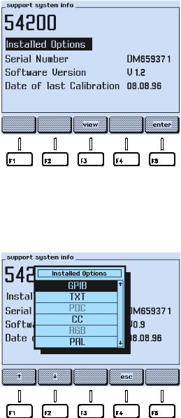
|
Installation and Safety Instructions |
1 |
GB |
Available built-in options Fluke 54200 |
Figure 1-5. Support System Info Submenu
•Press the view softkey (F3).
•A popup menu appears, showing the options.
Figure 1-6. Popup Menu showing installed Options
•Use the é or the ê softkey (F1 or F2) to scroll through the table.
Installed option are displayed in black letters, not installed options are display in grey letters.
1-7

54200
Users Manual
The meanings of the shortcuts are the following:
Table 1-1. Display Indication of built-in Options
54200 |
Description |
Options |
Display Indication |
|
Type numbers |
|
|
|
PAL |
PAL Standard |
54011 |
|
|
|
NTSC |
NTSC Standard |
54012 |
|
|
|
SECAM |
SECAM Standard |
54013 |
|
|
|
TXT |
Teletext and Widescreen |
54021 |
|
Signalling Bits |
|
|
|
|
PDC |
PDC / VPS (only in combination |
54022 |
|
with option 54021) |
|
|
|
|
CC |
Closed Caption |
54023 |
|
|
|
RGB |
RGB + YCrCb + YC |
54031 |
|
|
|
GPIB |
IEEE / RS-232 Interface |
54032 |
|
|
|
STEREO |
Mono Sound + Analog Stereo |
54061 |
|
|
|
NICAM |
Mono Sound + NICAM Sound |
54062 |
|
|
|
BTSC |
Mono Sound + BTSC Sound |
54063 |
|
|
|
•Press the esc softkey (F4) to return to the support system info submenu.
•Press the enter softkey (F5) to return to the support submenu.
•Press the enter softkey (F5) again to return to the main screen.
If you want additional options that are not built-in in your instrument at the moment, please contact you local Fluke Sales Organization.
1-8

|
Installation and Safety Instructions |
1 |
GB |
Introduction |
Introduction
This chapter should be read before unpacking, installing, and operating the instrument. It describes grounding, power cables, and fuses.
It also contains the Installation and Safety Instructions in the following languages: Spanish, Italian, Dutch and Swedish.
Safety Instructions
Upon delivery from the factory the instrument complies with the required safety regulations, see Chapter 7. To maintain this condition and to ensure safe operation, carefully follow the instructions below.
Maintenance and Repair
Failure and excessive stress:
If the instrument is suspected of being unsafe, remove it from operation immediately and secure it against any unintended operation. The instrument is considered to be unsafe when any of the following conditions exist:
•It shows physical damage.
•It does not function.
•It is stressed beyond the tolerable limits (e.g., during storage and transportation).
Disassembling the Instrument:
Warning
Calibration, maintenance, and repair of the instrument must be performed only by trained personnel who are aware of the hazards involved. To avoid electric shock, do not remove the cover unless you are qualified to do so.
Before removing the cover, disconnect the instrument from all power sources. The capacitors in the instrument may remain charged for several seconds after all power has been disconnected.
Grounding (Earthing)
Before any other connection is made, the instrument shall be connected to a protective earth conductor using the three-wire power cable.
The power plug shall be inserted only into a grounded outlet. Do not defeat the protective action by using of an extension cord without a grounded conductor.
Warning
Any interruption of the protective ground conductor inside or outside the instrument or disconnection of the protective ground terminal will make the instrument dangerous. Do not Intentionally interrupt the protective ground conductor.
The circuit ground potential is applied to the external contacts of the BNC connectors and is connected to the instrument case. The external contacts of the BNC connectors must not be used to connect a protective conductor.
1-9

54200
Users Manual
Power Cable, Line Voltage Range, and Fuses
Different power cables are available for the local line connectors. On delivery from the factory the instrument is supplied with the ordered power cable:
Table 1-2. Delivered Power Cable
Type No. |
Delivered |
|
Power Cable |
|
|
54200/XX1 |
Universal Europe |
54200/XX3 |
North America |
54200/XX4 |
England (UK) |
54200/XX5 |
Switzerland |
54200/XX8 |
Australia |
|
|
Before plugging in the power cable, make sure that the instrument is suitable for the correct line voltage.
Note
When the mains plug has to be adapted to the local situation, such adaptation should be done by a qualified technician only.
The instrument has a switched-mode mains power supply that covers most nominal voltage ranges in use: ac voltages from 100 to 240 V (r.m.s.). This obviates the need to adapt to the local line voltage. The nominal line frequency is 50 to 60 Hz.
Warning
The instrument shall be disconnected from all voltage sources when a fuse is to be renewed.
The fuses are located in a fuse holder of the input power module at the rear panel. When the line fuses need replacing, proceed as follows:
•disconnect the power cable from the power module.
•press the clip of the fuseholder and pull out the holder, see illustration.
•fit new fuses of the correct rating (according to IEC127 T1.6A or CSA/UL 198G T1.6A) and refit the fuseholder.
Warning
To avoid fire hazards, make sure the instrument fuses are of the type and current rating specified. Do not use repaired fuses and/or short-circuited fuseholders. Do not defeat this important safety feature.
1-10
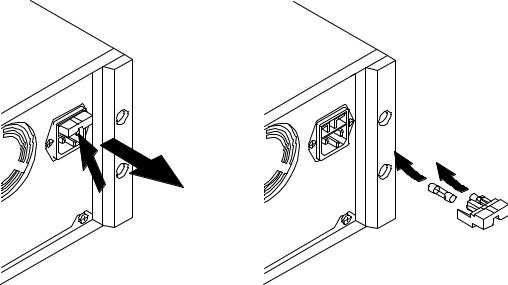
|
Installation and Safety Instructions |
1 |
GB |
Operating Position of the Instrument |
Operating Position of the Instrument
The instrument can be operated on a horizontal surface in a flat position or in a sloping position with the tilting feet folded down. Ensure that the ventilation holes are free of obstruction. Do not position the instrument in direct sunlight or on any surface that produces or radiates heat.
Radio Interference Suppression
Radio interference of the instrument is suppressed and checked carefully. If radio frequency interferences occur in connection with other poorly suppressed instruments, further suppression actions may be required.
Isolation Transformer
Because most MTV and CTV receivers are constructed with the chassis potentially 'live', it is sensible precaution to power the receiver under test using a suitable isolating transformer.
This permits direct connection of the television chassis to the earth terminals of any test instrument thus providing a common signal path and reducing the risk of electric shock.
1-11

54200
Users Manual
1-12
|
Installation and Safety Instructions |
1 |
E |
Instrucciones de instalación y de seguridad |
Instrucciones de instalación y de seguridad
Instrucciones de seguridad
El aparato sale de fábrica, técnicamente, en perfectas condiciones de seguridad (ver cap. 7). Para que se conserven estas condiciones, y para evitar riesgos en el uso, hay que seguir cuidadosamente las indicaciones siguientes.
Mantenimiento y reparación
Defectos y esfuerzos extraordinarios:
Si se piensa que el aparato ya no puede funcionar sin riesgo, hay que apagarlo y asegurarse de que no se ponga en funcionamiento inadvertidamente. Este es el caso:
•cuando el aparato presenta daños visibles,
•cuando el aparato no funciona,
•luego de haber sido sometido a esfuerzos excesivos de cualquier tipo (p.e.en el almacenaje o el transporte) que sobrepasan los límites permitidos.
Abrir el aparato:
 Advertencia
AI abrir algunas tapas o al desmontar piezas con herramientas pueden quedar al descubierto partes bajo tensión eléctrica. También puede haber tensión en los puntos de conexión. Antes de abrir el aparato hay que desconectarlo de todas las fuentes de alimentación.
Si es inevitable realizar un calibrado, mantenimiento o reparacién con el aparato abierto que se encuentra bajo tensión, sólo debe hacerio un técnico cualificado que conozca los riesgos que existen. Los condensadores del aparato pueden seguir estando cargados aùn cuando esté haya sido desconectado de todas las fuentes de alimentación.
Puesta a tierra
Antes de hacer alguna conexión hay que conectar el aparato a un contacter protección mediante el cable de alimentación de tres conductores.
El enchufe de la red debe ser insertado sólo en tomacorrientes con contacto de seguridad de tierra.
No se deben anular estas medidas de seguridad, p.e. usando un cable de extensión sin contactor de protección.
 Advertencia
Toda interrupción del contactor de protección dentro o fuera del aparato, o la separación de la conexión de la puesta protectora peligrosa. Se prohíbe hacer la interrupción expresamente.
1-13

54200
Users Manual
Los contactos exteriores de los casquillos BNC tienen el potencial del neutro y están conectados a la carcasa. La puesta a terra a través de los contactos exteriores de los casquillos BNC es inadecuada.
Cable de conducción eléctrica, rango de tensiones de la linea y fusibles
Existen diferentes cables de conducción eléctrica para los terminales de la conexión a la red. El instrumento se suministra desde fábrica con el cable de conducción eléctrica pedido.
Table 1-3. Cable suministrado
Tipo de aparato |
Cable |
|
suministrado |
|
|
54200/XX1 |
Europa |
54200/XX3 |
Norteamérica |
54200/XX4 |
Inglaterra (U.K.) |
54200/XX5 |
Suiza |
54200/XX8 |
Australia |
|
|
Antes de enchufar el cable de conducción eléctrica asegurarse que el instrumento esté ajustado a la tensión correcta de la red.
Nota
Para evitar daños o peligros de muerte, toda modificación en los cables de conducción eléctrica para adaptarlos a la corriente local deberá ejecutarse por personal cualificado que tiene conocimientos suficientes de los peligros existentes.
El instrumento tiene una conexión a la red conmutable que abarca los rangos de voltajes nominales más usuales: tensiones alternas desde desde 100 hasta 240 (valor efectivo). Con esto ya no es necesario adaptar la tensión de la red local. La frecuencia nominal de la red es de 50 a 60 Hz.
 Advertencia
Cuando se vaya a cambiar un fusible se ha de desconectar el instrumento de toda fuente de voltaje.
Los fusibles están colocados en el portafusibles del módulo de potencia de entrada del panel posterior. Para cambiar los fusibles del circuito proceder del siguiente modo:
•desconectar el cable de corriente del módulo de potencia,
•presionar la sujeción de apriete del portafusibles y sacar el portafusibles, ver la figura,
•colocar los nuevos fusibles con la potencia correcta (conforme a IEC127 T1,6A o CSA/UL 198G T1,6A) y montar otra vez el portafusibles.
1-14
 Loading...